Note: Descriptions are shown in the official language in which they were submitted.
1 2168612
This invention relates to a pressure measuring guide
wire comprising an elongated flexible shaft with a
proximal portion, a distal portion, a lumen extending
through the shaft, wall means surrounding said lumen,
and aperture means for entry of a pressure medium into
the lumen.
The value of intracoronary pressure recordings gives a
valuable information to the cardiologist to assess both
coronary and myocardial flow reserve and collateral
blood flow.
The problem of pressure measuring guide wires is to
provide an uninterrupted lumen throughout the shaft
which has to be highly flexible to conform with the
tortuous pathways of the blood vessels; simultaneously,
the shaft must have a reasonably high stiffness to
assure pushability and torque transmission thereto; and
furthermore, the shaft must have a very good kink
resistance to avoid the risk of constrictions resulting
in modification of the advance of pressure waves through
the lumen.
Current pressure measuring guide wires are made of a
plastic tube and a stiffening wire. This is, however,
very costly and leads to constrictions in the lumen
which obstruct the advance of pressure waves in the
lumen.
Another approach is shown in the document EP-A1-0419277
which describes a guide wire for use in measuring a
characteristic of liquid flow in a vessel comprising a
flexible elongate element in the form of a tube with a
core wire provided therein the distal extremity of which
is tapered and extends beyond the distal end of the
2168fi 11
tube. The tapered extremity of the core wire extends into a
coil spring which is soldered to the tube. The coil spring is
formed of two parts which are screwed together and the spring is
bonded to the core wire by solder at the region where the two
portions of the coil spring are screwed together. A safety wire
extends from the joint of the two coils to the distal extremity
of the coil spring where it is secured to a transducer carried
by the distal end of the coil spring. Front and rear contacts
are provided on the transducer and are connected to a two
conductor wire which extends rearwardly and interiorly of the
coil spring and further extends into the tube between the core
wire and the interior of the tube to get out of the tube for
connection to a male connector. According to a variant, an
insulating sleeve may form a tight fit with the exterior surface
of the core wire and it may also fit within the tube to insulate
the core from the tube so that the core and the tube and core
may serve as separate and independent electrical conductors.
It is desirable to improve over the cited art by means of a
pressure measuring guide wire which is easy and cheap to
manufacture, which is highly versatile while having excellent
qualities of pushability and resistance to kinking, and which
allows a smooth advance of pressure waves through the lumen.
The invention provides a pressure measuring guide wire
comprising an elongated flexible shaft with a proximal area, a
distal area, a lumen extending through the shaft, wall means
surrounding said lumen, and aperture means for entry of a
pressure medium into the lumen, wherein said wall means have a
first portion of length in the distal area of the shaft said
first portion of length having a first thickness and a plurality
of slots formed therein, and a second portion of length having a
A
216861
3
second thickness smaller than said first thickness, and wherein
coil means are supporting said second portion of length, whereby
said first portion of length has a first resistance to kinking
and said second portion of length has a second resistance to
kinking smaller than said first resistance to kinking.
The invention also provides a pressure measuring guide wire
comprising an elongated flexible shaft with a proximal area, a
distal area, a lumen, extending through the shaft, wall means
surrounding said lumen, and aperture means for entry of a
pressure medium into the lumen, wherein said wall means have a
first portion of length, a second portion of length in the
distal area of the shaft, said second portion of length having a
plurality of elongated slots formed therein, and wherein coil
means are located inside the shaft and extend at least under
said slots, whereby said first portion of length has a first
resistance to kinking and said second portion of length has a
second resistance to kinking smaller than said first resistance
to kinking.
Accordingly, it becomes possible to modulate the resistance to
kinking as a function of the structural organization for the
pressure medium entry into the lumen. The wall thickness may be
selected at will, whereby the shaft can be made flexible and
stiff enough to be pushed. The resistance to kinking can be
practically constant and the risk of constrictions due to
kinking is eliminated. A stiffening wire is no longer needed,
and there is a better frequency behaviour for the fluid medium.
The first portion of length is in the distal area of the shaft,
making it possible to select at will the configuration of the
supporting coil means.
3a 2 1 6 8
The second portion of length has a second thickness smaller than
that of the first portion of length having a plurality of slots
formed therein for entry of the pressure medium, the mere choice
of thickness allows mastering the difference in resistance to
kinking due to the presence of the slots.
Within this frame, the first portion of length has a first outer
diameter and the second portion of length has a second outer
diameter smaller than the first outer diameter, whereby the coil
means may surround the second portion of length. In this
configuration, the coil means and diameters may be easily chosen
to have the coil means in flush alignment with the first outer
diameter, for having an overall outer diameter constant and
reduced friction upon travelling through the blood
21686 12
vessels. And to assure simple positioning of the coil
means on the second portion of length, this second
portion of length may be preceded proximally by a third
portion of length having a third outer diameter larger
than said second outer diameter, with the coil means
surrounding the second portion of length between said
first and third outer diameters. In that configuration
the coil means may also be in flush alignment with the
first outer diameter for the same reason of diameter
constancy and friction reduction.
Still within this frame, the first portion of length may
have a first inner diameter and the second portion of
length may have a second inner diameter larger than the
first inner diameter, whereby the coil means may be
located within the second portion of length. In this
configuration, the coil means and diameters may also be
easily chosen to have the coil means in flush alignment
with the first inner diameter for having an overall
outer shaft surface which is homogeneous while the inner
diameter of the shaft remains constant.
In any of the arrangements with the first portion of
length in the distal area of the shaft and with slots
formed in the first portion of length, some of the slots
may be proximal of the first portion of length with some
other slots being distal of the first portion of length,
thereby avoiding too many holes on the same diameter in
order to minimize the risk of kinking resistance
reduction in that area.
Where the second portion of length has a plurality of
elongated slots formed therein for entry of the pressure
medium and the coil means are located inside the shaft
and extend at least under the slots, a very small
thickness of the wall may be achieved all along the
2168612
shaft, including the weakened area of slot location
which is supported by the coil means which avoids the
risk of kinking in that delicate area. And as the slots
are fully supported by the coil means, they can be
located at the same level along the second portion of
length. To facilitate entry of the pressure medium, the
coil means may have adjacent windings which are spaced
apart from one another extending at least under the
slots.
In order to stiffen the coil means without interfering
with the shaft, core means may extend through the coil
means. Where such core means have a proximal portion for
longitudinal abutment against a proximal end of the coil
means and a distal portion for longitudinal abutment
with a distal end of the coil means, a stress free
assembly is achieved which stiffens the turns of the
coil means and which leaves the shaft lumen free of any
obstruction proximally of the coil means. The core means
may also have their proximal portion integral with a
wire which extends proximally along and out of the lumen
of the shaft. In that case, the supporting coil may be
placed under the slots only for insertion of the guide
wire to assure the required resistance to kinking.
During insertion, the wire extending the core also has
some stiffening effect for the shaft and improves its
pushability. When the guide wire is properly located,
the wire and supporting coil are removed from the guide
wire to have the shaft lumen fully free of obstruction
for pressure measurements.
These and other objects, features and advantages of the
invention will become readily apparent from the
following detailed description with reference to the
accompanying drawings which show, diagrammatically and
2168612
by way of example only, t~~e~ e~nbodi~ne~ts o~ the
invention.
Figure 1 is a cross sectional view of the first
embodiment.
Figure 2 is a cross sectional view of the second
embodiment.
Figure 3 is a cross sectional view of the third
embodiment.
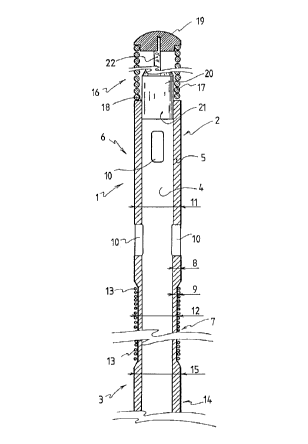
The guide wire shown in Figure 1 comprises an elongated
flexible shaft 1 having a distal area 2 and a proximal
area 3. A lumen 4 extends through the shaft 1, and the
proximal area 3 of the shaft is intended to be connected
to a pressure measuring and monitoring equipment (not
shown) common in the art.
Preferably, the shaft 1 is made of an elastic Nickel
Titanium alloy such as for instance Nitinol (Trade Name)
or Tinel Alloy (Trade Name). Other materials are also
possible, for instance plastic materials.
The lumen 4 is surrounded by a wall 5 forming the shaft
1 and having a first portion of length 6 and a second
portion of length 7. The first portion of length 6 is
located in the distal area 2 of the shaft 1 and it has a
first thickness 8; the second portion of length 7 is
located in the proximal area 3 of shaft 1 and it has a
second thickness 9, smaller than the first thickness 8,
thereby achieving a resistance to kinking which is
smaller than that of the first portion of length 6. The
difference in thickness results from the fact that the
first portion of length 6 has an outer diameter 11
7 2168612
longer than the diameter 12 of the second portion of
length 7.
The first portion of length 6 has a plurality of slots
-10 -formed therE-in f.o-r entry .of the pressure medium; some
of these slots 10 are proximal of the first portion of
length 6 and some other of these slats are distal of the
first portion of length 6.
A coil 13, preferably of a high density metal such as
for instanEe Tungsten, is mounted on the second portion
of length 7 for supporting purposes. This h~.gh density
metal coil also provides a radiopaque reference for the
first portion of length 6. This coil 13 is in flush
alignment with the outer diameter 11 of the first
portion of length 6.
The second portion of length 7 is preceded proximally by
a third portion of length 14 of wall 5 having an outer
diameter 15 greater than the second diameter 12, in the
example shown, equal to the first outer diameter 11. The
coil 13 is thus comprised between the first diameter 11
and the third diameter 15.
The distal area 2 of shaft 1 terminates in a flexible
assembly 16 comprising a coil 17, preferably made of a
high density metal such as Tungsten, which also provides
a radiopaque reference for the first portion of length 6
which is thus easily locatable between the two
radiopaque references provided for by coils 13 and 17.
The coil 17 abuts proximally on the distal end 18 of
shaft 1 and its distal extremity terminates into a tip
19. A cylindrical core 20, for example of stainless
steel, has its proximal portion 21 affixed, for instance
welded, into the distal end 18 of shaft 1; core 19
2168612
tapers into a flattened straight and narrow distal
portion 22 which terminates by welding into the tip 19.
The guide wire shown in Figure 2 also comprises an
elongated flexible shaft 31 having a distal area 32 and
a proximal area 33. A lumen 34 extends through the shaft
31, and as for the embodiment of Figure 1 the proximal
area 33 of the shaft 31 is intended to be connected to a
pressure and monitoring equipment (not shown).
Preferably, the shaft 31 is also made of an elastic
Nickel Titanium alloy such as Nitinol (Trade Name) or
Tinel Alloy (Trade Name), but other materials such as
plastic materials are also possible.
The lumen 34 is surrounded by a wall 35 forming the
shaft 31 and having a first portion of length 36 and a
second portion of length 37. The first portion of length
36 is located in the proximal area 33 of shaft 31; the
second portion of length 37 is located in the distal
area 32 of shaft 31 and it has a plurality of elongated
slots 38 formed therein for pressure medium entry,
thereby achieving a resistance to kinking which is
smaller than that of the first portion of length 36
which is devoid of slots. The slots 38 may be located at
the same level along the second portion of length 37, as
shown.
A coil 39, preferably of a high density metal such as
for example Tungsten, is located inside the shaft 31
under the slots 38 for supporting the wall and slot
structure and for providing a radiopaque reference for
the second portion of length 37. This coil 39 extends
somewhat beyond the slots 38 and, as shown, it may have
adjacent windings which are spaced apart from one
2168612
another to facilitate entry of the pressure medium
within the lumen 34.
A core member 41, preferably in stainless steel, is
located within the coil 39. This core member 41 has a
proximal portion 42 in the form of a truncated cone for
longitudinal engagement with the proximal end of the
coil 39, and a distal portion 43 which is flattened so
that the resulting enlargement abuts longitudinally
against the distal end of the coil 39.
The distal area 32 of shaft 31 terminates in a flexible
assembly 44, as described in European Patent Application
N° 95103006.3 filed March 2, 1995 comprising a first
coil 45 having a proximal portion 46 and a distal
portion 47, and a second coil 48 having a proximal
portion 49 and a distal portion 50 ending in a weld tip
51. The proximal portion 46 of first coil 45 comprises
adjacent windings which are spaced apart and this
proximal portion 46 is threadedly force fitted into the
tubular distal area 32 of shaft 31. An adhesive may be
injected between the windings of proximal portion 46 of
coil 45. This first coil is made of a high density
metal, preferably Tungsten, to provide a radiopaque
reference for the flexible assembly 44. The second coil
48, also made of a high density metal such as Tungsten,
has its proximal portion 49 threadingly surrounding the
distal portion of first coil 45 and abutting against the
distal end of shaft 31. A cylindrical core 52,
preferably of stainless steel, extends through the coil
45 and has a proximal portion 53 flattened so that the
resulting enlargement abuts longitudinally against the
proximal end 46 of coil 45. The core 52 tapers into a
flattened straight and narrow portion 54 which
terminates by welding into the tip 51.
21686 12
to
The guide wire shown in Figure 3 comprises the same
integers and corresponding reference numerals as the
guide wire of Figure 2. Additionnally, core 41 has its
truncated cone proximal portion 42 integral with the
distal end of a wire 60 which extends along lumen 34 up
to the proximal end of shaft 31 where it can be grasped
for taking the assembly of core 41 and coil 39 out of
the shaft 31. Accordingly, the coil 39 may be placed and
maintained under the slots 38 only for insertion of the
guide wire and withdrawn from the guide wire for
pressure measuring.
Variants are available without departing from the scope
of the invention.
For instance, the flexible assembly 16 of the first
embodiment of Figure 1 may be replaced by the flexible
assembly 44 of the embodiment of Figure 2 and vice
versa.
The second portion of length 7 of the embodiment of
Figure 1 may have an inner diameter which is larger than
the inner diameter of the first portion of length 6,
whereby the coil 13 may be located inside the second
portion of length 7, preferably in flush alignment with
the inner diameter of the first portion of length.