Language selection

Search

Patent 2168742 Summary

Third-party information liability

Some of the information on this Web page has been provided by external sources. The Government of Canada is not responsible for the accuracy, reliability or currency of the information supplied by external sources. Users wishing to rely upon this information should consult directly with the source of the information. Content provided by external sources is not subject to official languages, privacy and accessibility requirements.

Claims and Abstract availability

Any discrepancies in the text and image of the Claims and Abstract are due to differing posting times. Text of the Claims and Abstract are posted:

  • At the time the application is open to public inspection;
  • At the time of issue of the patent (grant).
(12) Patent Application: (11) CA 2168742
(54) English Title: LEG EXERCISE DEVICE
(54) French Title: DISPOSITIF D'EXERCICE PERMETTANT DE FAIRE TRAVAILLER UNE JAMBE
Status: Dead
Bibliographic Data
(51) International Patent Classification (IPC):
  • A63B 22/08 (2006.01)
  • A61F 5/04 (2006.01)
  • A61H 1/02 (2006.01)
  • A63B 23/04 (2006.01)
(72) Inventors :
  • WOHLENBERG, ROBERT MARTIN (Australia)
(73) Owners :
  • ORTHOPAEDIC REHABILITATION PRODUCTS PTY. LTD. (Australia)
(71) Applicants :
(74) Agent: FETHERSTONHAUGH & CO.
(74) Associate agent:
(45) Issued:
(86) PCT Filing Date: 1995-06-02
(87) Open to Public Inspection: 1995-12-14
Examination requested: 2002-02-11
Availability of licence: N/A
(25) Language of filing: English

Patent Cooperation Treaty (PCT): Yes
(86) PCT Filing Number: PCT/AU1995/000328
(87) International Publication Number: WO1995/033526
(85) National Entry: 1996-02-02

(30) Application Priority Data:
Application No. Country/Territory Date
PM 6063 Australia 1994-06-03

Abstracts

English Abstract


A damaged knee joint receives phys-
iotherapy treatment by engaging the heel of
a patient in a cradle (12, 24) at the lower
end of a lever (11, 22), engaging a fulcrum
member (17, 26) either just above or just
below the knee joint, and pulling a handle
(20, 23) of lever (11, 22) to articulate the
knee joint.


French Abstract

L'invention concerne un dispositif de physiothérapie pour soigner une articulation de genou endommagée. Le patient met son talon dans un étrier (12, 14) à l'extrémité inférieure d'un levier (11, 12), prend appui sur un élément d'appui (17, 26) venant se placer juste au-dessus ou en dessous du genou, et tire sur la poignée (20, 23) du levier (11, 12) pour faire bouger l'articulation du genou.

Claims

Note: Claims are shown in the official language in which they were submitted.


- 5 -

THE CLAIMS DEFINING THE INVENTION ARE AS FOLLOWS:
1. A leg exercising device for exercising the knee joint of a
patient's leg, comprising an elongate lever having a cradle at one end of shape
to cradle a lower portion of a patient's leg,
a fulcrum member carried on said lever intermediate its ends and
shaped to bear against a patient's said leg near its knee joint when said one
end cradles said lower leg portion,
the other of said ends comprising a handle useable by a patient to effect
articulation of said knee joint.
2. A leg exercising device according to claim 1 further
comprising distance adjustment means between said fulcrum member and said
cradle.
3. A leg exercising device according to claim 2 wherein said
fulcrum member comprises a saddle slidable over said lever, said lever having
a plurality of spaced apertures extending part way along it, and said adjustmentmeans comprising an insertion pin on said saddle which is selectively
insertable into any one of said apertures.
4. A leg exercising device according to claim 1 further
comprising a saddle slidable along said lever, releasable adjustment means
between said saddle and said lever operable to retain said saddle to said lever
adjustably for position, and a pressure pad, and wherein said fulcrum member
comprises a pivot pin connecting said pressure pad and said saddle.
5. A leg exercising device according to claim 4 wherein said
saddle comprises a strut between said adjustment means and pivot pin.
6. A leg exercising device according to claim 2 wherein said
distance adjustment means comprises telescopic lever portions of square tube
between said fulcrum member and said cradle.


- 6 -

7. A leg exercising device according to claim 1 wherein said
lever comprises an upper portion and a lower portion each of square section
tube, said handle being on the upper end of the upper portion, a said cradle
being on the lower end of the lower portion,
adjacent ends of said lever portions extending laterally and engaging
each other telescopically.
8. A leg exercising device according to claim 7 wherein said
lower portion of said lever itself comprises telescopically engaging surfaces
which provide adjustment of distance between said cradle and said laterally
extending lever portion adjacent ends.
9. A leg exercising device according to claim 7 wherein said
fulcrum member comprises a contoured pad carried on said laterally extending
lever portion adjacent ends.
10. A method of exercising the knee joint of a human leg,
comprising cradling the heel of a patient in said cradle of claim 1, locating said
fulcrum member adjacent said knee joint, and moving said lever arm by said
handle to articulate said knee joint.
11. A leg exercising device substantially as hereinbefore
described with reference to and as illustrated in Figs 1 to 5.
12. A leg exercising device substantially as hereinbefore
described with reference to and as illustrated in Fig 6.

Description

Note: Descriptions are shown in the official language in which they were submitted.


WO 95/33526 Z ~ 6 8 ~ ~ ~ PCT/AU95/00328
.


- 1 -
LEG EXERCISE DEVICE
This invention relates to a device for the exercising of a leg, and
although not necessarily limited to assisting a patient to straighten a leg in
post-operative physio therapy, the invention is specifically useful in such a
5 situation. The invention further extends to a method of exercising a leg which tends to remain bent at the knee.
The knee is the joint which is frequently damaged in injuries for example
sport injuries, and quite often needs major surgery. Frequently, after the
surgery has been completed the knee has moved to a bent position instead of
10 the stretched out position and it is necessary to subject a patient to
considerable physiotherapy before full use is resumed. In order to achieve
straightening of the leg at the knee, it is common practice to subject the knee to
a considerable weight or force which tends to slowly straighten the leg, but this
is painful and has been found to be less effective than being able to "work" the15 knee joint and thereby achieve the required physical changes to make the knee once again useful.
BACKGROUND OF THE INVENTION
In an embodiment of the invention there is provided means which
support the ankle or heel of a patient and apply pressure downwardly near the
20 knee joint intermittently, and enable the knee joint to "work", that is, to articulate
so as to reduce resistance to use.
A particularly useful embodiment of the invention utilises an elongate
lever having a cradle at one end which can cradle the heel or behind the ankle
of a patient's leg, and intermediate the ends a fulcrum member is carried
25 adjustably for position on the lever and shaped to bear against the patient's leg
near the locality of the knee while the other end of the lever is provided with a


WO 95/33526 ~ 6<~ 2 - PCTlAU9~i/00328
handle so that a user can use his hand and arm to effect articulation of the
knee joint.
PRIOR ART
No prior art is known to the Applicant wherein use is made of an
5 elongate bar having a cradle at one end to accept the heel of a patient, a
handle at the other end, and a fulcrum between the ends which can engage a
patient's leg near the knee joint. The closest art appears to be in US patents
4,463,947 Kloenne, and 4,844,454 Rogers.
Specifically, the invention consists of an elongate lever having a cradle
10 at one end of shape to cradle a lower portion (the heel or ankle) of a patent's
leg, a fulcrum member carried on said lever intermediate its ends and shaped
to bear against a patient's said leg near its knee joint when said one end
cradles said lower leg portion, the other of said ends comprising a handle
useable by a patient to effect articulation of said knee joint.
BRIEF SUMMARY OF THE DRAWINGS
Two embodiments of the invention are described hereunder in some
detail with reference to, and are illustrated in, the accompanying drawings, in
which
Fig 1 is a perspective view of a leg exercising device, according to a first
embodiment;
Fig 2 is a cross-section on plane 2-2-2-2 of Fig 1;
Fig 3 is a fragmentary longitudinal section on plane 3-3 of Fig 2;
Fig 4 shows use of the first embodiment device with the fulcrum below
the knee;
Fig 5 is a view similar to Fig 2, but with the fulcrum above the knee; and
Fig 6 depicts an alternative arrangement wherein components can be
"knocked down" to occupy less packaging space than the first embodiment.

WO 95/33526 '2 1 ~6 8 74 ~ PCT/AU95/00328
.


- 3 -
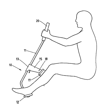
Referring firstly to the embodiment of Figs 1 to 5, a leg exercise device
10 comprises an elongate lever 11 which has a depending hook like cradle 12
at the lower end arranged to engage either the heel or behind the ankle of a
-t patient's leg, while intermediate the ends of the lever 11 is provided with a
saddle 13 which is slidable along the lever 11 but can be located in alternativepositions by means of an insertion pin 14 which is selectively inserted in any
one of a plurality of apertures which extend through a wall of lever 11 for part of
its length. A strut 15 extends from the saddle 13 and is joined at its other endto a shallow U shaped bracket 16 which carries a pressure plate 17, by pivot
pin 18, such that plate 17 and pin 18 combine to form a fulcrum. The end of
the lever 11 which is spaced furthest from the cradle 12, terminates in a handle20 which can be actuated by a patient, and if the patient moves the handle 20
he can cause the knee to articulate, and if he does so intermittently he can
control the frequency and amplitude of movement which is developed. It has
been found surprisingly that it is better to apply the load intermittently within a
range of pain tolerance, particularly if done by hand, and the resultant
correction of the knee joint is more effective and more quickly and easily
achieved than heretofore. Figs 4 and 5 respectively show the pressure plate
17 bearing against the leg below and above the patient's knee.
Fig 6 shows an alternative arrangement, wherein the leg exercise device
21 has a "broken~ lever comprising an upper portion 22a and a lower portion
22b, handle 23 being on an end of portion 22a, and cradle 24 on an end of the
lower portion 22b.
The two portions 22a and 22b both comprise square tubing, and are
joined intermediate their ends by a telescopic joint at 25 in laterally extending
adjacent ends of the handle portions. The laterally extending adjacent ends at

WO 95/33526 PCT/AU95/00328
~6~7~ ~

25 carry a contoured resilient pad 26, retained in position by the extending
portions 22a and 22b of the lever.
As shown, portion 22b is telescopic also at its lower end, so that cradle
24 can also be removed for packaging, or positioned for the most effective use
5 of the device.
The second embodiment has certain advantages over the first. There is
no latch arrangement, such as insertion pin 14, friction between the telescopic
sliding surfaces being sufficient to retain the lower portions in their adjustedpositions. The cost of the pad 26 (which functions as the fulcrum member) is
10 much less than the cost of the fulcrum member of the first embodiment.
A consideration of the above embodiments will indicate that the
invention is very simple, but experiments have indicated that it is likely to bevery much more effective than the "dead weight" system which has been used
in prior art.

Representative Drawing
A single figure which represents the drawing illustrating the invention.
Administrative Status

For a clearer understanding of the status of the application/patent presented on this page, the site Disclaimer , as well as the definitions for Patent , Administrative Status , Maintenance Fee  and Payment History  should be consulted.

Administrative Status

Title Date
Forecasted Issue Date Unavailable
(86) PCT Filing Date 1995-06-02
(87) PCT Publication Date 1995-12-14
(85) National Entry 1996-02-02
Examination Requested 2002-02-11
Dead Application 2003-06-02

Abandonment History

Abandonment Date Reason Reinstatement Date
2002-06-03 FAILURE TO PAY APPLICATION MAINTENANCE FEE

Payment History

Fee Type Anniversary Year Due Date Amount Paid Paid Date
Application Fee $0.00 1996-02-02
Registration of a document - section 124 $0.00 1996-10-17
Maintenance Fee - Application - New Act 2 1997-06-02 $50.00 1997-05-21
Maintenance Fee - Application - New Act 3 1998-06-02 $50.00 1998-05-07
Maintenance Fee - Application - New Act 4 1999-06-02 $50.00 1999-05-26
Maintenance Fee - Application - New Act 5 2000-06-02 $75.00 2000-05-12
Maintenance Fee - Application - New Act 6 2001-06-04 $75.00 2001-05-03
Request for Examination $400.00 2002-02-11
Owners on Record

Note: Records showing the ownership history in alphabetical order.

Current Owners on Record
ORTHOPAEDIC REHABILITATION PRODUCTS PTY. LTD.
Past Owners on Record
WOHLENBERG, ROBERT MARTIN
Past Owners that do not appear in the "Owners on Record" listing will appear in other documentation within the application.
Documents

To view selected files, please enter reCAPTCHA code :


To view images, click a link in the Document Description column. To download the documents, select one or more checkboxes in the first column and then click the "Download Selected in PDF format (Zip Archive)" or the "Download Selected as Single PDF" button.

List of published and non-published patent-specific documents on the CPD .

If you have any difficulty accessing content, you can call the Client Service Centre at 1-866-997-1936 or send them an e-mail at CIPO Client Service Centre.


Document
Description 
Date
(yyyy-mm-dd) 
Number of pages   Size of Image (KB) 
Claims 1995-06-02 2 76
Description 1995-06-02 4 156
Drawings 1995-06-02 4 54
Representative Drawing 1997-06-12 1 6
Cover Page 1995-06-02 1 17
Abstract 1995-06-02 1 44
Fees 1998-05-07 1 48
Correspondence 2000-05-12 1 31
Correspondence 2001-05-03 1 33
Prosecution-Amendment 2002-02-26 1 32
Assignment 1996-02-02 10 379
PCT 1996-02-02 2 92
Prosecution-Amendment 2002-02-11 1 34
Correspondence 1996-05-14 7 234
Fees 1997-05-21 1 47