Note: Descriptions are shown in the official language in which they were submitted.
LAN1~1TBD SHBBT' AND MANUFACTORING METHOD T~OF
Technological f field
This invention concerns laminated sheet and a
manufacturing method for it. This invention especially
concerns the laminated sheet for beverage or food cans and the
efficient manufacturing method of it, and it consists of
a thermoplastic the resin film and metallic substrate.
Background technoloc;v
A two piece can which consists of the can body
combined with the bottom lid is used for the food can or the
beverage can. Those cans are formed .from a metal substrate
such as a cold rolled steel sheet, an aluminum sheet or
i
tinplate. Those cans are usually coated by various resin
coating in order to prevent the metal from being dissolved into
the contents and to improve its corrosion resistance and
durability .
The above-mentioned two-piece can is occasionally
foamed by means of drawing the laminated sheet which is
produced by laminating the resin film to the metal substrate.
Such laminated sheet should endure the drawing, the ironing or
the stretching processing.
Therefore, the laminated sheet is produced by a
method of laminating the resin film without using adhesive
(Japanese patent Application No. TOKU-KOU-SHO 60-47103) or by
a method Df laminating a polyester film which is coated with
epoxy resin together with curing agent, etc. ( e.g. Japanese
~~~8°~6~
Application N0. TOKU-KOU-SHO 63-13829 or No.
TORU-KAI-HEI 1-249331).
One of the required can performances is~ denting
resistance in the drawn and formed can. There must be impact
resistance of the film when the dent is caused and also
resistance to cracking of the film.
The present Applicant has proposed to use the steel
sheet covered with bi-axially oriented or un-oriented polyester
resin film which has a specified intrinsic viscosity as a
material of the laminated can (Japanese Patent Application No.
TOKU-KAI-HEI 4-224936).
Above-mentioned bi-axially oriented polyester resin
film improves the strength and the denting resistance because
the crystalline structure is highly oriented (the molecule is
highly oriented). However, Such a-polyester film doesn't have
enough adhesion to the metal substrate. Therefore it peels off
easily during drawing process or ironing process.
In order to solve such problems, the resin film is
laminated to the metal substrate which is heated in advance.
As a result, the crystal orientation of the film on the side of
metal substrate decreases to some degree. And, adhesion and
bonding improve.
So this is a method of giving the inclination in the
direction of thickness of the film concerning crystal
orientation. However, the denting resistance of the can
decreases when crystal orientation of the.film decreases too
much and it causes a problem concerning the durability of the
2 -
CA 02168763 1999-11-03
can.
In order to improve adhesion, it has been proposed
that the film of laminated sheet be partially heated
especially for the high adhesion required part just
before the drawing process (Japanese patent application
No. TOKU-KAI-HEI 4-118121). However, it is difficult to
control and maintain the film temperature within the
range from the glass transition temperature to the
temperature of the re-crystallization.
This invention relates to the laminated sheet for
the can which laminated sheet has excellent denting
resistance and adhesion, and the method of manufacturing
it.
That laminated sheet improves the denting resistance
of the part where considerable denting is likely to occur
such as can bottom etc., and also improves the adhesion
of the film to the metal substrate in the other parts.
More specifically, the present invention relates to
a laminated sheet consisting of a metal substrate and an
oriented thermoplastic resin film laminated on the metal
substrate, wherein the degree of crystal orientation of
the resin film is varied in the planar direction in order
that the highly crystal line oriented part of the resin
film is set to the lightly processed part of the
laminated sheet and the lightly crystal line oriented
part of the resin film is set to the heavily processed
part of the laminated sheet.
The invention also relates to a method consisting of
heating the metal substrate, putting a highly crystal
line oriented resin film on the metal substrate, and
pressing the resin film and the metal substrate to
adhesion by a laminating roll, wherein means having
prescribed cooling pattern which set only to the lightly
processed part of the laminated sheet is provided, and
the metal substrate or laminated sheet is cooled by the
prescribed cooling pattern.
- 3 -
CA 02168763 1999-11-03
Furthermore, that laminated sheet can be simply
formed into cans and the damage at the time of
circulation is small and durability is high.
Brief explanation of drawings
Figure 1 is projected drawing which shows one
example of the laminated sheet of the present invention.
Figure 2(a) is a magnified cross section of the
laminated sheet and Figure 2(b) is an expanded cross
section which shows other example of the laminated sheet
of the present invention.
- 3a -
i
,1
!y
Figure 3 is an explanation drawing which shows the
transition of X-ray diffractive intention which corresponds to
the degree of crystal orientation of the laminated film.
Figure 4(a) - (d) are projected drawings which show
the example of the blank present invention, respectively.
Figure 5(a) - (c) pattern of the are the process
charts of the method of producing the drawing can from the
laminated sheet shown in Figure 1.
Figure 6(a) is the lengthwise cross section which
shows laminated can produced by the method shown in Figure 5
and Figure 6(b) is the lengthwise cross section of the
additionally formed laminated can.
Figure 7 is a process chart which shows an example of
the manufacturing method of the laminated sheet of the present
invention.
Figure 8 is a front view which shows an example of
the heating roll used for the manufacturing the laminated sheet
of the present invention.
Figure 9 is a cross section which shows an example of
the cooling roll used for the manufacturing method of the
laminated sheet of the present invention.
Figure 10 is a cross section which shows an example
of the ruminating roll used for the manufacturing of the
laminated sheet of the present invention.
Figure 11 is a perspective drawing of the cooling
roll shown in Figure 9.
Figure 12 is a A-A line cross section of Figure 11.
- 4 -
- ~~~~~~~ i
Figure 13 is a process chart which shows another
examples of the manufacturing method of the laminated sheet of
the present invention.
Figure 14 is a process chart which shows the other
example of the manufacturing method of the laminated sheet of
the present invention.
Figure 15 is a magnified cross section of the resin
film and the metal substrate laminated by the method shown in
i
Figure 14.
The best a~amner to practice the present imrention.
Next, the laminated sheet of the present invention
and the example of the manufacturing method are explained
referring to each Figure.
The laminated sheet 1 shown in figure 1 consists of
the metal substrate 2 and the resin film 3 laminated on one of
the surfaces of it as shown in Figure 2(a).
The laminated sheet 1 is provided in the form of a
coiled strip having a constant width,W.
In some cases, there can be the adhesive between the
metal substrate 2 and the resin film 3.
In addition, resin film 3 can be laminated to both
sides of the metal substrate as shown in figure 2(b).
The above mentioned laminated sheet 1 having constant
width W is punched out into disk blank 4 to form the cup and
the three disk blanks in each-line are zigzagingly punched out
with constant difference.
The imaginary outline of the blank pattern is shown
_ 5 _
I
r
i~
- ~18~~ ;,
on the laminated sheet 1.
In the center part 5 of each blank 4 (shown by
hatching), which corresponds to the bottom when the blank is
formed into a cup, the crystal orientation of the resin film is
high. However, it is low in other parts .
The shape of blank 4 can be designed in any shape
according to the final product to be formed.
For instance, as shown in Figure 4 (a) - (d) , the shape
of high crystal orientated part corresponding to the bottom of
the final cup, which is circle 5 (a) , oval 5 (b) square 5 (c) or
rectangle 5(d) is designed in the blank for a cylindrical cup,
oval cup, square cup or rectangular cup. In the present
invention, any other shapes are available.
The thickness of the metal substrate 2 can be changed
according to the kind of metal, and to the usage of the
container or the container size. Generally, a metallic sheet
is desirable from 0.10 to 0.50 mm in thickness and is excellent
especially from 0.15 to 0.40 mm in thickness.
Various surface treated steel sheet and aluminum,
etc. are used as a metal substrate.
First of all, surface treated steel sheet .is
explained. The surface treated steel sheet is made of cold-
rolled steel sheet, which is annealed and secondly cold-rolled.
The cold-rolled steel sheet is surface treated by one of the
following treatment groups consisting of electrolytical
chromium coating and the chromate treatment, etc.
The cold-rolled sheet is treated with one or more
- 6 -
kinds of these surface treatments. One of the suitable surface
i
treated steel sheet types is electrolytically chromium coated
i
steel sheet (TFS). Especiallypreferable is one having a double
layer consisting of a lower,metallic chromium layer having 10
to 200 mg/mz of metallic chromium and an upper hydrated
chromium oxide layer having 1 to 50 mg/mz of chromium .
In case where polyester film is laminated to it, it
is preferable that the hydrated chromium oxide layer has 3 -50
mg/m2, especially 7 - 25 mg/m2 of metallic chromium. The
laminated polyester film on the electrolytically chromium
coated steel sheet is excellent in adhesion and corrosion-
resistance.
One of the other surface treated steel sheet types is
tinplate coated with 0.5 - 11.2 g/m2 of tin. This tinplate
should be coated with 1 to 30 mg/m2 hydrated chromium oxide
formed by chromate treatment or chromate -phosphate treatment.
In addition, one of the other examples is aluminum
coated steel sheet which gives aluminum plated or aluminum
laminated steel sheet.
Besides pure aluminum, an aluminum alloy sheet
can be used as the light metal sheet. An aluminum alloy
excellent in corrosion-resistance and formability is one
having 0.2 -1.5 wt % of Mn, 0.8 - 5 wt % of Mg, 1.25 - 0.3 wt %
I
of Zn and 0.15 - 0.25 wt % of Cu.
These light metal substrates can be treated by the
organic or inorganic treatment.
The above-mentioned resin film 3 is made from a
molecular oriented thermoplastic resin and a higher crystal
orientated one is more preferable.
The resin film should be oriented in only the
lengthwise direction (uniaxial) or in~the lengthwise and width
direction (bi-axial), unlike film which is formed only by
drawing after being formed into extruded film.
The above-mentioned degree of crystal orientation can
be measured from the intention of the peak of an X-ray
diffraction pattern. Moreover, it is possible to be measured
optically by an Abbe refractometer.
The method by which the degree of the crystal
orientations is calculated from the peak height of X-ray
diffraction pattern is shown as follows. Concretely, (100)
plane parallel to the film surface is scanned by means of X
rays and the diffracted intensity is measured. And the crystal
orientation is calculated as the ratio of the diffracted
intensity of X-ray to that of before lamination.
The laminated film of the present invention should
have more than 90% of Crystal orientation at the place
corresponding to the bottom of the can and have about 5°s of
crystal orientation at the other parts. ,
Figure 3 shows the transition of the degree of
crystal orientation.
When X-gays are continuously scanned to part 5 (where
crystal orientation is high) which corresponds to the bottom
along arrow A, the diffraction intensity of X-ray is obtained
as shown in figure 3.
_ g _
i
That is, the degree of the crystal orientation of the
film becomes about 95% in part 5 which corresponds to the
bottom, and it is about 5% in the other parts.
Wherever the film thickness of the formed can is in i
the range of 5 to 20 Vim, the resin film having crystal
orientation previously mentioned can have excellent heat
resistance, strength and permeation resistance. Therefore, the
resin film should be one which can be crystal oriented '
(molecularly oriented) and be suitably oriented by heating,
drawing, redrawing and ironing.
The following resins can be used as the film material
of the present invention, for example, an olefin resin such as
polyethylene, polypropylene, and ethylene propylene copolymer,
ethylene acrylic ester copolymer and ionomer.
Also available are polyester .resins such as
polyethylene terephthalate, polybutylene terephthalate,
ethylene terephthalate/isophthalate copolyester, ethylene
terephthalate/adipate copolyester, ethylene
terephthalate/sebacate copolyester and butylene terephthalate/
isophthalate copolyester; polyamide resins such as nylon 6,
nylon 66, nylon 11 and nylon 12; polyvinyl chloride;
polyvinylidene chloride; polycarbonate resins such as poly-p-
xyleneglycol biscarbonete, poly-dioxydiphenyl ethane carbonate,
poly-dioxdiphenyl 2,2-propane carbonate, poly dioxydiphenyl
1,1-ethane carbonate, high nitrile resins such as
acrylonitrile-butadiene copolymer with the high content of
nitrile, acrylonitrile-styrene copolymer, polystyrene copolymer
9
.I
i
etc., which satisfy preceding conditions.
In the present invention, all the above-mentioned
resins can be used.
An especially suitable resin film is one consisting
of polyester, which mainly comprises the recurring unit of
ethylene terephthalate, and is bi-axially oriented.
Polyester resin should be the one in which 75-95%
recurring consists of ethylene terephtalate units and 5-25%
remainder consists of units of another ester.
Other acid components than terephthalic acid which
can be used are phthalic acid, isophthalic acid, succinic acid,
azelaic acid, adipic acid, sebacic acid, dodecanic acid,
Biphenyl carboxylic acid, 1,4 cyclophexane dicarboxylic acid,
trimellitic anhydride acid and one or more kinds of these acids
Other alcohol components which can be used are
saturated polyhydric alcohol such as '1,4 butanediol, 1,5
pentanediol, 1,6 hexanediol, propyleneglycol,
polytetramethyceneglycol, trimethylene glycol, triethylene
glycol, neopentylglycol, 1;4 cyclohexanedimethanol,
trimethylolpropane, pentaerythritol, and one or more kinds, of
these alcohols .
The ester unit, except ethylene telephthalate, can be any
acid component and any polyhydric alcohol except the combination of
the ethylen telephthalate and ethylene glycol.
Copolyester can be made from the above acid component
- 10 -
and a polyhydric alcohol.
These copolyester resin can be produced by blending
copolymerized polyester with ethylene terephthalate, melting
them and then copolymerizing them by transesterification.
When the polyester resin film of which intrinsic
viscosity, IV value, is about 0.50 to 0.70 is used, the
laminated metallic sheet has excellent denting resistance in
the body part of drawn and stretch formed can of the present
invention.
The polyester resin can have added to it stabilizer,
antioxidant, anti-static, pigment, filler for lubricating, and
corrosion inhibitor as occasion demands.
Although it is not particularly restricted, suitable
thicknesses of the polyester film used in the present invention
are 5 to 50 ~Cm. When the thickness of the film is 5' Eun or
less; .the laminating process is remarkably difficult and
sufficient corrosion resistance after forming cannot be
obtained. Also, when the thickness becomes 50 ~m or more, the
I
cost of the can is more expensive than.conventional cans coated
with epoxy resin.
When an adhesive agent is between the metallic
substrate 2 and the resin film 3, the laminated sheet has
excellent adhesion and corrosion resistance. This adhesive
agent also has excellent adhesion to the resin film. This
adhesive consists of epoxy resin and curing agent resin such as
phenol resin, amino resin, acrylic resin, vinyl resin, and uxea
resins. The suitable adhesive is an epoxy phenol coating, a
- 11 -
1~
vinyl chloride vinyl resin, or an organosol coating which
consists of copolymerized vinyl chloride resin and epoxy
resin.
The thickness of the adhesive layer should be 0.1 - 5
Eun.
As shown in figure 2(b), when the resin film 3 is
laminated on both sides of the metal substrate, the outer side
resin film can be pigmented. This pigment conceals the
metallic color of substrate and stabilizes the blank holder
force to privent a metal substrate from wrinkling in drawing or
redrawing ~
.'The inorganic pigment is as follows:
Inorganic white pigments such as rutile type or
anatase type titanium dioxide, zinc dioxide, and gross white.
White pigments such as perlite, precipitated
sulphuric perlite, calcium carbonate, gypsum, precipitated
silica, aerosil, talc, burned or non-burned kaolin, barium
carbonate, alumina, white synthetic or natural mica, synthetic
calcium silicate and magnesium carbonate.
Black pigments such as carbon black and magnetite,
etc.
Red pigments such as Indian red, etc.
Yellow pigments such as sienna, etc.
Blue pigments such as ultramarine and cobalt blue,
etc.,
Five to 500% by weight of these pigments can be
blended for film resin. Especially, it is preferable to be
blended at the rate of 10-300% by weight.
- 12 -
~~~$~~~3
In the above laminated sheet 1, the resin film 3 is
marked to detect the higher crystal oriented part 5 in order to
laminate the resin film 3 separating the higher crystal
oriented part (5) and lower oriented part. The high orientated
part 5 is detected by this mark and punched out into the disk
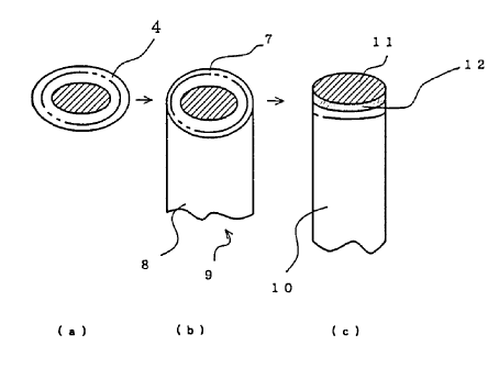
blank 4 as shown in figure 5(a).
The punched blank 4 is drawn by die and punch, and is
formed into the temporary metallic cup 9 which has the bottom 7
with fixed diameter and sidewall 8 with fixed height as shown
in figure 5 (b) .
The metallic cup 9 is redrawn several times and
finally becomes the laminated can 10 which has fixed height and
the diameter shown in figure 5 ( c ) ( ( c ) of chart 5 ) .
I
The higher crystal orientated part 5 corresponds to the
whole bottom 11 and the lower sidewall part 10 of this laminated
can. I This is shown by that the oblique lined part
is extending even to the can sidewall in figure 5(c) (figure
(c) -12) .
Figure 6(a) shows the distinction of each of the
areas. The area indicated by R1 corresponds to the higher
crystal oriented part 5 in laminated sheet 1 shown in figure
6(a). The area shown with R2 corresponds to the lower crystal
oriented part.
The laminated can shown in figure 6(a) is an example
of laminated can of the present invention. The laminated can
is domed at the bottom and the domed part 10A is formed as
shown in figure 6(b). In addition, the laminated can is
- 13 - j
_ ~1~8'~fi3
trimmed, printed, cured, necked, and flanged, and shaped into
the final laminated can.
In case of producing the drawn and ironed can, the
laminated can~is formed by ironing the drawn or redrawn cup.
In ironing as mentioned above, the side wall lOb is severely
processed. Because that part has the lower crystal oriented
resin film, the film adheres well to the metallic substrate.
Therefore, laminated film is not easily de-laminated.
The .bottom 10a and its marginal part often knock
against other cans in transport. That part has higher crystal
i
orientated resin film and has excellent denting resistance. i
Therefore, cracks are not easily caused on the resin film in
the inner wall.
Because the bottom 10a is less processed, de-
lamination is-:not caused even if the laminated film is highly
oriented. Therefore, whole can has excellent durability.
Next, the manufacturing method of the laminated sheet
which has higher and lower crystal orientation in the laminated
i
film of the present invention is explained through the figure 7. I
to 15.
Figure 7 shows a heating roll 21 to heat metal
substrate 2 as strip. A pair of laminating rolls 22 are
i
arranged below the heating roll 21 in order to laminate the
metal substrate 2 and two resin film 3 which locate both side
of .the metallic substrate. A water bath 23 is arranged below i
the pair of laminating rolls 22 to quench the laminated sheet.
After being uncoiled from the uncoiler, the metal
- 14 -
~;I~~'~~~
substrate 2 is heated by the heating roll 21 and turned
downwardly.
In addition, the metal substrate 2 runs through ;
I
between the couple of laminating rolls 22 and enters the water
i
i
bath 23 for quenching. The resin film 3 is supplied from the
i
above part of laminating roll 22 and is laminated to the
metallic substrate 2 by the pair of laminating rolls 22. The
heating roll 21 of the above-mentioned laminating facility has
the shape shown in figure 8.
The heating pipes 24 are arranged in the heating roll
22 to circulate the heating medium such as heated water or oil
in the direction of the roll axis. Those heating pipe 24 are
not passed through area Z which corresponds to the higher
crystal orientated part in the laminated sheet 1 shown in ~'
I
figure 1. That is, heating pipe 24 which penetrates from a w
left axis 25 to the right axis 26 of heating roll 21 passes the
vicinity of surfaces of heating roll 21 except area Z. The
heating pipe 24 passes the center part of the heating roll 21
in area Z and the heat conduction is intercepted by a heat
insulator.
A cooling pipe which sends cooling water to area Z
can be arranged. When the metallic substrate 2 is 'heated by
above heating roll 21, the temperature of metal substrate is
j
raised except in~the part contacting area Z. Therefore, the
crystal orientation of the film decreases at. all parts except
the part contacting area Z when resin film 3 is laminated on
the heated metal substrate 2 and is passed through laminating
_ 15 _
I
rolls 22.
Moreover, the crystal orientation of the film
contacting the area Z is kept near in original orientation.
Therefore, the higher crystal oriented circular part 5 is
partially formed on the laminated sheet 1, and the other area
has the lower crystal orientation.
In order to produce the disk blank pattern when the
higher crystal oriented part 5 is zigzagingly arranged as shown
in figure 1, area Z on the opposite side of the heating roll 21
shown in figure 8 must be located with constant difference in
the direction of the roll axis.
The surface temperature of the above-mentioned
heating roll 21 is different according to the material and the
thickness of resin film 3. For instance, in using bi-axially
oriented polyester film, the higher temperature part is about
210 - 260°C and area Z is~about 170 - 230°C.
The laminating speed is about 150 m/min in the case
of the general laminating method.
An induction heating roll, heating pipe roll or
jacket heating roll can be used as heating roll which heats I
metal substrate 2.
The cooling roll 27 shown in figure 9 partially cools
the metal substrate 2 which is uniformally heated by the above-
mentioned heating roll 21. The cooling roll 27 is arranged on .
the both sides or one side of the metallic substrate 2 below
the heating roll 21 as shown in figure 7. The cooling roll 27
is made of the high heat conductivity metal such as aluminum.
- 16 -
~1~8~fi
A projecting part 28 is arranged on the cooling roll
27 under the uniform pattern. This projecting part 28 contacts
to the metal substrate 2 which has been heated by the heating
roll 21, and cools it. In the case of using this cooling roll
27, the heating roll 21 can be the one which heats whole area
of the metal substrate 2. The pattern of projecting part 28 is
the same as the area shown in figure 8.
Such cooling rolls 27 can also cause the desired
temperature distribution on the surface of the metal substrate
2. And the degree of the crystal orientation of the resin film
3 laminated to the metal substrate 2 can be changed in the
direction of the plane.
l
Figure 10 shows the case where the laminating roll 22
has an insulating part 29 and cooling part 30 on itself. Such !
insulating part 29 can be composed of a rubber lining of the
same type as in a general laminating roll. The cooling part 30
can be composed of an exposed metallic part 31 of the center of
the roll. The cooling part 30 and insulating part 29 have a
continuously smooth~and cylindrical surface. The metallic part
31 in the laminating roll 22 can have a cavity 32 and cooling
medium such as cooling water flows in it.
The cooling roll 27 shown in Figure 9 can be given
the rubber lining same as laminating roll 22 and the surface
temperature of it can be partially changed.
Figure 11 shows the perspective drawing of the
cooling roll 27 shown in figure 9 (or laminating roll shown in
figure 10) to indicate the projecting part 28 (or the cooling
- 17 -
part 30) clearly. The circular projecting part 28 (or the
cooling part 30) is arranged according to the specified pitch P
(see figure 12). The lines of these 'projecting parts 28 are
zigzagingly arranged with constant difference in the direction
of the roll axis.
The metal substrate 2 is partially cooled by the
cooling roll 27. This metal substrate 2 and resin film 3 are
laminated by the pair of laminating rolls 22, and are formed to
the laminating sheet 1 as shown in figure 1. The imaginary
line 33 in figure 11 indicates the outline drawing of the
laminating roll which is covered with rubber. All parts except
the projecting part 28 are insulated by means of the lining
rubber.
Figure 12 shows A -. A line cross section of figure
11. The projecting part 28 (or cooling part 30) is composed of
the cylindrical projection surroundedby tapered face 34. The
diameter D of the projecting part 28 is decided according to
the diameter of the bottom of the laminated can produced by
above-mentioned method.
In the case where the diameter of the blank is 179
mm, for instance, the diameter D of the projecting part 28 . is
65~ mm. For instance, the pitch P is assumed 310 mm. The
height H of the projecting part 28 is about 3 to 5 mm.
Figure 13 shows another example, and laminating roll
22 is the same as a conventional one. The laminating roll 22
is partially cooled by the cooling roll 35. The metal
substrate 2 and resin film 3 are laminated by partially cooled
- 18 -
CA 02168763 1999-11-03
laminating rolls. The construction of the cooling roll
35 is the same as those shown in figures 11 - 12. The
projecting part 35a to cool is arranged on the surface of
the cooling roll 35.
In above examples, the metal substrate 2 is
partially heated by heating roller and partially cooled
by the cooling roll before laminating. Or higher and
lower temperature parts are formed on the metal substrate
in laminating by laminating roll 22.
The imaginary outline S in figure 13 is another
example, and it indicates that the laminated sheet 1 is
partially cooled just after laminating. At that time,
the cooling roll used is the same as above cooling roll
27.
All examples mentioned above indicate the common
method to change the temperature of the metal substrate
or laminated sheet partially and consequently the
distribution of the crystal orientation of the laminated
resin film changes in the planar direction.
Figure 14 shows the outline to produce the laminated
sheet with same property by means of partially changing
the thickness of the resin film 3. Before laminating,
the resin film 3 is heated by preheating roll 36 in
advance and runs through the pair of pattern rolls 37
which have the projecting or depressing parts. As a
result, the thick part 38 and the thin part 39 are formed
in the resin film 3 as shown in figure 15. When such a
resin film 3 and metal substrate 2 are laminated by
conventional laminated roll, the thick part 38 of the
film is not heated sufficiently, so that the thick part
- 19 -
I.
..._ ',
~Z6~'~~3
38 of the film has the higher crystal orientation. On the
contrary, the crystal orientation of the thin part 39 of the
film decreases because that part reaches a high temperature.
The surface of the laminated sheet 1 with thin or
thick part of the resin film 3 is smoothed through the drawing
and ironing as shown in figure 5 whereby roughness of the
laminated film does not stand out.
The thickness of each part of previous resin film is
decided according to the product. Usually the part subject to
denting has a thickness of about 5 to 50% of the original
thickness of the resin film.
Next, a concrete example and a comparison example are
given and the effect of the laminated sheet of the present
invention is explained.
(Example 1)
Tin free steel which was 0.175 mm in th~.ckness and
960 mm in width was used as a metal substrate. Hi-axially
oriented polyethylene terephthalate resin films were laminated
to both side of that metallic substrate by the laminating
apparatus as shown in figure 7. An adhesive of epoxy resin was
provided between the metal substrate and the film. The
thickness of the film was 25 Eun and the thickness of the
adhesive layer was 0.8 ~,m.
At the laminating, the circular low temperature parts
of diameter of 80 mm were zigzagingly arranged by the pitch 131
mm on the heating roll as shown in figure 1.
The other conditions of the laminating were the same
- 20 -
I
as the conventional method.
(Example 2)
In the laminating process, cooling rolls were used.
I
The other conditions were same as example 1, and the laminated.
sheet was produced by means of example 2.
(Example 3)
The cooling part was arranged on the laminating roll.
The other conditions were same as example 1, and the laminated
sheet was produced by means of example 3.
(Comparison example 1)
A polyethylene terephthalate resin film with a high
crystal orientation was laminated to and over the same metallic
substrate as example 1. That laminated film had constant
crystal orientation over all parts.
(Comparison example 2)
A polyethylene terephthalate with a low crystal
orientation such as undrawn film was laminated to the same
metal substrate as example 1. That laminated film had constant
crystal orientation over all parts.
I
- 21 -
v
The above laminated sheet was drawn and redrawn by
means of the method shown in figure 5 and was formed into the
laminated can. The bottom of that can .was 65 mm in diameter.
Whether de-lamination occurred in the laminated can or not was
evaluated by visual observation.
The denting resistance was evaluated by the following
method. The laminated can was filled with water and then the
was seamed on it. In addition, the packed can was dropped from
a height of 15 cm.
The film crack of the dented part was evaluated by
enamel rater value (ERV) measuring method. ERV measuring
method is explained as follows. A brine solution of about 3%
is poured into the above can after it has fallen, dented and
opened. And a stainless steel stick is immersed into it as
cathode.
Next, voltage of 6.3 volt's is applied between the
can which is anode and the stainless steel stick cathode. At
this time. in case of the metal is exposed through the crack in
the film, the current flows between both poles. , ,
The results are shown in table 1.
- 22 -
~~~~~~J
Table I
The degree of de-lamination The denting resistance (ERV current value)
example 1 None 0 (insulated)
example 2 None 0 (insulated)
example 3 None 0 (insulated)
compersion example 1
large de-lamination 0 (insulated)
in upper part of can
compersion example 2
None 1.25 mA
The cans of example 1-3 did not have any de-
lamination and had excellent denting resistance as shown in
table 1. j
On the other hand the can of comparison example 1 had
excellent denting resistance. However, a large de-lamination
occurred in the upper part of the can.
Moreover, a film crack occurred remarkably in the
dented part on the can of comparison example 2 though de-
lamination was not generated.
The laminated resin film which uniformally has the
low crystal orientation has inferior denting resistance and
never de-laminated.
On the contrazy, the laminated resin film which
- 23 -
.
uniformally has the high crystal orientation has superior
denting resistance and de-laminates at much area.
When the laminated sheet which consists of metal
substrate and resin film is drawn or ironed, the extensional
deformation or the shrinkage deformation in the substrate is
caused according to the degree of the processing. Then, if the
lightly crystal oriented part is set to the highly processed
part, the laminated sheet has excellent adhesion. As a result,
de-lamination is hardly caused.
As the laminated resin film was elongated with
metallic substrate, the higher the crystal orientation of the
film becomes, the greater the film is drawn in the processing.
On the contrary, the highly oriented part is set to
the lightly processed part. As a result, the orientation of
the film of the can increases in.a whole can after forming.
That laminated can has excellent denting resistance and
corrosion resistance.
For instance, when the laminated sheet is used as a
material of the two piece can, the film corresponding to the. ,
bottom of the can should have the high crystal orientation.
The film in the sidewall where the degree of the processing. is
high should have the low crystal orientation.
When the resin film which has high crystal
orientation is laminated to the metal substrate, and high and
low temperature part were given to the metal subs-trate or
laminating roll, the crystal orientation of the film which
contacts with the high temperature part decreases. And the
- 24 -
crystal orientation of the film which contacts low temperature
part is kept as original.
The same effect is achieved also when the laminated
sheet passes through the laminating roll cooled partially.
When the temperature of the film partially changes according to i
fixed pattern, the same effect is achieved. The resin film
which has the high orientation is preheated and the thin or
thick part is formed immediately before laminating. Then the
temperature of the thin part rises and the crystal orientation
i
decreases. On the contrary, the temperature of the thick part
does not rise so much and the crystal orientation is kept as
original.
Industrial possibility
The laminated sheet of the present invention has the
highly or lightly crystal oriented part of the resin film
according to the fixed pattern.
The de-lamination of the film is suppressed and the '
denting resistance of the can is superior.
The laminated sheet of the present invention is for
the use of can manufacture , and de-lamination of the severely
i
processed aide wall is suppressed.
Moreover the bottom of the can has excellent denting
resistance.
When the resin film is laminated to the metal
substrate, the pattern of the high crystal orientation of the
film can be set according to the manufacturing method of the
present invention.
- 25 -
I;
y
Su~arv
The laminated sheet of the present invention consists
of the metallic substrate and oriented thermoplastic resin
f ilm,
and the laminated film has the high or low crystal orientated
part in the plane direction according to uniform pattern.
Therefore, the low orientated part corresponding to
the sidewall of the can has excellent formability and the high
orientated part corresponding to the bottom has excellent
denting resistance.
The manufacturing method of the present invention is
about the laminating process.
When the metallic substrate and the resin film are
laminated, the any pattern of the high crystal
orientation of the laminated film can be set.
- 26 -