Note: Descriptions are shown in the official language in which they were submitted.
VO95/03747 2 1 6 ~ 7 8 9 PCT~S94/08458
-
--1--
SEGMENTED PLIABLE INTRASTROMAL CORNEAL INSERT
Field of the Invention
This invention is a pliable intrastromal
corneal insert designed to be inserted into an
interlamellar channel made within the cornea of a
mammalian eye. It is made of a physiologically
compatible polymer and may be used to adjust corneal
curvature and thereby correct vision abnormalities. The
insert or segment may also be used to deliver therapeutic
or diagnostic agents to the corneal interior or to the
interior of the eye. The insert subtends at least a
portion of a ring, or "arc", encircling the anterior
cornea outside of the cornea's field of view but within
the cornea's frontal diameter, but may be used in
multiples to form complete arcs or to form constructs of
varying thickness. The invention also includes both a
minimally invasive procedure for inserting one or more of
the devices into the cornea as well as the thus-corrected
eye.
Backqround of the Invention
Anomalies in the overall shape of the eye can
cause visual disorders. Hyperopia ("farsightedness~')
occurs when the front-to-back distance in the eyeball is
too short. In such a case, parallel rays originating
greater than 20 feet from the eye focus behind the
retina. In contrast, when the front-to-back distance of
eyeball is too long, myopia ("nearsightedness") occurs
and the focus of parallel rays entering the eye occurs in
W095/03747 PCT~S94/084
2l687 89 -2-
front of the retina. Astigmatism is a condition which
occurs when the parallel rays of light do not focus to a
single point within the eye, but rather have a variable
focus due to the fact that the cornea refracts light in a
different meridian at different distances. Some degree
of astigmatism is normal, but where it is pronounced, the
astigmatism must be corrected.
Hyperopia, myopia, and astigmatism are usually
corrected by glasses or contact lenses. Surgical methods
for the correction of such disorders are known. Such
methods include radial keratotomy (see, e.g., U.S.
Patents Nos. 4,815,463 and 4,688,570) and laser corneal
ablation (see, e.g., U.S. Patent No. 4,941,093).
Another method for correcting those disorders
is through the implantation of polymeric rings
(intrastromal corneal rings or "ICR's") in the eye's
corneal stroma to change the curvature of the cornea.
Previous work involving the implantation of
polymethylmethacrylate (PMMA) rings, allograft corneal
tissue, and hydrogels is well documented. One of the
ring devices involves a split ring design which is
inserted into a channel previously dissected in the
stromal layer of the cornea. A minimally invasive
incision is used both for producing the channel and for
inserting the implant. See, for instance, the use of
PMMA intrastromal rings in U.S. Patents Nos. 4,452,235 to
Reynolds; 4,671,276 to Reynolds; 4,766,895 to Reynolds;
and 4,961,744 to Kilmer et al. These documents suggest
only the use of ICR's which completely encircle the
cornea.
The use of soft polymers as intrastromal inserts
is not widely known. For instance, U.S. Patent No.
5,090,955 to Simon, suggests an ICR which is made by
introducing a settable polymer or gel into an
intrastromal channel which has been previously made and
~Og5lo3747 216 8 7 8 g PCT~S94/08458
--3--
allowing the polymer to set. This procedure does not
allow the surgeon to specify the precise size of the
resulting ring nor is it a process which allows precise
control of the pathway of the flowing polymer within the
eye since the gel must simply conform to the shape of the
intrastromal channel. However, it does show the concept
of using arcuate channels containing a gel-based insert
centered about the corneal.
Temirov et al, "Refractive circular tunnel
keroplasty in the correction of high myopia", Vestnik
Oftalmologii 1991: 3-21-31, suggests the use of collagen
thread as ICR material.
These publications do not suggest the
introduction of pliable polymeric inserts into the cornea
for the correction of various visual aberrations. The
publications do not imply that the devices may be used to
introduce therapeutic or diagnostic materials into the
corneal intrastromal space.
SummarY of the Invention
This invention is a method of inserting a
pliable polymeric insert into a cavity formed between the
lamella of the corneal stroma. The insert is of a
selected size and composition and will, after insertion
into the interlamellar channel, conform to the shape of
the channel and alter the anterior shape of the cornea.
It need not conform to the intrastromal channel shape
prior to insertion. The inserts may be used in
isolation, in isolated multiples, in cooperative
multiples, or as segments in a larger assemblage
encircling at least a portion of the cornea. The insert
may be of one or more synthetic or natural polymers,
hydrophilic or hydrophobic, or may be a hybrid device
- comprising layered materials. Optionally, the insert may
contain filamentary material in the form of a single or
W095/03747 ~6~ r~ PCT~S94/084'
--4--
multiple threads, random included filaments, or woven
mattes to reinforce the insert during, e.g., insertion or
removal from the intrastromal channel.
The insert may be hollow and may be filled with
a biologic agent, drug or other liquid, emulsified, or
time-release eye treatment or diagnostic material. The
insert may contain a gel, viscous, or visco-elastic
material which remains in such a state after
introduction
When a hybrid, the inner portion may comprise
variously a composite of low modulus polymers or a single
low modulus polymer. The inner portion may also comprise
a polymeric material which is polymerized in situ after
introduction into the hollow center layer. The inserts
may be trimmed from a larger or longer insert prior to or
after insertion into the eye. The larger precursor may
be of a constant size or diameter or may be of a variable
size or diameter. The variable size or diameter insert
precursor allows the surgeon to select a size which will
make the necessary visual correction. The long precursor
may then be clipped and removed.
These inventive segmented inserts may be
introduced into the corneal stroma using techniques
involving the steps of providing an intrastromal channel
which traverses at least a portion of the circumcorneal
rotation. Specific indications, such as astigmatism, may
be rectified by insertion of one or more of the inserts
into a partial intrastromal channel to flatten the
steeper portions of the anterior corneal surface without
insertion of a complete intracorneal ring (ICR).
If hydratable polymers are used, they may be
hydrated before or after introduction into the
intrastromal passageway created by the surgical device
used to introduce these devices into the eye. If the
outer layer is hydrated before insertion into the eye,
_ WO95/03747 21 6~ 789 PCT~S94/08458
the final size of the insert is set before that
insertion. If the hydratable polymers are allowed to
hydrate within the corneal space, the device (if
appropriate polymers are chosen) will swell within the
eye to its final size. If prehydrated, the outer layer
often provides a measure of lubricity to the device,
allowing it to be inserted with greater ease. Other of
the noted low modulus polymers may also provide such
lubricity.
Brief Description of the Drawinqs
Figure 1 is a schematic illustration of a
horizontal section of the eye.
Figure 2 is a schematic illustration of the
anterior portion of the eye showing the various layers of
the cornea.
Figures 3A and 3B show respectively a front
view and a cross section of a typical intracorneal insert
made according to the invention.
Each of Figures 4A and 4B, 5A and 5B, 6A and
6B, and 7A and 7B, shows respectively a front view ("A"
drawing) and a cross section ("B" drawing) of various
intracorneal inserts made according to the invention.
Each of Figures 8A and 8B and 9A and 9B shows
respectively a front view ("A" drawing) and a cross
section ("B" drawing) of various intracorneal inserts
having filamentary reinforcing made according to the
invention.
Figures 10A and 10B show respectively a front
view and a cross section of a soft, filled intracorneal
insert made according to the invention.
Figure 11 depicts a front view of an end-to-end
assemblage of intracorneal segments placed within a human
cornea.
W095/03747 2 16 8 ~ 8 3 6- PCT~S94/0845
Figure 12 shows an assemblage of intrastromal
segments joined with a clasp.
Figures 13A and 13B show top and side views of
overlapping segments.
s Figures 14A-14E and 15A-15F show schematic
processes for introducing multiple inserts into the human
cornea.
Figure 16A shows an insert precursor having a
variety of diameters. Figures 16B-D schematically show a
procedure for use of the insert precursor shown in Fig.
16A.
Description of the Invention
Prior to explaining the details of the
inventive devices, a short explanation of the physiology
of the eye is needed to appreciate the functional
relationship of these intracorneal inserts or segments to
the eye.
Figure 1 shows a horizontal cross-section of
the eye with the globe (110) of the eye resembling a
sphere with an anterior bulged spherical portion
representing the cornea (121).
The globe (110) of the eye consists of three
concentric coverings enclosing the various transparent
media through which the light must pass before reaching
the light-sensitive retina (182). The outermost covering
is a fibrous protective portion the posterior five-sixths
of which is white and opaque and called the sclera (13),
and sometimes referred to as the white of the eye where
visible to the front. The anterior one-sixth of this
outer layer is the transparent cornea (12).
A middle covering is mainly vascular and
nutritive in function and is made up of the choroid,
ciliary body (15), and iris (17). The choroid generally
functions to maintain the retina (18). The ciliary body
_ W095/03747 2~ 6~ PCT~S94/08458
(16) is involved in suspending the lens (21) and
accommodation of the lens. The iris (17) is the most
anterior portion of the middle covering of the eye and is
arranged in a frontal plane. It is a thin circular disc
similar in function to the diaphragm of a camera, and is
perforate near its center by a circular aperture called
the pupil (19). The size of the pupil varies to regulate
the amount of light which reaches the retina (18). It
contracts also to accommodation, which serves to sharpen
the focus by diminiching spherical aberration. The iris
divides the space between the cornea (12) and the lens
(21) into an anterior chamber (22) and the posterior
chamber (23). The innermost portion of covering is the
retina (18), consisting of nerve elements which form the
true receptive portion for visual impressions.
The retina (18) is a part of the brain arising
as an outgrowth from the fore-brain, with the optic nerve
(24) serving as a fiber tract connecting the retina part
of the brain with the fore-brain. A layer of rods and
cones, lying just beneath a pigmented epithelium on the
anterior wall of the retina serve as visual cells or
photoreceptors which transform physical energy (light)
into nerve impulses.
The vitreous body (26) is a transparent
gelatinous mass which fills the posterior four-fifths of
the globe (11). At its sides it supports the ciliary
body (16) and the retina (18). A frontal saucer-shaped
depression houses the lens.
The lens (21) of the eye is a transparent bi-
convex body of crystalline appearance placed between theiris (17) and vitreous body (26). Its axial diameter
varies markedly with accommodation. A ciliary zonule
(27), consisting of transparent fibers passing between
the ciliary body (16) and lens (121 serves to hold the
-
WO95l03747 ` 2 ~ 6 8 7 ~ 9 PCT~S94/084~
lens (21) in position and enables the ciliary muscle to
act on it.
Referring again to the cornea (12), this
outermost fibrous transparent coating resembles a watch
glass. Its curvature is somewhat greater than the rest
of the globe and is ideally spherical in nature.
However, often it is more curved in one meridian than
another giving rise to astigmatism. A central third of
the cornea is called the optical zone with a slight
flattening taking place outwardly thereof as the cornea
thickens towards its periphery. Most of the refraction
of the eye takes place through the cornea.
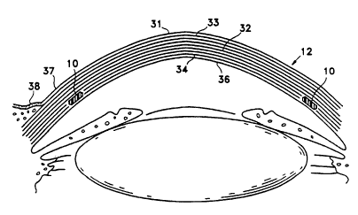
Figure 2 is a more detailed drawing of the
anterior portion of the globe showing the various layers
of the cornea (12) making up the epithelium (31).
Epithelial cells on the surface thereof function to
maintain transparency of the cornea (12). These
epithelial cells are rich in glycogen, enzymes and
acetylcholine and their activity regulates the corneal
corpuscles and controls the transport of water and
electrolytes through the lamellae of the stroma (32) of
the cornea (12).
An anterior limiting lamella (33), referred to
as Bowman's membrane or layer, is positioned between the
epithelium (31) and the stroma (32) of the cornea. The
corneal stroma (32) are made up of lamellae having bands
of fibrils parallel to each other and crossing the whole
of the cornea. While most of the fibrous bands are
parallel to the surface, some are oblique, especially
anteriorly. A posterior limiting lamella (34) is
referred to as Descemet's membrane It is a strong
membrane sharply defined from the stroma (32) and
resistant to pathological processes of the cornea.
The endothelium (36) is the most posterior
layer of the cornea and consists of a single layer of
-
_ ~Q95tO3747 21 68 7S PCT~S94/084S8
_g _
cells. The limbus (37) is the transition zone between
the conjunctiva (38) and sclera on the one hand and the
cornea (12) on the other.
Figure 3A shows a front view of one variation
of an insert made according to the invention and Figure
3B shows a cross section of that insert. These segments
are suitable for insertion into the appropriately
prepared interlamellar, intrastromal, intracorneal
channel. Generally, the intrastromal segment is
installed into the eye in the following manner: A small
radial incision is made at the corneal radius at which
the intrastromal segment is ultimately to be installed
about the cornea. A dissector in the form of a split
ring having a point suitable for producing the
interlamellar channel in the corneal stroma is introduced
into the stromal space through the small incision. The
dissector is then rotated in such a fashion that a
generally semicircular or arc-shaped channel is formed at
least partially circling the cornea at the chosen radius.
After a channel of the proper length is achieved, the
cutting step is concluded. The dissector is then rotated
in the opposite direction to withdraw it from the tunnel
or channel thus formed. As is explained in more detail
below, a pliable intrastromal segment is then introduced
into the channel.
As is shown in Figure 3A, the segment (100),
after it is inserted into the eye, conforms to the shape
of the intrastromal channel subtending some specific
portion of the circumference of the cornea equal to a
value of "~", which value is typically up to 360, but
preferably less than 320, most preferably less than
270. I refer to this angle as the "arc angle". The
value of "~" is dependent upon the indication to be
resolved and the physical arrangement of the sector (or
sectors) as they are installed in the eye. For instance,
WOg5/03747 2 ~ 6 8 7 8 9 PCT~S94/084'
--10--
often the value of "~" is 20 to 90 for the correction of
modest astigmatic aberrations resulting in astigmatism.
Similarly, if the segments are used in conjunction with
each other such as is described below, the value of "~"
may be any of a wide range of values. In any event, for
definitional purposes, the opposite ends of a single
"segment" do not meet when the segment is inserted into
an intrastromal channel. However, as described below,
the ends of a segment may overlap with the end of another
segment, may abut another segment, or may be parallel
with another segment when they are placed in an
intrastromal channel.
Figure 3B shows the cross section of the
sector. For convenience, the chosen conventions for
thickness and width are shown on Figure 3B.
The typical width is often between 0.005 inches and
0.250. The typical thickness is often between o.oos
inches and 0.080 inches. Both of these parameters (along
with certain other variables such as the cross-sectional
shape of the device and its constituent polymers)
determine, in large part, the level of correction
achievable by use of the insert.
The devices of this invention are pliable. By
"pliable", I mean that the device, prior to its insertion
into the eye, is quite flexible and desirably is not
preformed to the shape of the intrastromal channel noted
above. Specifically, and most desirable, "pliable" means
that the device is transformed from a previous shape
(that prior to insertion into the intrastromal channel)
into the shape of the intrastromal channel only by
imposition of the force inherently found in the channel
walls.
The materials used in these inserts may be
physiologically acceptable, low modulus polymers, e.g.,
those having a modulus of elasticity below about 3.5
_ W095/03747 216~ 7~ PCT~S94/08458
--11--
kpsi, more preferably between 1 psi and 1 kpsi, and most
preferably between 1 psi and 500 psi, which are
physiologically compatible with the eye. Most polymeric
materials used in soft contact lenses are suitable the
segments of this invention. The class includes
physiologically compatible elastomers and such
crosslinked polymeric gels as polyhydroxyethyl-
methacrylate (Poly-HEMA) or polyvinylpyrrolidone (PVP),
polyethylene oxide, or polyacrylates, polyacrylic acid
and its derivatives, their copolymers and interpolymers,
and the like as well as biologic polymers such as
crosslinked dextran, crosslinked heparin or hyaluronic
acid.
In many instances, the intrastromal segments
may be hybrid, that is to say, the segments are made up
of a number of polymeric layers often with a soft or
hydratable polymer on their outer surface. These hybrid
segments will be described with greater particularity
below. Partially hydrated or fully hydrated hydrophilic
polymers are typically slippery and consequently may
contribute to the ease with which the insert may be
introduced into the interlamellar tunnel. It is usually
desirable to (at least partially) hydrate the hybrid
intrastromal segment in that, otherwise, the intrastromal
segment during its traverse through the tunnel may
desiccate the path and begin to stick to the interior
wall of the tunnel.
The intrastromal segments may be lubricated
with suitable ocular lubricants such as hyaluronic acid,
methylethyl cellulose, dextran solutions, glycerine
solutions, polysaccharides, or oligosaccharides upon its
introduction to help with the insertion particularly if
one wishes to insert intrastromal segments of hydrophilic
polymers without prior hydration. If a hybrid segment
having a hydrophilic polymeric covering or a segment
WOg5/03747 216~ ~ PCT~S94/0845
-12-
comprising a hydrophilic polymer is inserted into the eye
without prior hydration, subsequent to the insertion, the
intrastromal segment will swell to its final size or
thickness within the eye. This swelling often permits
the inclusion of larger intrastromal segments than would
normally be accommodated within normal sized intrastromal
channels.
Low modulus polymers used in this invention are
often absorbent, particularly if they are hydratable, and
may be infused with a drug or biologic agent which may be
slowly released from the device after implantation of the
intrastromal segment. For instance, the low modulus
polymer may be loaded with a drug such as dexamethasone
to reduce acute inflammatory response to implanting the
device. This drug helps to prevent undesirable scarring
or vascular ingrowth toward the intrastromal segment.
Similarly, heparin, corticosteroids, antimitotics,
antifibrotics, antiinflammatories, anti-scar-forming,
anti-adhesion, and antiangiogenesis factors (such as
nicotine adenine dinucleotide (NAD+)) may be included to
reduce or prevent angiogenesis and inflammation.
Clearly, there are a variety of other drugs
suitable for inclusion in the intrastromal segment. The
choice will depend upon the use to which the drugs are
put.
Each of Figures 4A and 4B, 5A and 5B, 6A and
6B, and 7A and 7B show respectively a front view ("A"
drawing) and a cross section ("B" drawing) of various
intracorneal inserts suitable for use in the inventive
method-
Figure 4A shows a front view of an intracornealinsert (100). Viewed in cross section in Figure 4B, the
generally smooth convex front surface (102) and planar
rear surface (104) may be seen.
~ ~095/03747 2 1 6 8 7 ~ ~ PCT~S94/08458
Figure 5A shows a front view of an intracorneal
insert (108). As with the devices shown in Figures 4A
and 4B, the intracorneal inserts may taper either or both
in width and in thickness or may have blunt, non-trimmed
ends. Viewed in cross section in Figure 5B, the
generally hexagonal shape may be seen. The generally
planar front surface (110) and planar rear surface (112)
may be seen. Our previous experience with IntraCorneal
Rings ("ICRs't) has demonstrated that the use of such a
shape in the cornea is generally less traumatic than one
of a rectangular cross section and yet, because of the
similarity of the shape to that of the intrastromal
formed by the blade producing the channel, is often
considered to be the maximum cross sectional volume
achievable in such configuration.
Figure 6A shows a front view of an intracorneal
insert (114). Figure 6B shows the generally round cross
section. The cross section may also be oval-shaped with
the major axis of the oval either as the width or the
thickness or neither.
Figure 7A shows a front view of a hybrid
intracorneal insert (116). Viewed in cross section in
Figure 7B, the generally hexagonal shape may be seen.
This set of Figures is to show the concept of a
multilayered insert made up of polymers of different
characteristics. In this example of a multi-layered
insert, the hybrid intrastromal segment has inner (118)
and outer faces (120) of polymers having low moduli of
elasticity. Low modulus polymers are those having a
modulus of elasticity below about 3.5 kpsi, more
preferably between 1 psi and 1 kpsi, and most preferably
between 1 psi and 500 psi. They must be physiologically
compatible with the eye. As was noted above, this class
- of polymers includes most polymeric materials used in
soft contact lenses.
W095/03747 2 ¦ 6 8 7 8 9 PCT~S94/084:
-14-
The inner portion or core (122) as shown in
Figure 7B may also be a physiologically compatible
polymer having a low modulus of elasticity.
If hydratable polymers are chosen for the
outside layers, the extent to which those outer layers
swell upon hydration is dependent upon the type of
polymer chosen and, when the polymer is hydratable, upon
the amount of cross-linking found in the outer layers
(118) and (120), and upon the thickness of the layer.
Generally speaking, the more highly linked the hydratable
polymer, the smaller the amount of volume change upon
hydration. Conversely, a polymer having only sufficient
cross-linking for strength in the service in which this
device is placed, will have a somewhat lower level of
cross-linking. Alternatively, a substantially
nonswellable polymer system may be formed of a hydrogel
physically interpenetrated by another polymer which does
not hydrate. Suitable hydrophilic polymers include
polyhydroxyethylmethacrylate (pHEMA), N-substituted
acrylamides, polyvinyl pyrrolidone (PVP), polyacrylamide,
polyglyceryl methacrylate, polyethylene oxide, polyvinyl
alcohol, polyacrylic acid, polymethacrylic acid,
poly(N,N-dimethylaminopropyl-N'-acrylamide) and their
copolymers and their combinations with hydrophilic and
hydrophobic comonomers, crosslinks, and other modifiers.
Thermoplastic hydrogels include hydropolyacrylonitrile,
polyvinyl alcohol derivatives, hydrophilic polyurethanes,
styrene-PVP block copolymers and the like.
The thickness of the outer layer depends in
large function upon the intended use of the intrastromal
segment. If the outer layer is used to provide a
swellable outer layer which does not add significantly to
the size of the intrastromal segment or is used
functionally as a lubricant layer, the other layer may be
_ W095/03747 21 6~ 7~9 ~CT~S94/08458
quite thin even to the point of a layer of minimum
coverage, perhaps as thin as a single molecule.
of course, the inner and outer layers may be
multiple layers of low modulus polymers including an
outer hydrophilic polymer layer and an inner hydrophobic
polymer; a variety of hydrophilic polymers; etc.
Additionally, the inventive device shown in
Figures 7A and 7B need not have inner (118) and outer
(120) layers over the entire intrastromal segment. For
instance, to alleviate astigmatism, an intrastromal
segment having a thicker portion and a substantially
thinner portion may be desired. An intrastromal segment
having an inner core of a low modulus polymer and an
outer covering of a swellable polymer might be chosen.
The eye surgeon would remove a portion of the
intrastromal segment's exterior coating or face prior to
introducing the intrastromal segment into the eye.
Further, and as will be discussed below in greater
detail, hydrophilic polymers are more easily infused with
therapeutic and diagnostic materials than are the high
modulus materials. In the variation just noted, the
insert may then be used to deliver the infused
therapeutic and diagnostic materials in a greatly
delimited treatment or diagnostic area.
Figure 8A shows a front view of an intracorneal
insert (124). In this variation, the insert includes at
least one flexible, longitudinal, filamentary inclusion
to provide a measure of axial strength during the
insertion procedure. The filamentary inclusion (126) may
be seen in cross section in Figure 8B. A generic cross-
sectional shape is depicted in Figure 8B. The
filamentary inclusion (126) is shown with a loop (128)
for attachment to an insertion tool. The loop (128) is
optional and may be omitted depending upon the manner in
which the insert is to be inserted. The filamentary
WO 95/03747 2 ~ 6 8 7 & 9 PCT/US94/084!
inclusion (128) may be produced from a wide variety of
bio-compatible materials including Kevlar, Dacron, etc.
Additionally, the filamentary material may be placed
within the insert in a random fashion.
s Figure 9A shows a partial cross-section, front
view of an intracorneal insert (132). In this variation,
the insert includes a flexible, fabric inclusion (132) to
provide axial strength during the insertion procedure.
The inclusion (132) may be seen in cross-section in
Figure 9B. A generic cross-sectional shape is depicted
in Figure 9B. The fabric inclusion (132) may also be
produced from a wide variety of bio-compatible materials
including Kevlar, Dacron, etc. A loop (not shown) as
shown for the variation found in Figure 8A and 8B,may
also be included for ease of insertion if so desired.
The variations shown in Figures 8A, 8B, 9A, and
9B may be of virtually any cross-section which will
conform to the shape of the intrastromal channel upon
insertion. Methods of binding the low modulus polymeric
coating to the filamentary or fabric inclusion are well
known and need not be described in detail here. Such
methods include molding the filament or fabric in place
or using an adhesive or intermediate polymeric tie-layer
to assure contact and adherence of the fabric to the
outer polymeric layer or layers.
Figure 10A is a front quarter view of a
variation of the intrastromal segment (134) made of a low
modulus polymer system hydratable outer coating (136).
Figure 10B shows the inner cavity (138). This
intrastromal segment may be inserted into the
intrastromal space created by the dissector as a covering
on a tool similar to the dissector which created the
intracorneal channel. Once in position the insertion
tool is rotated out of the intrastromal segment leaving
the shell within the stroma.
WOg5/03747 216(~ 7~9 PCT~S94/08458
-
-17-
Figure 10 shows the inner cavity (138) which
may be filled with a biologic, a drug or other liquid, or
biologically active eye treatment material. These
devices may be tied or pinched or crimped or otherwise
connected at their point of insertion by known
techniques.
The shell (136) may be injected with a gel or
with a settable soft polymer core, allowed to expand to a
desired thickness, and set. Polymeric gels which do not
polymerize in situ are preferred. Suitable injectable
polymers are well known but include polyHEMA hydrogel,
cross-linked collagen, cross-linked hyaluronic acid,
siloxane gels, and organic-siloxane gels such as cross-
linked methyl vinyl siloxane gels.
Figure 11 shows a variation of the invention in
which an assemblage of the inventive intrastromal
segments (140) are formed into a polymeric ring or, at
least, into an assemblage within the intracorneal space.
The two segments (140) depicted in Figure 11 may be of
any of the individual variations shown in the Figures
above and need not be connected in any way. The segments
may be of similar or quite different configurations
depending upon the indication to be remedied.
Additionally, they may be inserted in separately produced
intrastromal channels which may, or may not, be in
communication within the cornea. Such individual
insertion will be discussed in more detail below.
Figure 12 shows a similar assemblage in which
the intracorneal segments (142) are held together using
open holes (144) and a clip (146) which may be a simple
wire or other suitable j oining device. An assemblage
such as is seen in Figure 12 may be advantageously
inserted from a single central opening, as will be
- described below.
WO95/03747 PCT~S94/084'
2~68~ ~9 -18-
Figures 13A and 13B show a variation of the
inventive intracorneal inserts in which two or more
inserts overlap to form an assemblage. The top view
shown in Figure 13A depicts the assemblage of segment
(148) and segment (150) meeting at junction (152) as
found in the eye. The assemblage need not be formed of
segments of the same or similar width or thickness or
material of construction nor need the assemblage be
limited to tXe semicircle shown in Figure 13A. Although
a front-to-back assemblage of is depicted in Figure 13B,
the junction (150) between the sections (148 & 150) may
be of any other design which is allows contact between
the adjoining sections and remains relatively immobile
after the placement in the cornea. The intrastromal
channel normally exerts significant force against the
assemblage and will maintain the sectors in the depicted
relational position within the eye.
The ends of the inserts may be substantially
overlapped so to form a thick insert for the overlapping
area so to correct an astigmatic problem. The inserts
may completely overlap within a channel. The two inserts
may be of differing crop sections or diameters. Further,
rather than overlapping, the inserts may actually be
stacked one on top of the other.
Figures 14A-14E schematically portray a method
for the insertion of the segments described above in
which partial arc segments are introduced into separate
sections of the corneal circumference outside of the
"sight" area of that cornea.
In Figure 14A, the frontal shows the iris (200)
and the pupil (202), As was described above, the cornea
is clear and is not visible in these drawings. Insertion
of the inventive device is a reasonably simple surgical
procedure. An entry slit (204) is made radially into the
cornea. A dissector blade is introduced into the entry
_ W095/03747 _19_ 7~9 PCT~S94108458
slit (204) and turned in the direction of the arrow (206)
to form a partial intrastromal channel of a desired
length. As is then shown in Figure 14B, second entry
slit (208) may then be made in the cornea and a second
intrastromal channel be made in the direction of the
arrow (210).
Figure 14C shows the introduction of the first
inventive segment (212) into the first entry slit (208).
Figure 14D shows the first segment (212) in its final
resting position and the introduction of the second
segment (214) into the second entry slit (208). Finally
Figure 14E shows both first segment (212) and second
segment (214) in their final position within the cornea.
This demonstrates the flexibility of the procedure in
that either left or right "hand" insertion is appropriate
and the intrastromal channel need ont be a complete
circle about the cornea. Further, it should be noted
that the first segment (212) and second segment (214) may
be of differing diameters or of differing arc lengths
depending upon the indication to be resolved.
Figures 15A-15F schematically portray a method
for the insertion of the segments described above in
which partial arc segments are introduced into separate
sections of the corneal circumference outside of the
"sight" area of that cornea through a single entry slit.
Figure 15A shows the making of the initial
entry slit (220) radially into the cornea. A dissector
blade is introduced into the entry slit (220) and turned
in the direction of the arrow (222) to form a partial
intrastromal channel of a desired length. As is shown in
Figure 15B, a second intrastromal channel is made in the
- direction of the arrow (224) from the same entry slit
(222).
Figure 15C shows the introduction of the first
segment (226) into the entry slit (222). Figure 15D
W095/03747 2 16 8 q ~ 9 - 20- PCT~S94/084
shows the f irst segment (226) in its f inal resting
position. Figure 15E shows the introduction of the
second segment (228) into the entry slit (220). Finally
Figure 15F shows both first segment (226) and second
segment (228) in their final position within the cornea.
Because of the nature of these pliable inserts,
a large measure of adaptability is available in the
process of inserting the devices. For instance, I have
found that when using various pliable inserts
(particularly with ocular lubricants) that the inserts
may be "pushed" nearly 180 around a previously created
intrastromal channel for insertion and then easily
removed, if so desired. This observation means that the
following procedure may be used. The eye of a person
having myopia and/or astigmatism may be measured to
determine the proper amount of correction needed. From
this information, the size and placement of one or more
segments may then be chosen. For instance, the selected
sections might be two inserts of 30 arc angle and 100
mils x 100 mils cross-section at two opposing meridians.
After insertion in the appropriate channels, the vision
of the eye might again be measured. If insufficient
correction of an indication is found, the insert may be
withdrawn and a larger size selected and inserted. If an
astigmatic aberration is introduced, the insert may be
withdrawn (partially or completely) and trimmed prior to
complete re-insertion. Such adjustability is not
normally available when dealing with gel-based rings or
with surgical tPch~iques based on radial keratotomy.
Figure 16A shows a pliable insert precursor,
which may be trimmed prior to or after insertion into the
intrastromal channel. In this instance, the insert
precursor (300) is made up of a number of sections --
three are illustrated in Figure 16A although such is not
necessary -- of differing size cross-sections, which
~o95/03747 21 6~ 7 ~ 9 PCT~S94/08458
cross-sections increase in steps along the axis of the
insert precursor. The relative cross-sectional area of
small section (302) is smaller than that of the mid-
section (304) which, in turn, is smaller than that of the
large section (306). A section (308) is of any
convenient length but normally need not be much longer
than the length of a intrastromal channel formed within
the circumference of the cornea. It may be of a shorter
length if so desired.
Figures 16B-16D show one method for
introduction of the precursor insert into a partial
intrastromal channel forming an arc of about 120. In
this illustrative example, two small radial incisions
(310 and 312) have been made and an intrastromal channel
(314) made between the two incisions (310 and 312). The
insert precursor (300) is introduced into one of the
incisions (310) and, as is shown in Figure 16C, out of
the other incisions (312). In this example the proper
amount of astigmatic correction was provided by the mid-
section of the insert precursor (300), and so the
precursor was slid through the intrastromal channel until
the small section (312) protruded out of the incision
(312). Figure 16D shows that the protruding small
section (302) and large section (306) are snipped,
leaving the mid-section in the intrastromal channel. The
incisions (310 and 312) may be sutured shut.
This arrangement, as is shown in Figures 16B-
16D, might be used to correct an astigmatism. However,
the procedure could just as easily be used within an
intrastromal channel which completely encircles the
cornea .
The inserts may be useful in the treatment of
astigmatism, myopia, or the combination of the two. In
each case, segments of differing arc length are
preferred. For the treatment of astigmatism where no
W095/03747 ~6~ -22- PCT~S94/084
myopic correction is needed, segments of between about
20 and 90, preferably between about 20 and 60 may be
used. Where treatment of astigmatism and myopia is
required, segments of between about 45 and 160,
preferably between about 60 and 90 may be used. Where
the treatment of myopia where no astigmatic enhancement
is required, segments of between about 90 and 360,
preferably between about 90 and 270 may be used.
The terms and expressions which have been used
in the description above are used only as terms of
description and not of limitation. There is no intention
of excluding equivalents of the features shown or
described. It is recognized that one having ordinary
skill in this art would perceive equivalence to the
inventions claimed below, which equivalence would be
within the spirit of the invention as expressed above.