Note: Descriptions are shown in the official language in which they were submitted.
wos5/~ss PCT~S94/089~
2~792 ~ ,
-- 1 --
DE8CRIPTION
---DEVICE FOR MoNlToRlNG INTRAOCULAR AND BLOOD PRESSURE---
BACRGRO~ND OF THE INVENTION
I. Field of the Invention
-- .
The present invention relates to methods and apparatus
for non-contact measurement of internal pressure changes in
physiological vessels or cavities.
II. Back~rG~d
Devices which measure blood pressure or the internal
pressure of a physiological vessel or cavity are well known
in the art. For example, devices used for measuring blood
pressure in clinics or offices are generally known as
sphygmomanometers, while those measuring fluid pressure
within an eye are generally known as tonometers. The
latter instruments meas~re the amount of tension on the
eye's outer wall, allowing determination of fluid pressure
within the eye. In order to measure outer wall tension,
conventional tonometers often must have direct or indirect
physical access to the outer wall to deform, displace or
oscillate the outer wall. Analogously, measurement of
blood pressure in most clinical situations requires
application of an inflatable cuff to an arm or leg. In
either case, special equipment is needed and, particularly
in the case of tonometry measurements, the patient must
visit a clinic or office for the measurement to be made.
Tonometry Principles
In general, most tonometers in use today work on
either of two principles. The first principle involves
wog5/~4s5 PCT/US94/08912
~168792 ,,
applying a known pressure or force upon the wall and
measuring the deformation produced. Instruments embodying
this principle are known as impression or indentation
tonometers. The second principle involves applying a known
deformation upon the wall and measuring the force required
to produce the deformation. Instruments using the second
principle are called applanation tonometers. Under either
principle, the wall must be physically manipulated, either
by direct physical contact, such as with a probe or
plunger, or by indirect contact, such as with an air puff
or oscillating air stream.
Conventional tonometers are most often used for
measuring intraocular pressure (IOP) by directly or
indirectly flattening a pre-determined area of the cornea
or the sclera. It is emphasized that though the normal
usage is for the pressure discussed here to be referred to
as intraocular pressure that it is actually the
differential pressure between the inside of the eye and the
ambient pressure outside. This differential pressure is
consistent with results from conventional tonometry means.
In order to contact these areas, the patient's eyes must be
closely aligned with the tonometer so that accurate
readings can be made. Such a procedure often involves a
visit to a physician's office where a skilled operator
performs the test. Furthermore, the operator may have to
anesthetize the eye causing injuries to go undetected while
the eye is under anesthetic.
Need for Re~eat Measurements
Compounding these difficulties is the requirement for
repeat measurements of both IOP and blood pressure (BP) to
clinically follow the course and treatment of disease. The
clinical value of any single measurement of IOP or BP may
be reduced because long-term (e.g., weeks to months)
pressure trends are always superimposed on shorter-term
WOg5/~95 2~ 6~ 792 PCT~S94/08912
-- 3
pressure variations. The latter variations can result, for
example, from changes in body position, hydration or stress
level. An additional confounding factor is the influence
on IOP determinations of BP waveforms within the eye. The
presence of these factors may make individual pressure
determinations by current clinical methods relatively
unreliable. Peak pressures, which may be important in
assessing the severity of a disease process or the efficacy
of treatment, may easily be missed because the measurement
occurs before or after the peak. Accordingly, unless
fairly continuous tests are performed over a relatively
long period of time, measured BP and IOP may not detect
pressure changes which would be clinically important for
decisions related to the patient's health care.
8UNMARY OF THE I~v~ON
The problems outlined above are in large part solved
by the apparatus and methods of the present invention.
While conventional tonometers (as well as
sphygmomanometers) rely on invasive deformation of the
vessel, the present invention provides long-term,
repeatable measurement of pressure in a physiological
vessel without physically manipulating or deforming the
vessel by artificial means. In particular, the present
invention determines internal pressure by non-invasive
methods of measuring the contour or geometry of the vessel
and relating changes in the contour to changes in pressure.
The present invention for non-contact determination of
intraocular pressure and/or blood pressure trends is
particularly convenient for home or ambulatory monitor of
glaucoma or heart patients. The principle of the invention
is to use the eye itself as the transducer with non-
contact, non-intrusive means of detecting a "signature"
proportional to pressure that may be "learned" by
W095/044g5 PCT~Ss4/089~
9~
calibration at measured values against a precision
tonometry standard. Data for IOP is afforded by signature
analysis of contour changes at the limbus, related to IOP,
by comparison to calibration data stored in the patient's
data unit or the physician's office. Data for blood
pressure comes from signatures of reflections from blood
vessels on the sclera or from the carotid artery internal
to the eye, in comparison to a calibration data set taken
in the physician's office.
In preferred embodiments, an incident or measuring
wave such as a light wave or acoustic wave (including
electromagnetic waves of differing measuring wavelengths)
is directed to the surface contour of a vessel.
Alterations in the light wave reflected from the surface
indicate changes in the surface contour, which in turn
result from changes in internal pressure of the vessel
relative to ambient. Thus, the present invention can be
utilized to measure internal pressure within any
physiological vessel having an expandable or elastic wall,
the geometry of which changes in response to changes in
internal pressure.
According to one aspect of the present invention,
changes in IOP (including changes in BP) may be determined
by observing changes in the contour geometry of the eye's
outer surfaces in the limbus region (near the junction
between sclera and cornea). Such determinations are
possible because as IOP fluctuates, a dense ring of fibers
within the limbus region (known as the annulus) tend to
maintain the outer perimeter of the limbus. The annulus,
while serving to anchor the ciliary muscles (and thus the
lens), also acts to stabilize the limbus region and prevent
the sclera and cornea from reacting to IOP changes as a
single elastic membrane. Thus, while sclera and cornea
expand and contract relatively independently in response to
IOP changes, corresponding measurable changes occur in the
WO95/04495 1 ~ 7~ 2 rcT~s94lo89l2
-- 5
angle between scleral and corneal surfaces. In preferred
embodiments of the present invention, such angular changes
are detected through their effect on the intensity and/or
position of the beam or beams of light reflected from the
eye when a light beam or beams are scanned across the
scleral-corneal angle. Electrical signals proportional to
changes in position of the reflected beam(s) may be
provided, for example, by detectors comprising lateral-
effect photodiodes or charge coupled devices. Such
detectors are sensitive to position change in a reflected
beam due to a change in angle of reflection from the eye;
detector outputs may then subsequently be related to the
corresponding changes in IOP which caused the change in
angle of reflection. Photodiodes and charge coupled
devices can provide electrical signals related to changes
in reflected beam intensity and position, such signals as
well as those from lateral-effect photodiodes being adapted
for direct input to digital memory, for transmission to a
remote digital computer, or for additional local
processing.
Those skilled in the art will appreciate that in
addition to changes in IOP, changes in the internal
pressure of any vessel with elastic walls may be determined
by techniques analogous to those described above. Changes
in wall geometry need only be related to calibrated
measurements of IOP and BP in the form of limbal contour
signatures or pressure response contours respectively,
values from which may then be used to estimate IOP and BP
given only changes in wall geometry. For example, internal
pressure changes in the carotid artery can be estimated by
observing through the lens of the eye the blood-pressure
induced configuration changes in the central retinal
artery. Similarly, arterial blood pressure changes may
also be estimated by simply observing, at a sufficiently
rapid sampling rate, similar angle changes to the scleral-
corneal angle used to estimate IOP changes. In the latter
W095/044gS ~6~ PCT~S94/08912
-- 6
case, blood-pressure waveforms may be electronically
separated from other pressure waveforms present within the
eye (and detectable at the scleralcorneal angle) because of
their relatively high frequency and distinctive wave shape.
Blood pressure also may be observed at the vessels on the
surface of the sclera.
Short-term changes in the scleral-corneal angle
(resulting from corresponding changes in IOP) can be
quickly and easily measured and interpreted with the
apparatus and methods of the present invention, thus
facilitating improved medical care. Signals generated by
reflected waveforms striking the detector need only be
compared with stored information in the form of signatures
or contours. Values from the first type of stored
information, called a limbus contour signature, allow
conversion of alterations in reflected waveform electrical
signals to changes in IOP. Such stored information
comprises experimentally derived or predicted relationships
between estimated IOP changes and alterations in reflected
waveform electrical signals (e.g., changes in reflected
beam intensity or position). For each IOP application of
the present invention (i.e., for each patient), calibrated
measurements of IOP changes may be stored and used to
construct a unique limbus contour signature relating
alterations in reflected waveform electrical signals to
changes in IOP. Limbus contour signatures in most patients
are stable over extended periods, thereby reducing the need
for periodic recalibration.
Analogous procedures are used to relate alterations in
reflected beam intensity or position to changes in BP as
determined by sphygmomanometer. Note that alterations in
reflected waveform electrical signals (due to intensity or
position changes) may be accurately attributed to either
IOP or BP using the unique characteristics of each pressure
waveform (e.g., frequency content and periodicity) to allow
W095/~495 PCT~S94/08912
7,~2
separation and quantification. Obtaining numerical BP
estimates by conversion of electrical signals attributed to
BP changes is accomplished by reference to a second type of
stored information called a pressure response contour.
This response contour represents correlated values of BP
change and alterations of electrical signals representing
change in the 8P component of IOP. Knowing the measure of
alteration in the electrical signal (whether due to change
in intensity or position) allows one to estimate a
corresponding change in BP.
Repeatable IOP and BP measurements are easily obtained
in practice by placing the apparatus of the present
invention on a fixed plane or axis proximate to the eye;
eyeglasses worn by the patient can provide convenient
mounting points. Limbus contour signatures and pressure
response contours may be stored in a remote memory medium
(i.e., in the physician's office) to provide comparison
with alterations in reflected waveform signals and thus to
aid in the diagnosis and treatment of eye disease.
Pressure response contours may also be stored in a device
carried by a patient, so that reflected waveform signals
may be quickly converted to pressure measurements and the
patient warned of any dangerous rise or trend in IOP or BP.
In this application, for example, IOP rises not caused by
normal physiological activity (i.e., heart beat or body
position changes) or the external environment (atmospheric
pressure or temperature changes) can be detected by
statistical moving averages of angle measurements
accumulated in the memory medium and interpreted by
reference to the limbus contour signature. Accordingly,
the present invention is capable of recording changes in
IOP or BP relative to a baseline; trends in IOP and BP can
be detected and warning given the patient (e.g., by audio
alarm or vibrator) that immediate medical treatment should
be administered to prevent injury (e.g. cardiac damage or
certain complications of glaucoma).
W095/~4g5 PCT~S94/08912
2 i63~ g~ - 8 -
Broadly speaking, the pressure measuring apparatus of
the present invention comprises a light emitter placed
proximate to a physiological vessel for emitting a light
beam which impinges upon a portion of the outer surface of
the vessel which may be anisotropic. A light detector is
spaced relative to the emitter for detecting alterations in
a reflected beam resulting from angular configuration
changes in the outer vessel surface, the light beam being
reflected from a plurality of points on the outer surface.
The detector produces electrical signals related to
alterations in the reflected beam, and a signal processor
may then be coupled to the light detector for comparing
reflected beam electrical signal alterations with values
from a limbus contour signature or pressure response
contour calibrated as a function of measured pressure
within the vessel.
The light emitter includes either a light emitting
diode or a laser. Alternatively, acoustical or other forms
of waves capable of reflection can be emitted rather than
light. In either case, an appropriate transducer converts
relative alterations in the reflected wave into electrical
signals which represent angular changes in the surface; the
signals may then be processed by the signal processor.
Thus, in preferred embodiments of the present invention,
the scleral-corneal region itself becomes a transducer for
IOP and BP changes.
According to another aspect of the present invention,
the light emitter and detector are coupled (as a
transceiver) to a scanner which moves the emitter and
detector in close proximity across the outer surface of the
eye. The scanner includes a platform having the emitter
and detector fixed in spaced relation to one another, and
a motive source or drive attached to the platform for
moving it in close proximity across the eye surface.
Alternatively, the scanner may be stationary and the
wo gs/~gs ~ 6~ ~ PCT~S94/08912
v
_ g
surface of the eye may move in relation to the scanner to
provide the requisite scAnning function. Such motion may
be induced by normal eye or head motion relative to an
eyeglass frame on which the transceiver is mounted.
According to another aspect of the invention, the
detector comprises at least one photodetector configured to
receive the reflected light beam and convert the beam to an
electrical signal. At least one amplifier of common
circuit design is coupled to a photodetector for amplifying
the electrical signal. A local memory medium can be
electrically coupled to the ouL~uL of the amplifier for
accumulating the electrical signals, wherein the electrical
signals correspond to changes in surface angularity
lS represented by the light beam reflected from the outer
surface of the vessel. Once accumulated in the local
memory, the electrical signals can be processed locally
within the system to separate and identify signals relating
to changes in BP from those relating to IOP and downloaded
for comparison locally or remotely with accumulated sets of
stored electrical signals (limbus contour signatures and
pressure response contours). In some embodiments, a remote
computer is used for performing the neC~cAry computations
and for estimating IOP and BP as functions of, or relative
to, alterations in a waveform reflected from the eye
surface or from internal to the eye through the pupil lens.
Those skilled in the art will rerognize that estimates of
IOP and BP can also be made locally with a computer or
processor carried by the patient.
According to another embodiment of the present
invention, an IOP/BP measuring apparatus is provided
comprising a light emitter to be placed proximate an outer
surface of an eye and at least one photodetector spaced
relative to the emitter. The light emitter preferably
produces one or more light beams scanned across the outer
surface at a limbus region between or adjoining the sclera
WO95/044g5 PCT~S94/08912
~9~ -
10 -
and cornea of the eye. The photodetector converts the
intensity or position of light beams reflected from the
limbus region to corresponding electrical signals which are
convertible by use of values from the limbus contour
signature and pressure response contours from the central
retinal extension of the carotid artery to IOP and BP
estimates. Prior to conversion, the signals may be encoded
to digital form by an analog-to-digital converter coupled
to the photodetector. A local memory medium may be
provided for accumulating the digital data over a period of
time commensurate with the rate of changes in contour of
the limbus region. Photodetectors usable in the present
invention comprise those sensitive to changes in intensity
and/or position of an incident light beam, whether of
visible or non-visible light. Suitable photodetectors
include, but are not limited to photodiodes, lateral-effect
photodiodes, and charge coupled devices.
According to another aspect of the present invention,
the light emitter and photodetector are coupled to a
localized portion of an eyeglass frame movable in close
proximity to the limbus region. The light emitter and
photodetector are fixed in space relation to each other and
moveable in relation to the limbus region. Reliance may
then be placed on the repeatable involuntary movement of
the eye in its socket in association;with a turn of the
head. Such eye movement will result in a scAnning of the
light beam from the emitter over the limbal region.
Alternatively, one may employ prismatic transmission or
faceted reflective deflectors to, periodically or on
command, deflect the light beam from the emitter to scan
the limbus zone.
The present invention also contemplates a method for
measuring IOP and BP which includes repeatedly sc~nn;ng one
or more light beams across a limbus region adjacent to and
between the sclera and cornea of an eye, the surface of the
WOg5/0~95 2 ~ 6 ~ 7 ~ 2 PCT~Sg4/089l2
-
sclera, or the central retinal artery. The light beam
intensities and/or positions reflected from the limbus
region, together with separately determined (calibrated)
IOP and BP determine the shape of the limbus contour
signature and pressure response contours and thus the
conversion from intensity/position data to pressure data.
Periodic recalibration of the signature and contour using
independent pressure measurements gives assurance of
accurate determinations of IOP; the spacing of such
recalibrations depends on clinical estimates of the
accuracy of each conversion and periodic rechecks of
calibration during routine office visits.
BRIEF DE8CRIPTION OF T~E DRAWINGB
Other objects and advantages of the invention will
become apparent upon reading the following detailed
description and upon reference to the accompanying
drawings in which:
Fig. 1 is a cross-sectional view of an eye having a
pressure measuring apparatus according to the present
invention arranged in optical communication with a limbus
region of the eye;
Fig. 2 is a cross-sectional view of the limbus
region of the eye having cross-sectional contour
geometries differing as a function of intraocular
pressure within the eye;
Fig. 3 is an embodiment of an optical reflective
sensor according to the present invention arranged in
close proximity with an eye's limbus region;
Fig. 4 represents the output of the HBCS-1100 sensor
applied as in the present invention to sense distance
216~ 7!~2 PCT1US 94 / 08 9 12
fP~4US03MAR1995
REPLACEMENTSHEET - 12 -
between the sensor and the limbus region as a function of
reflected photocurrent.
Fig. 5 is another embodiment of an optical
reflective sensor according to the present invention
arranged in close proximity with an eye's limbus region.
Fig. 6 is a pressure measuring system according to
the present invention mounted in part on a patient's
eyeglasses.
Fig. 7 is a processing flow chart illustrating
conversion of contour signature data into intraocular and
blood pressure components for patient monitor service.
Fig. 8 is a flow chart indicating the procedure for
setting up, calibrating, and, in general, readying a
system of type similar to a Hewlett-Packard HBCS-llO0,
with extended focal length, for storing limbus or blood
vessel contour signatures in the field. Position HBCS
Sensor for the below listed points simultaneously. (1)
Distance the sensor from the I so that the limbus
crossing is near the center of the output zone marked 39
or 41 (in Fig. 4) all data must remain within the chosen
zone for the calibration to be valid. (2) Aim the sensor
so that the longitl~; nA 1 access of the sensor bisects the
limbus angle at the time of the limbus crossing. (3)
Sensor rotation about its longitudinal axis so that the
plain ContA i ni ng emitter (source) and reflected beams is
in the horizontal plane for the head turn described in
item a~ove (i.e., in the plane of sweep). (4) set the
elevatio~ angle of the sensor so that the plane
containing emitter (source) and reflected beams is normal
to the surface of the sclera. Next, position the x-axis
sensor so that sufficient travel remains to provide the
"X" displacement signal across the limbus; turn on power
to both sensors and the data unit; sweep the HBCS sensor
ED S~EET
21687 ~Pc~Ti~ 2
REPLACEMENTSHEET
- 13 -
past the limbus and record the output of both sensors;
measure the patient's IOP by conventional tonometry and
en~er data into the data unit; if calibration is
complete, system is now calibrated for use then the data
are stored in physicians computer and program data unit
for patient's needs. If calibration is not complete
medicate to induce a new value of IOP.
Fig. 9 is a flow chart typical of what might be set
up in the data unit to tailor a system for a given
patient. The program input includes trigger: manual by
patient`action, armed at time, automatic at
(trigger level and interval ) precursorL time
in secon~ or msec; data duration and storage time msec
or millisec; peak update only, yes or no; alarm high or
emergency; data format (specify contents/format) and the
repeat no. interval in minutes. After program is
complete data sequence triggers actuated; 'lacquired data"
is executed according to program, then the beam crosses
the limbus; store data in specified format for the setup
being used then ask is the data within the limit
specified in the program. If yes, then the data are
stored. If no, warn the patient and furnish dosimetry as
authorized by the physician.
Fig. 10A-C a sequence of sketches illustrating key
points in the generation of data by a single fixed-beam
sensor system with electronic retina.
Fig. 11 is a diagram showing beam path over the
electronic retina of a single beam system as the beam
crosses from sclera to cornea.
Fig. 12 is a sketch showing the signal generated
from a single fixed beam crossing from sclera to cornea
as a function of rotation angle, or time, during a
typical data sequence.
P~,TIv~)94/08912
21 6 8 7 9 2, i~iU~ 0 3 MAR 1995
REPLACEMENT SHEET
-- 14
Fig. 13A-C illustrates the generation of a vertical
component of deflection of a single beam reflection,onto
the electronic retina by a specific angle of elevation.
S Fig. 14 is a flow chart illustrating the setup,
calibration, and field data acquisition of signals from
discrete beam systems with electronic retina. Initial
set-up includes aligning the beam or beams on the ER the
prescription is verified during calibration to assure a
proper system function (1) the source or sources must be
positioned to give adequate clearance to are in optical
are relative to ER (per sensitivity) (2) the ER is
positioned to receive reflective beamer/beams from-
sources; it should also be as clear of patience view as
possible in the case of the apparatus that is intergrove
to the out glass frames (3) the beam incidence relative
to sclera is-set consistent with desired I motion before
contact with limbus (4) beamer/beams are aligned in all
three axis to start on ER and remain their for the
greatest anticipated deflection. Trigger data
acquisition sequence is next; either external (manual) or
(internal automatic) from motion on the ER procursive
increment prior to actual event may be recorded in the
memory of the data unit by preset value then IOP data is
acquired by data unit for m~;mllm deflection and angle on
the ER as the beam and if multiple subsequent beams cost
limbus. The questions is asked is the calibration
reference complete in memory? If yes, pressure is
calculated stored in memory. If the pressure is
dangerous at the end of the program but not dangerous at
the end of the program. If judged dangerous, patient is
warned to administer medication and notify the physician
immediately. If calibration reference is not complete in
memory, pressure is measured by some standard method
(manual). The question is then asked if the IOP
calibration is complete. If yes, it is stored in memory
.~NDED St~EET
2 1 6 ~ 7 ~ 2 IPtA/US 3 3 MAR 1995
REPL~CEMEM SHEE~ - 1 5
and proceeds to the next step. If the IOP calibration is
not complete, the physician induces a new pressure.
Fig. 15A-I is a series of views that illustrates the
addition of sensors to extend coverage of a greater arc-
length of limbus contour and/or increase the range of
allowable elevation angles for field data acquisition.
Fig. 16 is a block diagram illustrating a scheme for
the processing of data, from either calibration or field
acquisition, for diagnosis of intraocular or blood
pressure phenomena. The patient may dial the modem into
physicians computer entering the password and receIving
o.k. to transmit the data. The data is entered from the
data recorder unit which will go to the physicians
computer. The physician's computer loads patient's
calibration for comparison to data reduces data plots and
stores and updates records. If there is a need to notify
the patient, the patient is notified of action to be
taken (dissymmetry may be preauthorized). If there is no
need to notify the patient, the diurnal pressure curves
to the test duration apploted. The question is further
data processing in correlation desired asked? If yes,
there is a static comparison to older data or with
patience other data then a dynamic data processing in
which preparing a data loop is made and is compared to
previous data. This will lead to a diagnosis and patient
notification. If further data processing in correlation
are not desired, the patient's records are updated with a
r~mi n~er for data units for setting a memo to the
physiclan giving summary of data and automatic
diagnostics is made. The question is asked do values
from the memo exceed the physicians limits. If yes, the
physicians notified. If no, the end of the program.
While the invention is susceptible to various
modifications and alternative forms, a specific
f~ r
2 ~ 6 3 7 9 2 ~ 9 ~ / 08 9 1 2
~E~JS 0 3 MAR 1995
REPLACEMENTSHEEr - 16 -
embodiment thereof has been shown by way of example in
the drawings and will herein be described in detail. It
should be understood, however, that the drawings are not
intended to limit the invention to the particular form
disclosed, but on the contrary, the intention is to cover
all modifications, equivalents and alternatives falling
within spirit and scope of the invention as defined by
the appended claims.
DETI~TT~T4n DESCRIPTION OF THE lNV~iN.ION
There are two main physical principles in this
invention; first, the angle of incidence of beams
relative to a reflecting surface equals the angle of
reflection; and second, that the structure of the eye is,
geometrically, the intersection of two membranes of
substantially spherical shape, following the laws of
mechanics. These laws of mechanics are comprised by a
set of four conditions:
1. Stress-strain relationshIps (Hooke's Law)
2. Strain displacement relationships (Continuum of
the eye)
3. Equilibrium conditions (fluid
pressures/membrane stresses)
4. Boundary conditions (Ambient and physiological
conditions)
The eye satisfies all of these conditions simply by
its existence. It is comprised of fluid filled dual
membranes (Cornea and Sclera), of near spherical shape,
joined and reinforced at the limbus by a fibrous ring
that acts to react the forces of the ciliary muscles in
Al~EHD~D SttEET
21 687~2 P~TIus 94 / 08 9 12
~EAIlJS 0 3 MAR 1995
REPLACEMENT SHEET - 17
changing the shape of the elastic lens to focus the image
on the retina. The external contour of the eye is the
re-sult of the shape, size, and elasticity of the
membranes and the differential pressure (IOP) between the
inside of the eye relative to that outside (ambient) the
eye. Similarly, the carotid artery iB a network of
vessels of cylindrical form anchored to the retina by
elastic tissue; vessels on the surface of the sclera are
of similar form.
The present invention affords determination of IOP,
from limbus contour signature; and/or blood pressure,
from reflections off blood vessels inside the eye,--or on
the sclera, and during the patients daily routine to a
degree never before possible. Detection of a high
pressure event allows medication to relieve the pressure
before permanent damage occurs.
The aqueous humor in the anterior chamber directly
behind the corneal membrane i9 a part of the eye's
focusing apparatus and the source of IOP. Aqueous humor
is generated in the ciliary body to augment the optical
refraction of the lens; the change in thickness of
aqueous in the anterior chamber acts with the shape
2S change of the lens to focus the image on the retina.
Aqueous is ported from the anterior chamber through the
trabecular meshwork. IOP is transmitted to the vitreous
humor by equilibrium of fluid pressure. The external
contour of cornea and sclera at their junction, called
the limbus, is determined by the difference between
internal and ambient pressure (IOP); the stresses and
strains within the corneal and scleral membranes; and the
stresses and strains in the fibrous reinforcement at the
limbus. Eye structures are as unique as fingerprints
between individuals, and the external shape of an eye
must follow the laws of mechanics, with the fluid
pressure difference between the inside and outside of the
AlUEtt~ tEET
2:~68732 PGTI~S94/ 08912
IPEAII)~ O 3 MAR ~995
.
REPLACEMENTSHEEr - 18 -
eye In equilibrium with the stresses in the membranes and
fibers. The geometric shape of an eye is a function of
IOP that can be learned from signature analysis of
indicators to that shape.
An eye is similar to a balloon, where size and shape
depend on the difference in internal and external
pressure. The difference in pressures is reacted by
change in tensile stress that stretches or allows the
membranes to contract like the rubber in a balloon. For
an eye to maintain its shape, the internal pressure must
be greater than the ambient pressure; otherwise, the
membranes would not be taut and the shape of the eye
would be incoherent like that of an empty balloon.
Ambient pressures vary widely for an eye; examples
varying from that of a fraction of an atmosphere for a
climber atop Mount Everest, to that of an extra
atmosphere for every 30 feet of depth for a æcuba diver
while diving. Though the absolute values of ambient
preæsure are different in these examples, the
differential pressure, IOP, is similar except for
secondary effects of the compressibility of the aqueous
and vitreous humors (fluids) themselves. For practical
purposes these fluids are incompressible.
As previously discussed, the aqueous humor in the
anterior chamber is the æource of IOP. Glaucoma is
failure of the regulating system for IOP; usually
associated with the inability to port the aqueous humor
from the anterior chamber. The pressure generated by the
aqueous humor is tranæmitted to the vitreous humor,
inside the sclera, to equalize the pressure therein. The
shape of the eye is the result of equilibrium between
IOP, and the stresses in its physiological structure.
The shape, then, is a unique function of IOP for each
eye.
t .'~ L~ J SHEEr
2~6879~ PCTiUS94 / 08912
~EAflJS O 3 MAR 1~5
REPLACEMENTSHEET
In summary, this invention is non-intrusive to the
eye from anything other th,an a beam of coherent energy,
s~ch as light, that will obey the law of optical
reflection from the eye's surface. The physical feature
giving the greatest signal is the limbus, with maximum
deflection occurring immediately on crossing the limbus~
discontinuity. The response of the eye to IOP is
governed by the laws of mechanics that are independent of
the apparatus of the invention.
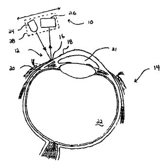
Measurement of Intraocular Pressure Changes
Referring now to Fig. 1, a pressure measuring--
apparatus 10 (partially shown) is brought in close
proximity with a limbus region 12 of an eye 14.
Apparatus 10 is used for measuring contour displacements
which is related to pressure within any physiological
vessel having an elastic or flexible outer membrane which
changes contour in relation to changes in internal
pressure. An eye 14 includes elastic membranes
surrounding aqueous fluid 21 and vitreous fluid 22 which
change internal pressure over a period of minutes, hours,
days, months or years. Pressure readings within eye 14
are preferably taken with reference to regions which
change shape or contour in conjunction with changes in
IOP. Specifically, limbus region 12 includes a fibrous
ring structure region near the annulus 16 bound between
cornea 18 and sclera 20. Changes in IOP of the aqueous
fluid 21 and vitreous fluid 22 cause fluctuations in the
outer contour or shape of cornea 18 and sclera 20
respectively.
Pressure measuring apparatus 10 includes a light
emitter 24 and light detector 26 fixed in space
relationship to each other on a platform 28. It is to be
appreciated that although light is the preferred
reflective medium, other waveforms can be used to project
AME~
2 1 6 ~ 7 9 2 - ~ ~ 4 i ~ 8 ~ 1 2
IPE~IJS O 3 MAR 1995
REPLACEMENTSHEET
t - 20 -
reflected information from limbus~ region 12. For
example, sound waves or acoustical waves may be used to
pr~vide analogous results, i.e., to present waveform
alterations indicating relative positional changes in the
outer contour of the limbus region 12 with the proviso
that the beam displacement relative to the eye be
separately measured to construct the limbus contour.
Platform 28 can be arranged to scan in close proximity to
limbus region 12 in one direction or in both directions,
as indicated in Fig. 1. Movement of platform 28 provides
optical scanning of one or more emitted and reflected
light beams across the entire limbus region.
Alternatively, platform 28 can be stationary and n~rmal
sweep movement (i.e., rotation) of the eye may provide
the necessary scanning of the waves across the limbus
region 12. All that is necessary is that apparatus 10
and limbus region 12 move or scan in relation to each
other, preferably along a single sC~nn;ng axis, defined
as the X-axis as shown in Fig. 2 and described below.
The optical sensor provides a signal related to z axis
displacement to the eye's surface to define the limbus
contour. Note that a plurality of detectors 10 (not
shown) may be arranged to provide a holographic
interferogram three ~;mPnqional real image of the limbus
region 12.
Fig. 2 illustrates the expansion or contraction of
the outer walls in and around limbus region 12 as a
function of pressure. For this example, the
reinforcement at the limbus is idealized as being the
~omin~nt stiffness so that the annul~s rem~in~ relatively
inextensible, and the limbus angle becomes more acute
with increasing pressure. In actuality, due to the fact
that eyes are unique physiological structures, this may,
or may not, be the case. If the reinforcement at the
annulus is relatively soft in comparison to the corneal
and scleral membranes, an increase in pressure will tend
- 2~879~ P~ S9~/08912
O ~ MAR 1995
REPLACEMENTSHEET - 21 -
to take the eye's structure in the direction of becoming
a sphere of uniform radius, or with the limbus, angle
becoming less acute with increasing pressure.
Specifically, rise in aqueous pressure causes cornea 18
to increase from its outer position 18a to 18b.
Likewise, sclera 20 can expand from a low pressure
position 20a to a high pressure position 20b. Because of
the constraint by annulus 16, the point or points of
measurement of angles ~1 and ~2 are relatively fixed on
the eye, and it is one purpose of the present invention
to measure angular changes ~1 and ~2 for the low pressure
contour and high pressure contour positions,
respectively. Several examples of devices and methods by
which the contour shapes can be measured during scan
along the X-axis are described below.
There are various devices which can optically
measure threedimensional contour of an object. One form
of optical contour sensor using light emitting diodes and
photodiodes may be purchased as Model No. HBCS-1100 from
Hewlett Packard, Inc. It is important to note, however,
that an optical contour sensor like the B CS-1100 using
light emitting diodes in conjunction with an aspheric
lens as shown in Fig. 3 generally produces piece-wise
linearity both before and after a set focal point
distance. As will be described later, and illustrated in
Fig. 4, linearity varies depending upon the distance to
the object relative to the point Zmax, where 38
represents the percent reflected photocurrent.
Accordingly, while light emitting diodes used in Model
No. HBCS-1100 are one form by which the present invention
may be practiced, varying other forms having desirable
advantages may also fall within the scope and spirit of
this.invention.
Pressure measuring apparatus 10 illustrating Model
No. HBCS1100 optical sensor 29 is shown in Fig. 3. Sensor
A~hEN~ HEE~
`- 21~8792 P~ S94 / 08 9 12
~t~ 0 3 MAR 1~95
REPLACEMEM SHEET
- 22 -
29 includes a transmission path 30 formed between emitter
24 and detector 26. Sensing occurs by having object, in
this case limbus region 12, placed at a distance along
the Z-axis to obstruct transmission path 30, or complete
path 30 by reflecting the emitter beam to the detector.
In either case, the transmissive or reflective sensing
configuration allows non-intrusive optical readings be
taken corresponding to the intensity and/or position of
the reflected beams.
The characteristics of the transmission path can be
estimated through the use of an optical transfer
function, OTF. The OTF is the ratio of the total optical
flux transmitted to the amount of flux and the ang~larity
(or position) of the beam reflected' back to detector 26.
As will be described below and illustrated in Fig. 4, the
amount of reflected optical flux or light received on
detector 26 is optimum for this embodiment when the
nominal transmission path is set at a specific distance.
As illustrated in Fig. 3, transmission path 30
represents a path'of travel between emitter 24 and
detector 26. The path length is d'ependent upon the
spacing between sensor 29 and limbus region 12 along the
Z-axis. Placed along path 30 is a pair of lenses 32, an
aperture 34 and glass window 36. At least part of
apparatus 10 can therefore be packaged and sold as a
single sensor unit 29, Model No. B CS-1100, of which a
full description is provided-in Optoelectronics
Desiqner's Catalog, Hewlett Packard (1985), pp. 1-39 to
1-44, the disclosure of which is incorporated herein by
reference.
Apparatus 10, which includes an optical reflective
sensor 29, determines the outer contour of r'egion 12 by
- 35 measuring the spacing between apparatus 10 and region 12
as a function of percent reflected photocurrent as
illustrated in Fig. 4. Apparatus 10 can be designed such
îr ij~r~ ~ -
2~687~2
P~IUS94 / 089 12
- ~E~fl)S 0 3 MAR l99S
REPLACEMENTSHEET - 23 -
that an optimal spacing exists between sensor 29 and
limbus 12 such that 100~ reflected photocurrent impinges
upon detector 26 at a particular spacing distance (Zmax)
As apparatus 10 moves relative to region 12 along the X-
axis, the percent reflected photocurrent will eitherincrease or decrease depending upon whether the
transmission path is advancing toward or away from,
respectively, the optimal path length. Zmax is
preferably set at a relatively fixed Z-axis distance
between sensor 29 and the annulus region 16. On either
side of Zmax~ percent reflected photocurrent decreases
from the optimal 100~ as shown in Fig. 4. Zones 39 and
41 are piecewise substantially linear segments tha~
precede and follow the m~Y;~l~m photocurrent point at the
focal point of the aspheric lens. This means that the ~
sensor, in order to avoid duplicate outputs over its
range of operation should be positioned to function
solely in either zone 39 or zone 41 so that the output
slope rem~; nQ monotonic over the range of operation.
Zone 41 has advantages over zone 39 for the present
invention because its range is greater than that of zone
39 (both absolute and usable distance from the limbus is
greater) and the sensor would have greater clearance with
the eye or lashes. Zone 39 has an advantage over zone 41
in that it is of greater sensitivity and linearity, with
a positive slope. The limbus contour signature (and
pressure response contour) will allow accurate estimation
of IOP and BP in spite of the non-linearity regardless of
the zone chosen. The repeatability of the zone used,
however, is important to this application. Lens
characteristics may be modified to tailor the preferred
zone for use.
The sensor reflector distance or trans~ission path
length used in Hewlett Packard Model No. HBCS-1100 is
fairly short and narrow. However, a longer or a broader
range of detectable distances, Z, can be measured
AMEN~ED SHEET
P~T1~94/08912
~6~2
~hlJS `~ 3 MAR 1~95
REPLACEMENTSHEET
- 24 -
embodying the principles of Model No. HBCS-1100. For
example, emitter 24 output can be amplified and different
lenses 32 can be used to refocus the beam so that the
sensor 29 can be placed from 2 millimeters to several
centimeters away from the vessel or region 12. Other
forms of photodetectors can also be used. The most
popular types of photodetectors suitable for use with the
present invention include: Charge coupled devices
(CCD's), PIN photodiodes, lateral-effect photodiodes or
avalanche photodiodes. Detector 26, using a highly
sensitive avalanche photodiode of common design, provides
internal gain to the resulting electrical signal thereby
useable for detecting reflected waves when path le~gths
are relatively long. Photodiodes provide optical-to-
electrical conversion resulting in an analog currentwhich can be manipulated using conventional circuit
techniques. In particular, electrical signals from the
photodetectors can be converted from analog-to-digital
(A/D) format using standard converters such as a
successive approximation A/D converter or -a high speed
A/D flash converter.
EXAMPLE 1
A general embodiment of the present invention iæ
illustrated in the following example. This example uses
the sweep of a beam over the limbus at either approximate
right angle, or tangency, to the limbus to produce the
limbus angle signatures required. In the initial case of
sweep at near right angle to the limbus, the eye may be
~tationary while the beam sweeps relative to the eye. In
the case where the beam sweeps tangent to the limbus, it
is necessary to rotate the eye about a vertical axis so
that the limbus crosses the plane of sweep. This is an
embodiment that will accomplish the same effect as the
subsequent multi-beam unit of EXAMPLE 4, through the
kinematic inversion of sweeping a single beam through an
k '~ 0 ~ ~
2~7~2 F.~.^,., ~4 i G8 9 1 2
IPE~JS O 3 MAR 1995
- 25 -
essentially similar multiplicity of posltion, in lieu of
a multiplicity of beams in fixed positions.
Laser Measurement of Eye Contour
Utilization of a laser for three-dimensional contour
measurement is illustrated in Fig. 5. In particular, a
threedimensional optical measuring technique can be
employed as described in U.S. Patent No. 4,935,635
(herein incorporated by reference). Three-dimensional
contour measurement includes a laser diode 42, polygonal
reflector 44 and photodiode array 46. Further included
is a linear stepper motor 48 having two shafts, on~ shaft
for providing rotation to reflector 44 and the other
shaft for driving a threaded screw cam attached to
moveable platform 28. The laser 42 and photodiode array
46 functions-similar to sensor 29 of Fig. 3 in that
relative spacing along the Z-axis between apparatus 10
and limbus region 12 are sensed to provide a two-
dimensional contour reading. The position of thereturning imaged beam spot along the length of photodiode
array 46 ïndicates the contour or Z-axis distance between
the particular point on region 12 and apparatus 10.
Each measurement of intraocular pressure is achieved
by performing one scan of platform 28 across limbus
region 12. Each scan produces a reflective beam
positional change upon array 46 as the beam travels
across limbus region 12. As the contour changes during
each scan, the angle of incidence changes and the
corresponding reflected wave position upon the array
changes. It is the relative change in the position upon
the array 46 that determines a proportional difference in
depth sensed on the eye surface. This technique of depth
detection to measure threedimensional contour is commonly
described in Patent No. '635 as "triangulation". The y-
AMEND~0 ~flE~
- 2~6~7~2 ~TjVs94/ 08 912
~E~JS O 3 M~R 1-995
R~~MENt SHEET - 26 -
axis dimension is afforded by separate sweeps at
incremental changes in y.
An encoder such as, for example, an analog-to-
digital converter 50 counts each photodiode on a pixel-
by-pixel basis as it is scanned from the photodiode array
46. The resulting counter value representation of
digital data is latched and stored into a local memory
medium 51, whereby it can be later read by a signal
processor 52, illustrated in Fig. 6 and described below.
The choice of local or remote processing of
reflected waveform signals may depend on availabili-ty of
adequate computing power near where the measurements are
generated. In this regard, neural or "neuron" network
electronic chips which are now available may influence
the choice. One such device contains three
microprocessors, several channels of input/output (I/O)
communications and significant on-board random-access and
readonly memory.
Neural chips, in combination with proper on-board
software, are thus capable of converting reflected
waveform signals to estimated IOP and BP changes by
application of values derived from the limbus contour
signature and/or the pressure response contour.
Processing of angle change (reflected waveform) data to
yield estimated IOP and BP in conventional units of
measurement through application of a pressure response
profile is also possible on the chips. Thus, for
example, either physician or patient may obtain an IOP or
BP readout in mm-Hg in nearly real time. The various I/O
options make it possible to provide appropriate warnings
to the patient and even to calculate proper dosage of
3s medication and administer it automatically.
Simultaneously, such chips may process data for storage
in an onboard memory or for direct transmission to a
~ r~ ET
216~7~9~ P~,TjUS94/08912
iPE~JS 0 3 MAR 1995
~EP~CEMENT~HEE~ - 27 -
physician's office via radio telemetry or modem and land
line. Such transmission would ailow prompt
in~erpretation of the data by skilled medical personnel;
impending acute exacerbations of glaucoma or arterial
hypertension may be monitored closely and treated
promptly to avoid or reduce morbidity.
General operation and setpoints for the counter of
analog-to-digital converter 50 and latches within medium
51 are determined based upon which pixel on the array is
currently being interrogated. Other counters may also be
available to determine X-axis position of platform 26 via
stepper motor 48 and X-axis position of platform 26 in
conjunction with polygonal reflector 44 position. Thus,
latched digital data corresponding to electrical signals
placed in memory 51 also provide indicia of the relative
position of the X and Y sC~nn;ng axes via connection to
motor 48.
The light transmitted from laser 42 has a coherent
signature which is sufficiently unique to distinguish it
from ambient light. The angular contour signature of
limbus region 12 is indicated every time the eye rotates
about its vertical axis far enough for the limbus to pass
through the beam. An inclination of the eye about an
axis in the horizontal plane results in deflection of the
beam in a plane normal to the normal scan plane. This
data may be recorded to allow calculation of the eye
position as well as the limbus signature for subsequent
determination of intraocular pressure.
Fig. 6 illustrates a pressure measuring system 60
which includes an apparatus 10 mounted proximate to a
patient. System 60-also includes a remote processor 52
capable of being coupled to apparatus 10. Apparatus 10
is preferably mounted within or proximate to the vessel
region. Specifically, apparatus 10 can be wholly or
A~Ei~ED ~HEET
2~6~7g2 P~TIU~94/08912
- REPLA~MEN~S~EEt ~ 3 MAR 1995
- 28 -
partially mounted within or onto, e.g., the frame of a
pair of eyeglasses 62 placeable upon a patient undergoing
intraocular pressure measurements. Platform 28 can be
secured in moveable relation to a corner 64 of the
eyeglass frame. Platform 28, containing emitter 24 and
detector 26 is moveable between eyeglass lens and eye 14
in close proximity to and over limbus region 12. If a
light-emitting diode similar to that used in Hewlett
Packard Model No. HBCS-1100 is used, the entire packaged
sensor can be mounted on platform 28 and directed toward
limbus region 12 between eye 14 and eyeglass lens 66.
Alternatively, if a laser is used, similar to that shown
in Fig. 5, reflector 44 and array 46 can be mounte~ upon
platform 28 having a motive source provided via cable 68
coupled to motor 48. Laser diode 42 is preferably placed
within a package 70 which houses motor 48, laser diode 42
and a local memory medium 51. A battery (not shown) may
be included within package 70 to supply power for
operation of apparatus 10.
Cable 68 therefore can provide a rotatable
mechanical cable for driving platform 28 as well as an
optical wave guide for transmitting laser energy from
laser 42. Alternatively, if the optical emitter and
detector are fully contained upon platform 28, as shown
in Fig. 8, the electrical signals transmitted to the
emitter and from the detector are contained within an
electrical conductor within cable 68. Thus, depending
upon the configuration desired, i.e., whether a laser or
LED is used or whether the laser is mounted on platform
28 or on pàckage 70, cable 68 may include an electrical
conductor, fiber optic cable, or both. Cable 68 also
preferably includes a rotatable cable which transmits
mechanical rotation from motor 48 to translational
movement of platform 28 and rotational movement of
reflector 44.
~ Q ~fl~T
P~illJS 94 / 08 9 1 2
2~6~7~ pE~03MARl995
~EPLACE~EN~H~ 29 -
Eyeglasses 62 can be of common design generally
adapted to fit in fairly close proximity to the outer
surface or contour of eye 14. Eyeglasses 62, being
fairly stationary in relation to eye 14, provides a
relatively stable and repeatable positioning tool by
which long term and continuous contour measurements can
be taken. Eyeglasses 62 can be worn over a period of
days, months or even years thereby allowing access for
long term intraocular pressure measurements. The
operating distance between the platform movably fixed to
eyeglasses 62 and eye 14 can vary depending upon various
hardware chosen. However, the present design allows
contour measurements at varying operating distance~
anywhere from several millimeters to several centimeters,
or even far beyond as in the case of nonphysiological
applications.
During each measurement routine, platform 28 can be
activated to scan in the X-axis across eye 14 and, in
particular, across limbus region 12. Alternatively, it
is within the scope of the present invention that
sC~nn;ng can be equally achieved by maint~;n;ng platform
28 in a fixed position and naturally moving the eye's
focal point along the X-axis. If platform 28 is movable
to provide the scanning function, eye 12 must remain
fixed in relation to the moveable platform. Thus, the
eye can be focused at a fixed point during each scan
routine so that repeatable measurements can be taken. A
focus point can be provided by attaching a target to
eyeglasses 62, whereby the patient maintains fixed eye
concentration upon the target during each scan routine.
Consequently, each scan presents a scan slice within the
X- and Y-axis. Furthermore, providing eyeglasses 62 do
not slide a substantial distance down the patient's nose,
fixed position along the Z-axis is also maintained
between measurement scans.
AMENDD ~HEET
~6~7~2
- ` ' j4 ~ OB 9 1 2
~PEA~IJS ~ 3 MAR 199~
REPLACEMEN~ ~;HE~
- 30 -
A f~rst set of values representing the limbus
contour slgnature relating alterations in the reflected
wa~eform angle or intensity (electromagnetic or acoustic)
to IOP is stored in a first remote memory medium 54 such
as a floppy disk, compact disk, etc. A second set of
values representing the calibrated pressure response
contour relating alterations in reflected beam intensity
or angle to changes in BP is stored in a second remote
memory medium 56, similar to medium 54. IOP measurements
used in performing the calibration are obtained with a
conventional tonometer applied approximately
simultaneously with an optical scan of the limbus
contour. BP measurements are analogously obtained-with a
conventional sphygmo~-nsmeter. The data obtained during
the optical scan corresponding to IOP and BP readings are
then stored as calibration data within media 54 and 56.
A physician -may induce several pressure changes within a
patient's IOP or BP to establish a broad range of
calibration points.
Signal processor 52 is placed in a remote location
from the patient, preferably in a physician's office.
Processor 52 includes a computer which can receive
downloaded data from local memory medium 51 and compare
that data with data stored in remote memory media 54 and
56. The patient can download data from medium 51 through
a modem connecting the patient's residence to the
physician's office. Alternatively, thè patient may visit
the physician's office and physically connect output via
an RS232, IEEE488, or other port from--medium 51 to
processor 52. Processor 52 may be a personal computer
having external computer bus input and read/write data
capability.
Digital representations of reflected light beam
in~ensities and positions are convertible to changes in
IOP and BP through application of the limbus contour
~.,"it;,l~-c. 3~
2 :~ 6 ~ 7 9 2 P~TI~ 94 / 08 9 1 2
r~ 95-
REPLACEME~ SH~ET
- 31 -
signature and pressure response contour. An example of
the conversion process is represented by the processing
flow chart shown in Fig. 7. During each scan, IOP
measurement data (as stored in medium 51) are entered via
input lines 79 to processors 80 and 83. In processor 80,
BP waveforms are separated by characteristic wave shape
and/or frequency content to be sent on to comparator 82.
Thereafter, IOP waveforms routed to comparator 83 are
compared therein with the stored digital representation
of the limbus contour signature (as stored in medium 54),
while BP waveforms input to comparator 82 are compared
therein with the pressure response contour (as stored in
medium 56) to obtain IOP and BP respectively. Comparison
in each case may comprise a table look-up with
interpolation of previously correlated IOP or BP data as
stored in medium 51 with separate calibrated measurements
of IOP and BP respectively, said measurements being made
at substantially the same time as the correlated IOP and
BP data are taken at the detector (e.g., photodiode array
46). Outputs of comparators 82 and 83 representing
estimated BP and IOP respectively are processed for
display, warning, storage or subsequent digital
processing in processor 84. Thus, as pressure fluctuates
throughout a day, week or year, measurements can be
checked to determine if pressure calculated from each
contour measurement exceeds a pre-determined amount. If
so, the patient is immediately apprised of the situation
so that he or she can administer medication and/or seek
medical treatment. Moreover, processor 52 can provide
direct dosimetry information for medications needed to
achieve more acceptable pressure reA~;n~s. sy monitoring
rapid fluctuations in IOP or BP or long-term trends in
pressure, the present invention provides a more
convenient and accurate monitoring of pressure so that
medication is more effectively dispensed. Timely
intervention can then prevent or delay important
~lEN~ED S~
2~6~732 p~ ,94/08912
3 MAR 1995
REPLACEMENTSH~ET
- 32 -
complications such as blindness (from increased IOP) or
stroke (from increased BP).
A functionally identical scheme was used to evaluate
this concept by the use of a hand-held, Symbol~, laser
bar-code scanner. The output of the scanner was used to
trigger an oscilloscope simultaneously with its beam
sweep. The reflections were recorded on a video-recorder
approximately aligned with the axis of the reflected
beam. Though the sweep of the camera could not be
synchronized with the beam sweep, the pulse at the beam
crossing the limbus could be observed, on the
oscilloscope from the output of the camerals video-jack,
by manually adjusting the sweep vernier to catch the
limbus crossing within the camera's rasterized image. In
this m~nner~ the output change at the limbus could be
measured within approximately one (1) mm of trace
deflection, or to 0.1 V.
A recently slaughtered pig's eye that was
pressurized from approximately 4 to 31 mm-Hg by needle
and syringe as measured by a Schieotz tonometer was
scanned. The pulse generated by the laser beam crossing
the limbus was a sharp peak of less than, a millisecond
duration, but of repeatable character and amplitude. Th
output pulse heights on limbus crossing varied from 0.5 V
at 4 mm Hg, to 1.0 V at 14 mm Hg, and 2.4 V at 31 mm Hg.
EXAMPLE 2
The following example illustrates the apparatus and
method employed in measuring changes in contour and
relating such changes to pressure within the eye. Any
method of measuring limbus contour of sufficient
resolution to define IOP is suitable. This example is
provided from initial efforts to identify existing
sensors to verify the concept. One such device is the
~_ 2~8732 PCTIUS94/08912
bEANS 0 3 MAR l995-
RE4LACEMENTSH~E~
- 33 -
Hewlett-Packard ~BCS 1100, a photoelectric sensor with an
integral light source of specific wave length, or color,
and a detector that measures the light reflected from the
target through an integral lens, designed to optically
couple emitter and detector. This sensor is used to read
digital bar codes, measure thickness of sheet materials,
or detect the presence of a sheet in a feed mechanism,
etc.
Preliminary Measurements on E~e Models and Human Eve
This apparatus was tested initially using a Hewlett-
Packard HBCS-1100 sensor. It was used with precis~on
sweeps past the "limbus" of an acrylic model of a human
eye; and with manual sweeps of the beam past the limbus
of an actual human eye. The data from the output of the
sensor in sweeping the model eye were recorded on one
axis, with the output of a sweep position potentiometer
on the other axis, of an X-Y recorder for three
successive sweeps with slight repositioning of the
initial point between the tests. The results were three
separate traces, displaced slightly, that tracked each
other with nearly perfectly parallel separation. There
was a reversal, or notch, at the instant of crossing the
limbus that was identically repeatable. Under microscopic
evaluation it was determined that there was a scratch in
the plastic at the limbus that gave the notch. This
scratch was visible only under magnification. Subsequent
inspection on an optical comparator, at 40X
magnification, indicated that the scratch was of less
than 1/10,000 (0.0001) inch in depth, yet it produced a
trace deflection on the x-y recorder output of over 1/2
inch. The low intensity LED beam also was passed over
the limbus of the human eye~and the output was
qualitatively observed on an oscilloscope with large
scale deflection. The output was reproducible at the
limbus crossing.
~EN~E~ SffEET
216 ~3 7 ~ 2 r`r ~ 0 8 9 1 2
~P~A/JS O 3 ~AR 1995
REPLACEMENtSHEE~
- 34 -
The HBCS-1100 is not ideal for direct application
due to its short focal distance of less than 0.1 inch
that would require that it be mounted too close to the
eye for practical use. However, the aspheric lens may be
modified to longer focus (Zmax) distance. While this is
generally an expensive and timeconsuming process, a
similar sensor, with integral and sealed emitter/detector
as a single unit, is satisfactory for the described
application. This unit is necessarily fixed in its
- 10 optical relationship and is, therefore, adaptable to
change in prescription for patient's need only by Z axis
placement of the unit or angular alignment of the optical
axis. --
` Fig. 8 is a flow diagram that illustrates a setup,
calibration, and data acquisition scheme for a sensor of
the same type as the HBCS-1100, but with a longer focal
length lens. The integrated assembly of this device
facilitates the installation and adjustment of the unit,
but limits flexibility. It may be desirable to employ a
separate sensor for the measurement of xaxis displacement
as shown in Fig. 3, since the lens somewhat masks the
effect of the discontinuity at the limbus with optical
interference. This probably could be overcome with
additional study of lens characteristics. As shown in
the flow diagram of Fig. 8, the first task is to set the
B CS type sensor in position relative to the eye for
producing the best possible signature from limbus
crossing. The x-axis transducer, which may be a linear
potentiometer, or a DCDT (direct current displacement
transducer, a differential transformer with solid state
oscillator and demodulator, etc.) is also set up to
define that component of the contour profile. The data
unit will include the required signal conditioning for
both sensors along with the power supply for all elements
in addition to that shown in the flow diagram Fig. 9 for
the patient's pocket data acquisition unit (hereinafter
n ~
2~7~2 PC~jVS94/08912
._
~ ~4ql~. .'J ~ iA~' 1995
REPLACEMENTSHEET
- 35 -
the "data unit") function. The flow charts of Figs. 8
and 9 show steps that may be taken to calibrate such a
system for IOP measurement and ready it for data
acquisition in the field. The parts for accomplishing
the items in both of these figures are of common usage in
the field and may be accomplished by numerous
combinations of components by one skilled in the art.
EXAMP~E 3
In order to obtain a system that may be specifically
tailored to a patient's specific requirement~, a system
with greater flexibility is required. Since IOP --
measurement is a function of reflections from essentially
discrete spherical surfaces, beams incident the sclera
near the limbus will give discrete reflections as the eye
rotates so that the limbus crosses the fixed beams.
These beams may be positioned in placement and angle to
produce desired incidence. Additional flexibility for
prescription is afforded by a separate photodetector that
may be positioned independently of the emitter source.
Description of this embodiment is simplified by
considering a single beam source, initially. This is not
overly simplistic since such a system is capable of
making useful measurements, in the physician's office as
well as in patient use and, in fact, is expected to be
the preferred embodiment for most patients. In this
embodiment, as calibration signals are recorded at
several values of IOP, they also are recorded at several
angle~ of elevation of the line of ~ight for each IOP.
AME~D~D 9HEET
-- 2 ~ 6~ 73 2 PGTIus 94 / 08 9 1 2
REPL~CEMENTSHEEr - 36 - ~P~/4U~ 3 3 MAR 1995
S INGLE BEAM EXAMPLE
Fig. 10 shows a system with a single beam in fixed
relation to the eye's socket (center.) The system is
configured by the physician's prescription to meet the
patient's needs; and this figure shows a typical setup.
The lateral axis of the eye in Fig. 10 is horizontal
and in the plane of the paper. The view looking down
this lateral axis is not shown since it is illustrated in
the three view sketches of subsequent discussion in
greater detail. The beam path, and its reflection, lie
in the horizontal plane of the eye's symmetry so th-at
both incident and reflected beams shown in this figure -
are in the plane of the paper. For this idealizedexample, this array would give a straight, horizontal
trace over the surface of an electronic sensor that, in
effect, is the "retinal' of the device (hereinafter
referred to as ER for electronic retina)
View 1 of Fig. 10 shows the eye looking straight
ahead with the beam adjusted to reflect off the sclera
and onto the ER at point "a." The angles labeled 01
represent the angles of incidence and reflection relative
to the surface of the sclera. To acquire data for either
calibration or data acquisition consistent with this
scheme of components, the eye is rotated substantially
about the vertical axis of the sclera. This rotation may
during routine motion of the eye be directed by an image
moving in plane, in front of the eye, or by a maneuver
performed by the patient in rotating his head about a
vertical axis in opposite sense to the desired eye
rotation. The resulting involuntary rotation of the eye
is a motion that is easy to reproduce by both sighted and
blind patients. Since the sclera is nominally spherical,
and the eye rotates about the center of the sclera, there
is little deflection of the beam~ prior to its contact
2~68792 ~ 94/08912
i?~lj~ ~ 3 MAR 199
REPLACEMENTSHEET 37
with the limbus except from the surface roughness of the
sclera.
In View 2 of Fig. 10 the beam has just crossed the
limbus onto the cornea with the result that the beam
angles of incidence and reflection are now at 02. The
extreme deflection of the beam relative to the ER, to
point "b," occurs here. This maximum deflection of the
beam, from a to b, is the analogy for the measurement of
IOP; the axis defining incidence and reflection has
shifted from sclera to cornea.
View 3, Fig. 10 illustrates that beam deflecti-on to
"c," as the eye continues to rotate clockwise is such
that 0, now 03, is diminishing. The increased rate of
beam deflection per unit of eye rotation is due to the
shorter radius of the cornea (relative to that of the
sclera), that governs beam reflection at this
orientation.
In the real case, the limbus is not purely angular,
and the actual step from a to b is "softened" by the
slightly radiused contour of the limbus. The beam path,
recorded by the output from the ER, may be reduced to IOP
units; either directly, from a stored calibration table
or function in the patient's data unit; or indirectly,
where the data is stored on portable medium in the data
unit for subsequent comparison to calibration data in the
physician's office. Medication is authorized according
to prerecorded instructions in the data unit, or by
telephone, modem, pager, etc.
Fig. 11 shows the ER with the points labeled as
described above.
Fig. 12 shows typical output from the sensor, giving
beam displacement relative to rotation of the eye;
~ ENl~D 91~ET
2~ 687~2 -~QJl / ~ 9 1 2
~EPLACEMENTSHEET - 38 ~ 3 3 MAR 1995
The deflection from a to b is related to IOP by the
calibration data. The deflection of the beam in the
vertical plane is a function of the elevation of the
angle of sight, making each image step at the limbus and
its angularity uniquely representative of both limbus
contour and elevation of line of sight.
Fig. 13 shows the effect of approximately 5 of
elevation of the angle of sight on the data. The corneal
outline shown in dashed line in the front view gives
horizontal line of sight; all in solid line is elevated.
The normal to the cornea (its radius since it is
spherical) establishes incidence, and the result is that
the beam is reflected from a to b'. The angle between a
to b' and the axis of the ER (a to b) is proportional to
elevation angle. The signature on the ER, then, consists
of the step from a to b' that is proportional to IOP; and
the angle of a to b, proportional to elevation. The
"softening" of actual limbus contour diminishes the slope
derivative at the limbus and provides a path over the ER
of discrete path and longer duration, making tracking
easier than if it were a true discontinuity. Note that
if the cornea and sclera are truly spherical there is no
need to measure elevation for separate entry for
calibration.
The only difference between calibration data and
that-for actual patient monitor is that, for calibration,
data are taken in the physician's office at several
levels of IOP induced, by medication, and with
~conventional~ tonometry u~ed to mea~ure actual IOP~s
against which beam deflection is compared. This gives
calibration curves of IOPs as functions of peak beam
deflection and angularity. Fig. 14 is a flow chart that
illustrates a setup, calibration, and data acquisition
scheme for systems with discrete beam sources and ERs
that use the défiection at the limbus discontinuity as
216~ 7~2 ~ 94 / 08 9- 1 2
h iP~W~ O 3 ~lAR 1995
REPLACEMENT~H~
the primary transduction principle. Fig. 14 is valid for
both single beam and multiple beam systems with the only
difference being the number of sources aimed at the eye's
surface.
This single beam system was tested by using an
Apollo MP1600 laser pointer through a pin-hole aperture
for beam sharpening; again, with a pig's eye for
analysis. The pressure was from a reservoir connected to
the eye by IV connection, and the pressure equivalent in
mm-Hg was set relative to the pupil, with water column
height. The optical arm from the eye to a sheet of graph
vellum that served as ER was approximately 3.5 in.- In
taking the data, the beam was swept past the limbus by a
vernier on a precision height gage. The angle of
incidence was estimated at 10-150 off normal to the
sclera. The-resulting data are shown below:
SINGLE BEAM DATA2
IOPTrace Deflections - mm
P-mm-Hg
0 36
63
llS
EXAMæLE 4
The single beam method will handle the majority of
patients' needs. Multi, or swept beam devices are
feasible also. One reason for the multi-beam embodiment
is in the case where there is substantial variation of
AMEHD~D ~ET
216~7~2 p~94 / 08 9 1 2
JS O 3 ~i~AR l995
REP~`~cMENTSHE~
- 40 -
limbus contour over the small arc where the contour
signature is to be taken and the definition from a single
source is not discrete-; Another is an increase in the
range of the angle of elevation of the line of sight for
automatically acquired data. These points also are true
for the inversion case where a single beam is swept as in
a bar-code scanner or Example 2 so that it touches or
crosses the limbus with the eye stationary.
1 0 MU1 t i - B eam SY8 t em8
Fig. 15 shows a three-beam configuration that
produces reasonable signatures over a broad range ~f
elevations of line of sight. The principle, illustrated
in Fig. 15 shows progression through three sets of
sketches as the eye rotates so that the limbus crosses
the beam array; the array being fixed in relation to the
eye socket. The top view of View 1, Fig. 15, shows that
the beams for this example are aligned at an angle of
incidence relative to the radius of the sclera so that
the reflections fall on the ER as shown. It is
emphasized that specific geometry and number of beams
will be by prescription of the physician. In this
example, three beams are directed normal to the surface
of the sclera as seen in the view looking directly into
the cornea, with the result that the reflections are at
points al, a2, and a3 on, the ER. These designations
signify:
1. The letters a, b, or c mean that the
reflections are from sclera, the corneal edge
of the limbus, or the cornea surface,
respectively.
2. The numbers 1, 2, and 3 indicate the specific
beam causing reflections shown in the sketches.
~iii~ ~t~T
~T1~ q ~, / 08 9 1 2
J.~ ;" 3 ~Q,R 1995
F~P~ CEMENT ~;HEE~ - 41
view 1 is the initial setup and the reflection
positions remain essentially constant, except for
deflections over blood vessels or other roughness of the
sclera, as the beams move over the substantially
spherical sclera when the eye rotates in its socket. As
the limbus contacts beam 2, as shown in View 2, the point
of reflection on the ER jumps from a2, to b2, as the
spherical surface governing reflection shifts from sclera
to cornea at the limbus. The top view of View 2
illustrates how the angles of incidence/reflection shift
as beam 2 reaches the corneal side of the limbus. Due to
the circularity of the limbus in the front view and the
linear array of beams incident the sclera, beams 1--and 3
are undeflected. The deflection from 'a2 to b2 is the
primary analog for measurement of IOP.
As rotation of the eye continues further in the same
direction, as in View 3, beams 1 and 3 contact the limbus
at al and a3, and are reflected to bl and b3 as shown in
View 3. In this example they are reflected beyond the
surface of the ER, however, the path angles are
preserved, confirming angles of reflections that result
from off-center contact with the limbus. Their symmetry
confirms normal contact between beam 2 and the limbus;
hence "zero" elevation angle. Deflections from al to bl
or a3 to b3 aré, or would be, separate and corroborating
measures of pressure to that of beam 2. (Beam 2 would be
skewed, had there been a change in elevation, and either
bl or b3 would rotate 80 as to move onto the ER.) In
~ 30 View 3, beam 2'8 point of incidence has risen on the
cornea, with the result that it is now reflected to c2.
Beams 1 and 3 may be kept on the ER by geometry
changes in the physician's prescription for the
apparatus. Two examples of prescription change to keep
- the reflections on the ER are offered here: first, the
angles between beams as seen in the front view of View 1,
AME~l~t3 9H~ET
21 6 ~ S 94 / 08 9 1 2
~ 7 ~ ~ lP~ ~3 3 MAP~ 1995
REPLACEMENT SH~E~
- 42 -
which are normal to the surface of the sclera as shown,
may be increased (holding the central beam and points of
incidence fixed) to give an increasing angle of incidence
in this plane, hence, moving the al and a3 positions
closer to a2. Also, the pitch, or spacing between beam
points of incidence, may be reduced by reducing the angle
between them, while keeping them normal to the sclera, to
accomplish the effect of moving al and a3 closer
together. Regardless of details of the setup, the
measured response of the system at various IOPs affords
the calibration.
EXAMPLE 5
15 The prescription for the patient's system may be
determined in the physician's office by a system similar
to those of Figs. 10 or 15, but with adjustability and
verniers or other scales to show adjustment details.
Scans are made after the apparatus has been set to the
physician's satisfaction, to verify the function of the
final configuration of the adjustable system whose
settings are used to define that to be prescribed for the
apparatus to be used in the field.
Calibration
The calibration is accomplished with the patient's
personal apparatus of either separate or integral (to the
eyeglass frame) type, and consists of sweeps,of the eye
past the beam array at several values of IOP over as
broad a range of IOPs as it is practical to induce at the
time of calibration. Separate refers to a system that is
packaged separately from the eyeglass frame which may be
placed over the eye with glasses removed for data
acquisition. This allows for opaque seal to exclude
ambient light from interference with the proper function
~ME~D~D ~ET
2~ ~8 792 P~,it~ ~4 / 08 9 1 2
"~ ~ ~3 ~`IAP~ 1995
REPLACEMENTSHEE~
- 43 -
of the apparatus, but also eliminates automatic
trlggerlng .
The calibration procedure is never complete. Data
from high pressure "events" in the physician~s office
will be recorded, verified by conventional tonometry, and
entered into the calibration data file for calibration
extension at every possible occasion.
A curve, of reasonable range may be generated, in
relatively short order if a high pressure episode can be
used to produce several levels of IOP by quccesæive
medication. Precise measurement of IOP during sca~ for
record is made by a precision unit such as an applanation
tonometer, and scans at several values of elevation may~
be made to establish the correlation between angularities
on the ER, and the values of deflections of the beams
that are proportional to IOP. This method is not
intended to replace precision measure of IOP; rather, it
is a method of detecting high pressure episodes, for
correlation -to the events that cause them. The device
is sufficiently quantitative that medication in proper
dosage may be taken in time to prevent physiological
damage. This invention is sufficiently quantitative to
document diurnal variations, resulting from patient
routine, æo important to treatment of glaucoma. Events
may be cataloged and correlated with other patients with
the same type of glaucoma to aid treatment. It is
difficult to overdose a patient with pressure reducing
drugs, therefore, significant reduction of blindness will
result from this self-monitor method of determini~g
overpressure and proper medication.
IOP measurement by conventional means, with
correlated sweeps are taken at each office visit as part
of the patient's history; and the calibration function is
verified and expanded on a continuous basis. Changes in
2168732 P~ S94/08912
F~ lEN ! ~r L~ pFA~uS O 3 MAR 1995
- 44 -
calibration are extremely important and give advance
notice of physiological change. Excessive IOP, in
addition to causing damage to the optic nerve, also can
cause other permanent change in the eye. This is similar
to the effects of engineering materials being stressed
beyond their proportional limit, with resulting permanent
distortion. This invention offers the ability to detect
and track such damage and to suggest therapy and changes
in patient routine to minimize deterioration.
For final calibration the resulting peak deflections
from limbus crossing are tabulated against induced IOPs'
and the deflection and angular signatures are analyzed
and stored as calibration functions. The values of
induced IOPs are determined by conventional tonometry and
entered into the patient's data unit and/or physician's
computer, manually.
If the head is kept near vertical the rotation of
the eye is restricted substantially to rotations about
the vertical axis. The elevation angle modifies the
angular deflections of the beams that are repeatable
functions of contour, hence are measures of IOP.
Recordings of these signatures at the different induced
pressures and/or elevations produce the calibration
reference.
EXAMP~E 6
The acquisi~ion of data with this unit should be
automatic, if possible, particularly for the case where
the diurnal variation of pressure is desired. This is so
that the pressures will be little effected by having to
think of, and manually prepare for, data capture. If
preparation is required, the patient's response tends to
be influenced by the act of triggering the data. In
general, the data are recorded directly in digital format
~FN~
2 ~ 6 ~ 7 9 ~ s4 ~ ~ 9 1 2
~ Y~A~ 19;95 -
REPLACEMENTS~EET 45
as is consistent with the devices that are typical for
the ER. Several methods of triggering the recording of
data may be used as has been previously illustrated in
Fig. 9.
Data Acquisition
Data from the ER may be monitored on a continuous
basis so that when the triggering event occurs, such as
from the deflection of a beam to indicate IOP beyond a
programmed limit, that data will be recorded in the data
unit. In addition to recording, the unit notifies the
patient by sound or vibration that the data has exeeeded
program limits and that he needs to take appropriate
action. Triggering may be effected by several methods ~
which include, but are not limited to:
A. Continuous monitor, of a "window in time"
(fixed interval), with triggering afforded by
deflection of a beam on the ER in a manner
similar to that for an oscilloscope. The
"width" of the window allows storage of a
precursive time increment (i.e., prior to
triggering) to insure capture of the entire
event.
B. Manual actuation of a switch to "set" the
trigger, followed by head turn to induce
involuntary eye rotation; this is useful in
recording events where the patient notices
something that indicates he ~hould record his
IOP. Automatic disablement of this feature
generally will be programmed to prevent
interference with a previously tri~gered event,
being recorded, that the patient is not aware
of, though a "recording" light will be included
on the data unit to indicate that recording is
2 ~ 7 ~ 2 ~~ 4 / 08 9 1 2
- ~ lPt~VS O 3 NIAR 1995`
R~LACEMENTSHEE~ - 46 -
in progress. This disablement also may be set
to vary ~window width," ~o restrict recording
time and conserve memory.
C. Data may be triggered by combinations of
programmed timing in the data unit to arm the
trigger to record the next limbus crossing as
sensed by the discontinuous step on the ER, or
by notifying the patient by something, such as
a vibrator that it is time to manually record
data. Automatic triggering is helpful in
establishing diurnal pressure variations for
the patient. Data may include date and t-ime as
part of the format.. "Peak memory" update may
be used to capture and store extremes of
pressure excursion triggered by routine eye
motion that surpasses previously recorded
deflection.
D. The simplicity of data format required to store
IOP defining information (beam deflection and
angle) makes feasible the continuous
acquisition of data for 24 hours or more.
The beam sources should be as independent of ambient
spectra as possibIe to m; n; m; ze background interference
for the integral unit. This is inherent in the separate
apparatus since background i8 eliminated. While it is
desirable to maintain a cosmetically pleasing
configuration for the integral unit, it may be that a
sealed or shaded "goggle'' mu~t be adopted to control
ambient interference. It is possible to sample ambient
spectrum as part of each data set and apply appropriate
correction, but this complicates collection, reduction
and correction of the data significantly. Each beam may
be given a different character (such as color) for
AMEND~DSHEET
216~7g2 P~ s4 / .Oap~s l2
REPL~CEMENT SHEE~
identification. The separate unit has no background
clutter, of course.
EXAMPLE 7
For the integral system, the data unit may be kept
"at the ready" continuously, or "armed" by a separate
timing function, and triggered by signal characteristics
and conditions that may be either external to, or
continuously monitored on, the ER itself. In this way
the diurnal variation of IOP during the patient's routine
may be determined for his treatment in a manner that is
impossible under monitor by conventional tonometers-.
Data Storage, Reduction and Processinq
Once triggered, analog or digital data from the ER
is recorded by the data unit to store the paths of beam
reflections as the beam crosses the limbus. An example
here is data from pixel by pixel illumination as a beam
travels over a charge coupled device (CCD). The
signature of a limbus arc segment may be constructed from
the signatures of multiple beams to characterize
asymmetric corneal distortions in conjunction with three
dimensional mapping, drawing, or solid modeling software
to identify physical anomalies. Asymmetry may result if
the cornea or sclera are stretched beyond their elastic
limits. The single beam unit is expected to be
sufficient for IOP measurement, in most instances.
Notice that there is no real "zero" since there is always
a finite limbus angle. Analytical comparison techniques
such as from Fourier or other geometric analysis may be
used to extract secondary information from the signatures
that may be of value comparable to that of IOP itself,
particularly with regard to similarity of response
between patients with the same type of glaucoma.
~r~ ~
2168797 ~p~ M2R1995
- ~IJACEME M ~HEET
- - 48 -
The data unit is as compact as possible, and
provides dependable capture of IOP related contour
signatures. The data unit contains an EPROM, programmed
in accordance with prescription from the physician, to
control the storage of data from the ER in RAM. Data is
recorded on storage media such as magnetic tape or cards
and may be communicated from the patient to the
physician's office for analysis. This allows the
physician to be involved in the diagnosis and treatment
of the patient, to a degree and in a time frame,
previously impossible for treatment of glaucoma. The
ability to know IOP in nearly real time will be very
effective in preventing physiological damage that aan
cause bl;n~ne~s. Fig. 16 is a flowchart example of data
acquisition, reduction, analysis, and handling for the
field monitor of IOP or BP.
Since the eyelids are of relatively constant
thickness, thereby modifying limbus contour in relatively
constant fashion, the possibility of making measurements
with eyes closed is feasible, though reflective ointment
on the eyelids would be necessary to insure reasonable
reflection. This concept is to be evaluated as
development of this invention continues. The capability
of measuring IOP through the eyelid would be very
effective in making automatic measurements of IOP during
sleep, when the body's supine position increases the
systolic blood pressure component of IOP due to the
increase in the heart's height relative to the eye. In
many instances the most damaging events to the eye, from
glaucoma, occur during sleep.
EXAMPLE 8
35Similar apparatus and procedures may be used to
measure blood pressure, blood chemistry, and pulse rate.
The pupils of the eyes are the only transparent windows
AM~ ~D ~HEET
P~,T~ 4 / 08 912
2 ~ 6 8 7 ~ 3 MAR 1~5
REP~ ''F~T SHEET
-- 49
in the body where blood vessels and nerves may be
observed without an opaque barrier to their translucent
walls. Blood vessels are visible on the surface of the
sclera, with a clarity unequaled elsewhere on the body.
The opportunity to view these vessels and nerves provides
a unique opportunity to use signature analysis techniques
to "learn" the nuances of physical shape and color in
relationship to health or disorder. The measurement of
blood pressure may be deduced from the distortions of
blood vessels on the surface of sclera or retina in a
manner similar to that described for measuring IOP, i.e.,
through signature analysis of the reflections from the
vessels, in direct comparison to calibration signatures
recorded in the physician's office.
Physiological condition related to the color of
vessels and nerves are visible in or on the eye. The
color of these elements may be quantified by spectrum
analysis, where the colors of specific elements may be
discretely analyzed to identify and quantify their
presence. As an example, the color of the optic nerve is
directly related to its health; a healthy nerve being
bright orange or pink; fading to a dull gray as it
deteriorates or dies.
Blood Pressure and Optic Nerve
Similar apparatus to that described for the IOP may
be used to measure carotid artery distortions (i.e.,
changes in the artery's physical size/shape from blood
pressure according to the equations of mechAn;cs). The
apparatus for making these measurements is not intended
for continuous monitor, but to offer enhanced diagnostics
of the patient's general health from scans of the eye
during routine physician's office visits. Positioning
hardware to accurately locate the apparatus for such
applications may be used to make complex, yet precise,
r
,~ g,1~ P~a~94 / 08 9 1 2
IPE~VUS 3 3 MAR lq9.
R~P~E~ENtSHEE~ 2 ~ 6 ~ 7 ~ ~
physiological measurements in both clinical and non-
clinical settings.
The images of the carotid arteries are irregular and
are not suitable for analysis by the simple beam
deflection afforded by the limbus discontinuity for
deducing IOP. The mapping of blood vessels and the
reflections from them that are indicative of both
systolic and diastolic blood pressure components requires
that a two ~;m~n~ional image be constructed to identify
specific vessels chosen for data and ta record the
complex reflections from them. This implies that a
rasterized scan of the ER be employed (which then gives,
in essence, a video camera). The output from this
"camera" may be taken to a "correlator" to analyze the
similarity between the calibration recordings taken in
the physician's office, and the patient's field data, in
the time domain (crosscorrelation) ; the result being a
measure of similarity between the signals.
Alternatively, the signals from the full ER matrix may be
compared, digitally, to determine their similarities.
Such similarities are qualitatively related to each
other, and may be quantified by comparison to the IOP
measured separately on calibration. Further, images from
the carotid artery may be compared with images of itself
taken at different times ~autocorrelation) to quantify
change in patient condition. There are numerous other
methods of comparing data sets; these are chosen for
example, but are not the only means of comparison.
Determination of ~lood pressure also may be made
from similar analysis of the surface blood vessels on the
sclera; however, these vessels are smaller, therefore
less likely to give the resolution afforded from the
carotid. In order to get a good image of the carotid,
through the pupil, it is necessary to get close enough to
get a full view of the retinal plane. This problem may
A~EN~ED SHEEr
2 ~ 687~ PFT/US94/ 08 912
rAI~ v 3 lilAR 199~ -
~EPLACEMEN~SHEET
- 51 -
be alleviated by using a wavelength of light that is not
in the visible range, allowing the pupil to remain in
rel~tively dilated condition.
Dynamically varying signals such as those from
pulsations of blood vessels due to diastolic variation
may be analyzed by Fast Fourier Transform (FFT) methods
in a "spectrum analyzer" that processes signals in the
frequency domain to quantify harmonic content. In this
instance, spectrum refers to the dynamic,as opposed to
color spectrum. Data from the ER, directly, or from the
correlator above, may be edited into "endless loops," or
repetitively played from digital storage, for anal~sis in
the frequency domain. Since correlation functions of
periodic functions also are periodic, at the same
frequency, correlation functions may be FFT processed in
the frequency domain (cross power spectral density) to
sharpen the desired dynamic components such as from
diastolic blood pressure variation. The diastolic
components also may be isolated by digital comparison of
images from successive raster scans from the ER, with the
extreme variations defining the sum and difference of
systolic and diastolic comro~ents, respectively, all of
which are related to the calibration images taken at
known pressures.
The color spectrum of reflections from the nearly
transparent walled carotid artery may provide discretely
identifiable signatures related to blood sugar, oxygen,
alcohol levels, etc., to allow virtually instantaneous
blood chemistry analysis. The spectrum of the optic
nerve is qualitatively related to its health, with a
healthy nerve being a bright red orange or pink, fading
to a dull gray as the nerve deteriorates or dies. Color
spectrum signature analysis according to modern methods
such as from imaging spectrographs (Purcell, 1993)
provides powerful diagnostics for general patient
~ t_!~'jt~ ~F~
2 ~ 6 ~ 7 9 2 PcTl~s 94 / o8 9 l 2
IPEA/US O 3 MAR 1995
5~NT ~H~E~ - 52 -
monitoring. Comparisons between spectra of patients withthe similar disorders may provide direct diagnosis of
numerous disorders.
In summary, the eye is the only transparent window
in the body where direct observation of critical blood
vessels and nerves, that respond to numerous disorders,
is afforded. Response to these disorders may be
characterized by observing signatures from the vessels or
nerves themselves and comparing them to related
physiological functions that are measured, independently,
by conventional methods at the same time. Correlations
between these phenomena allow recording of images ln non-
clinical settings from which deductions of the related
functions are obtained in short time frame.
EXAMP~E 9
The reduction of data for IOP is relatively simple
and consists of comparing data defining the limbus
contour against the calibration standards for that eye
where data are taken under controlled clinical conditions
with separately measured pressure and angles of
elevation. Data processing includes determination of the
deflection and angle relative to the ER and interpolation
to give IOP.
Blood pressure, or BP, processing is more difficult
and requires that the image of the vessel, chosen to
determine the pressure related signatures, be corrected
for position and orientation before the comparison is
made. This implies that a reference point, and angular
reference must be used to bring both calibration and data
sets into physical register with each other.
Magnification may be reasonably stabilized by precision
placement of the scanning unit (as may the angular
orientation) which is connected to the patient's data
~J~El~DED 9H~T
2~687~ PCTIUS94/ 08912
i 3 MA~ 1395
- ~EPLACEMEN~SH~ - 53 -
unit in either case. A separate unit seems superior to
any continuously worn, or "integral" apparatus, since
special provisions for precision placement, and exclusion
of ambient interference would be better afforded.
Data Processing
As mentioned in the introduction above,
determination of IOP is a relatively simple process
involving the comparison of the peak deflection of a data
beam, as recorded in the patient's data unit to the beam
deflections that occurred with the same apparatus during
calibration in the physician's office. This requirês
little beyond applying linear interpolation between, or-
extrapolation beyond, the calibration curve IOPincrements, induced in the physician's office, to the
measured peak beam deflections observed in the data. The
angular path over the ER during beam deflection gives the
elevation of the eye. The IOP is determined by double
interpolation between angle and peak beam deflection to
give the IOP. Since the devices for an ER are of the
digital matrix type, or an analog type that may be
converted to digital format, pixels defining rows and
columns, sensitive to light give the instantaneous
position of the reflected beam. If data is recorded for
a window in time, the excursion of the beam over the ER
is faithfully recorded. The "jump" at the discontinuity
gives both limbus angle and azimuth related to the angle
of elevation. Such data may be processed and compared
with the calibration references in a fraction of a second
for virtually real time indication of IOP.
Data reduction for BP measurement is more
complicated. The image of the carotid artery is complex,
with little or no correlation between patients; nor is
there any symmetry or discrete geometric discontinuity as
with the external surface of the eye at the limbus. The
~t ~
- 2 :~ 6 8 7 9 2 IP~ o 3 MAR 1992
REPLACEMENT SHEET
-- 54 --
task is to relate the two-dimensional images, of the
carotid or scleral vessels on the ER, to BP. This
requires that separate images of the carotid from the ER
be compared, with the difference between them being the
signature to be related to pressure. In this instance,
it is first necessary to correct for positional
differences of images on the ER. Some major feature is
chosen as "Zero" reference and the images are "correctedl'
to the same reference.
It is expected that position and magnification may
be sufficiently maintained to preserve scale reference
for the image. The reference should be as discret-e a
point as may be identified, for the specific patient, and
the alignment or rotational orientation of the image be
positively identified either by physical registry of the
apparatus or-by a second image comparison. There are
numerous geometric analysis programs that may be used to
process the data from the pixels to identify these
features. This allows correction of the images to a
common origin, angular orientation, and scale.
Differences between subsequent image matrices, for
determination of systolic pressure and diastolic
variation, compared with the references taken for
calibration, give the signatures that may be used to
measure BP. Several comparisons must be made to
establish both systolic and diastolic components of blood
pressure to insure that both high and low peaks of
distortion from diastolic pressure are obtained. The
determination of BP requires some process time, but may
be quicker than that for conventional sphygmomanometer
and at a fraction of the size and weight. In this
instance, the data unit will be larger than that for IOP
due to the greater requirement for full, multiple, image
processing and differencing. Current "palm-top"
computers have adequate storage and processing
capability. The "separate" package for the sensors and
~iAE~DED 91~EET
2~G37~2 PCTIllS94/08912
3 ~.lAR 1~95 -
~ i S~ t --55--
ER array may be of the size of a pack of cigarettés or
so. These package sizes may be expected to shrink with
the trend in instrument development to smaller packages.
Alternatively, the unit may be configured to store the
corrected images in a simple, and physically smaller,
memory for subsequent transmission to the physician's
office for processing. Sequential images at high storage
rates may be used to reconstruct the dynamic character of
BP including "murmurs" or other anomalies.
Complex color spectral data may be recorded
(Purcell, 1993). These data are not expected to be
highly dynamic; however, data will be evaluated at ~
sufficient data rates to determine if high rate changes
in color spectra occur during strenuous or stressful
æituations. The use of spectrographic imaging may be
used to isolate specific dynamic temperature variations
from color photothermography (colors proportional to
temperature). While there might be some value in
ambulatory monitor of color spectra, this is expected to
be primarily a clinical unit used for checks during
routine office visits, etc. A special CCD color spectral
processor could be made pocket size; again, with a
separate recording media for storing the images.
* * * ,* * *
k.lsr KKL_J_ KS
Purcell, Frank ln Laser Focus World, "Imaging
Spectrographs Performed Multidimensional Spectroscopy,"
May 1993, pp. 93-97
.