Note: Descriptions are shown in the official language in which they were submitted.
21~816
IMPROVED COUNTERSHAFT POWER TRANSMISSION
Technical Field
The invention relates generally to countershaft
transmissions, and more particularly to countershaft
transmissions having a large number of speeds suitable for use
in work vehicles such as agricultural tractors and industrial
equipment. The invention further relates to methods of
providing such speeds.
Backqround Art
For efficient performance of a wide variety of tasks,
work vehicles such as agricultural tractors and industrial
equipment have a large number of speeds. Usually, the
operators of these vehicles prefer to have a large share of
the forward speeds in the regular working zone of
approximately five to fifteen kilometers per hour.
Often, these work vehicles use countershaft transmissions
having numerous rotating components such as shafts, gears,
clutches, and bearings. In the typical countershaft
tran~mission, the power train includes a speed section
connected to a range section. Commonly, the speed section
precedes the range section and receives input power from the
engine. The range section is used to select a range or series
of operating speeds for the output power. For each selected
setting of the range section, the speed section functions to
~5 select any one of the series of speeds.
There are many ways to improve the countershaft
transmissions. By decreasing the change in energy level of
the rotating components during a shift between different
ranges, one can decrease the time required for the particular
shift as well as increase the smoothness of the shift.
Furthermore, by decreasing the number of components, one can
decrease the amount of material required for assembling the
transmission. Moreover, by increasing the compactness of the
countershaft transmission, one can decrease the space required
in the work vehicle for the transmission, thereby increasing
the flexibility of fitting the transmission into the vehicle.
Currently, Funk Manufacturing Company produces and sells
a countershaft transmission for agricultural tractors having
eighteen forward speeds and nine reverse speeds. Seven of the
~16881 6
.
.
forward speeds are included in the regular working zone. The
transmission uses twenty-two gears and nine clutche~ arranged
euch that 8iX clutches form the speed section and three
clutches form the range section. Furthermore, one of the
clutches is dedicated to providing a range containing
exclusively the reverse speeds. Also, the shafts are
staggered lengthwise with respect to each other such that they
are supported for rotation by three walls that are assembled
together to form the housing. The transmission is arranged so
each gear ratio sequence is used exclusively either for
decreasing, transmitting identical speed as, or increasing
speed transmitted to the gear ratio sequence. A first range
includes nine forward speeds. A second range includes nine
forward speeds consecutive to the speeds of the first range.
A third range includes nine reverse speeds. Therefore, a
range shift between the forward speeds requires making the
complete change in energy level between the different ranges.
U.S. Patent No. 5,063,793 discloses a countershaft
transmission having twenty-four forward speeds and twelve
reverse speeds. Excluding an optional power takeoff, the
preferred embodiment of the transmission uses twenty-five
gears and ten clutches arranged such that six clutches form
the speed section and four clutches form the range section.
The six clutches of the speed section are each arranged to
provide six forward speeds and three rever~e speeds, so no
range iB dedicated to providing exclusively reverse speed~.
Also, the shafts are staggered lengthwise with respect to each
other. The transmission is arranged so each gear ratio
sequence is used exclusively either for decreasing,
transmitting identical speed as, or increasing speed
transmitted to the gear ratio sequence. Each of the four
ranges includes consecutive groups of six forward speeds and
three reverse speeds. Therefore, a range shift requires
making the complete change in energy level between the
different ranges.
Even with the improvements that have been made in the
countershaft transmissions of work vehicles such as
~16S816
agricultural tractors and industrial equipment, it iæ still
desirable to provide further decreases in the change in energy
level of the rotating components during a shift between
different ranges, decreases in the number of components in the
transmission, and increases in the compactness of the
transmission.
Summary of Invention
One object of the invention is to decrease the change in
energy level of the rotating components during a shift between
the different ranges in a transmission having a large number
of speeds.
Another object is to decrease the number of rotating
components in a transmission having a large number of speeds.
A further object of the invention is to increase the
compactness of a transmission having a large number of speeds.
Still another object of the present invention is to
provide a large share of forward speeds in the regular working
zone while increasing the compactness of a transmission.
According to the present invention, the foregoing and
other objects and advantages are attained by a transmission
including an input shaft, a plurality of countershafts, and an
output shaft rotatably mounted in a housing. The input shaft
has an input end for receiving input. An input gear is fixed
to the input shaft. The output shaft has an output end for
providing output. A fixed gear is fixed to the output shaft
and each of the countershafts. At least one rotatable gear is
rotatably mounted on the output shaft and each of the
countershafts. Each rotatable gear is selectively fixed to
its shaft by a respective clutch. A plurality of the
rotatable gear8 form an input set that is meshed with the
input gear. Any selected rotatable gear of the input set can
be fixed to its shaft and drivingly connected to any selected
one of a set of gear ratio combinationæ that are formed using
a plurality of the gears in order to provide speeds at the
output end of the output shaft for the output. A gear ratio
sequence, formed by drivingly connecting a plurality of the
gears, provides a decrease in speed for at least one of the
2~6881 ~
gear ratio combinations and an increaæe in speed for at least
one other of the gear ratio combinations.
In accordance with an aspect of the invention, a
transmission has a speed section and a range section. A
plurality of countershafts are designated as speed
countershafts to form the speed section. First and second
range countershafts and an output shaft form the range
section. Through an arrangement of the speed section, any
selected rotatable gear of an input set can be fixed to its
shaft and drivingly connected to any selected one of a set of
gear ratio speed combinations that are formed using a
plurality of gears of the speed section in order to provide
speed section results. Through an arrangement of the range
section, the speed section results are drivingly connected to
any selected one of a set of gear ratio range combinations
that are formed using a plurality of gears of the range
section in order to provide speeds at an output end of the
output shaft for output. A middle range of speeds for the
output includes at least one speed that is lower than at least
one of a low range of speeds for the output and at least one
other speed that is higher than at least one of a high range
of speeds for the output.
In accordance with another aspect of the invention, a
method of providing a plurality of speeds drivingly connects a
plurality of gears to form a gear ratio sequence that is
included in at least one gear ratio combination in order to
provide a decrease in speed transmitted thereto and in at
least one other gear ratio combination in order to provide an
increase in speed transmitted thereto.
In accordance with a further aspect of the invention, a
method of providing a plurality of speeds staggers at least
one of a middle range of speeds with at least one of a low
range of speeds and at least one other of the middle range of
speeds with at least one of a high range of speeds.
Additional objects, advantages, and novel features of the
invention will become apparent to those skilled in the art
upon exAminAtion of the following detailed description of the
216~
preferred embodiments of the invention when read in
conjunction with the accompanying drawings.
Brief Description of the Drawings
FIG. 1 i8 a schematic illustration showing the
interrelationship between FIGS. 2A and 2B.
FIG. 2, comprising FIGS. 2A and 2B, is a sectional side
map view showing a transmission constructed according to the
present invention.
FIGS. 3 through 7 are fragmentary representations
oriented along lines 3-3 through 7-7, respectively, of FIG. 2.
Detailed Descri~tion of the Preferred Embodiments
of the Invention
In the description below, the reader is assumed to
understand the FIG. 1 illustration of the interrelationship
between FIGS. 2A~and 2B, which comprise FIG. 2.
For clarity in the description below, references for
shafts begin with the reference letter S and conclude with a
reference numeral. Each of the references for fixed gears,
that is, gears integrally formed with or otherwise fixed to
their shafts, begins with the reference letters GF and
concludes with the reference numeral of its corresponding
shaft. For example, fixed gear GF1 would be fixed to shaft
S1. References for rotatable gears, that is, gears that
optionally can either rotate on their shafts or else be fixed
to their shafts by their corresponding clutches, begin with
the reference letters GR. Each of the references for the
clutches begins with the reference letter C and concludes with
either a reference numeral or letter. In order to indicate
the interrelationship between the rotatable gears and their
corresponding clutches, the remainder of each of the
references for the rotatable gears includes the concluding
reference numeral or letter of its corresponding clutch. For
example, rotatable gear GR1 would correspond to clutch C1 and
rotatable gear GRA would correspond to clutch CA. Each of the
references for multiple rotatable gears corresponding to the
same clutch concludes with a sequential reference letter. For
216~816
example, rotatable gears GRBA and GRBB would correspond to
clutch CB.
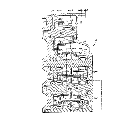
FIG. 2 shows a transmission 10 including a housing 11
that supports a plurality of rotatable shafts, gears,
clutches, and bearings. The shafts are aligned parallel with
one another and supported for rotation by two walls 12, 13
that are assembled together to form the housing 11.
Input shaft Sl is rotatably mounted in the housing 11 and
has an input end 14 for receiving input power. A fixed input
gear GF1 is fixed to the input shaft S1. In the preferred
embodiment, the fixed input gear GF1 is formed integrally with
the input shaft S1. Furthermore, the input shaft S1
preferably has a takeoff end 16 for providing takeoff power
that can be used in known ways to power various implements or
accessories which are commonly utilized in conjunction with
work vehicles such as tractors.
Rotatably mounted in the housing 11 are countershafts S2,
S3, S4, S5, output shaft S6, and countershaft S7. Fixed gears
GF2, GF3, GF4, GF5, GF6, GF7 are fixed, such as by welding, to
their corresponding shafts S2, S3, S4, S5, S6, S7. Rotatable
gears GR1, GR2, GRR, GRA are rotatably mounted on and
selectively fixed to their corresponding shafts S4, S2, S3, S2
by respective clutches C1, C2, CR, CA. Rotatable gears GRBA,
GRBB are rotatably mounted on and selectively fixed to their
shaft S3 by clutch CB. Preferably, the rotatable gears GRBA,
GRBB are formed as a double gear, as shown in FIG. 2.
Rotatable gears GRC, GRL, GRM, GRH are rotatably mounted on
and selectively fixed to their corresponding shafts S4, S5,
S7, S6 by respective clutches CC, CL, CM, CH. The output
shaft S6 has an output end 18 for providing output power.
As shown in FIGS. 3 through 7, the input shaft S1 is
positioned somewhat centrally in a roundish arrangement of the
countershafts S2, S3, S4, S5, the output shaft S6, and the
countershaft S7, listed in the order of their counterclockwise
appearance in the arrangement starting with the countershaft
S2. As shown in FIGS. 2 through 4, the input gear GF1 is
216~816
meshed with the rotatable gears GRl, GR2, GRR that form an
input set of the rotatable gears.
As can be determined from FIGS. 2, 3, and 4, the clutches
Cl, C2, CR can selectively fix one of the input set of the
rotatable gears GRl, GR2, GRR to its corresponding shaft S4,
S2, S3, respectively, in order to receive from the input gear
GFl speed derived from the input power and transmit a result
of this speed to selected gear ratio combinations of the gears
GF2, GF3, GF4, GF5, GF6, GF7, GRA, GRBA, GRBB, GRC, GRL, GRM,
GRH in order to provide any selected one of a number of speeds
at the output end 18 of the output shaft S6 for the output
power. The gear ratio combinations are distinct because of
the gears actually being drivingly connected.
The gears are drivingly connected to form the gear ratio
combinations. Such driving connection can involve direct
meshing of the gears fixed to their shafts or else rotatably
mounted on their shafts, with or without activation of one or
more of their respective clutches. Additionally, the driving
connection can involve one or more of the gears fixed to the
same shaft or rotatably mounted on the same shaft, with
activation of their respective clutches.
The transmission 10 is arranged in a speed section and a
range section. The shafts S2, S3, S4, the gears GF2, GF3,
GF4, GRl, GR2, GRR, GRA, GRBA, GRBB, GRC, and the clutches Cl,
C2, CR, CA, CB, CC form the speed section. The shafts S5, S6,
S7, the gears GF5, GF6, GF7, GRL, GRM, GRH, and the clutches
CL, CM, CH form the range section.
The speed section receives the speed derived from the
input power by using the clutches Cl, C2, CR to selectively
fix one of their respective rotatable gears GRl, GR2, GRR of
the input set to its corresponding one of the shafts S4, S2,
S3, as can be determined from FIGS. 2, 3, and 4. Whenever one
of the clutches Cl, C2, CR is activated in order to receive
the speed derived from the input power, then one of the
clutches CA, CB, CC is also activated in order to transmit a
selected one of a set of speed section results of the speed
derived from the input power to the range section at one of
2168816
the gears GRA, GRC through a selected one of a set of gear
ratio speed combinations that are formed using the gears GF2,
GF3, GF4, GR1, GR2, GRR, GRA, GRBA, GRBB, GRC of the speed
section, as can be determined from FIGS. 2, 6, and 7.
The range section receives the speed section results of
the speed derived from the input power by using the one of the
rotatable gears GRA, GRC to drive a selected gear ratio range
combination of the gears GF5, GF6, GF7, GRL, GRM, GRH of the
range section in order to provide the output power. In the
preferred embodiment, activation of the clutch CL selects a
low range of speeds for the output power so the gear GF5,
drivingly connected to the gear GRL, receives the speed
section result from the gear GRC of the speed section, as
shown in FIGS. 2, 5, and 7. Further, activation of one of the
clutches CM, CH selects a corresponding middle or high range
of speeds for the output power so the gear GF7, drivingly
connected to the fixed one of the gears GRM, GRH, receives the
speed section result from the gear GRA of the speed section,
as shown in FIGS. 2, 5, and 6.
The low range of speeds, selected by activating the
clutch CL, includes the lowest of the speeds for the output
power. The high range of speeds, selected by activating the
clutch CH, includes the highest of the speeds for the output
power. The middle range of speeds, selected by activating the
clutch CM, overlaps the low and high ranges of speeds. In
particular, the middle range of speeds includes at least one
of the speeds for the output power that is lower than at least
one of the speeds of the low range of speeds and at least one
other of the speeds for the output power that is higher than
at least one of the speeds of the high range of speeds. As
discussed below, this overlapping of the middle range of
speeds with the low and high ranges of speeds provides the
operator of the work vehicle with a large share of the speeds
in the regular working zone. Furthermore, the operator can
shift between successive speeds that appear in the different
ranges of speeds without making the complete change in energy
level between the different ranges.
216~81 6
.
The gear ratio combinations of the gears of the speed and
range sections depend upon the preselected meshing of the
gears, the selective activation of the clutches, and the
preselected tooth count for each of the gears. As shown in
FIGS. 2 through 4, the input gear GF1 is meshed with the
rotatable gears GR1, GR2, GRR of the input set. As shown in
FIGS. 2 and 5, the fixed gear GF3 is meshed with the fixed
gear~ GF2, GF4. Formed as the double gear shown in FIGS. 2,
6, and 7, the rotatable gears GRBA, GRBB together are
rotatably mounted on the shaft S3 and selectively fixed to the
shaft S3 by activation of the clutch CB. As shown in FIGS. 2
and 6, the rotatable gear GRA is meshed with the rotatable
gear GRBB and the fixed gear GF7, which in turn is meshed with
the rotatable gear GRH. As shown in FIGS. 2 and 7, the
rotatable gear G~C is meshed with the rotatable gear GRBA and
the fixed gear GF5. As shown in FIGS. 2 and 5, the fixed gear
GF6 is meshed with the rotatable gears GRL, GRM. The gear
ratio obtained by meshing any pair of the gears GF1, GF2, GF3,
GF4, GF5, GF6, GF7, GR1, GR2, GRR, GRA, GRBA, GRBB, GRC, GRL,
GRM, GRH is a function of the corresponding tooth counts. In
the preferred embodiment, the gears shown in FIG. 2 have the
tooth counts indicated below in Table 1.
TABLE 1
Tooth Tooth Tooth
25Gear Count Gear Count Gear Count
GF1 32 GF7 65 GRBB 70
GF2 71 GR1 62 GRC 70
GF3 71 GR2 48 GRL 40
GF4 71 GRR 62 GRM 40
GF5 74 GRA 42 GRH 48
GF6 72 GRBA 42
As will be well understood by those skilled in the art,
one can obtain the desired speed for the output by selectively
2168816
combining the gear ratios of drivingly connected pairs of the
gears GF1, GF2, GF3, GF4, GF5, GF6, GF7, GR1, GR2, GRR, GRA,
GRBA, GRBB, GRC, GRL, GRM, GRH. Further, the gear ratios of
the drivingly connected gears and the position of the double
gear formed using the gears GRBA, GRBB are depicted according
to design considerations reflecting the speeds preferred by
the manufacturer, seller, purchaser, and operator of the work
vehicle.
In the preferred embodiment, the clutches Cl, C2, CR, CA,
CB, CC, C~, CM, CH are selectively activated as indicated
below in Table 2 to fix their respective gears to their
corresponding shafts in order to receive the speed derived
from the input power and provide the output power. Those
skilled in the art will understand the values indicated in
Table 2 for approximate kilometers per hour (approx. k.p.h.)
help describe the present invention, but are only
representative and will vary depending upon wheel size, axle
ratio, and other characteristics of the work vehicle.
- 10
216~81 6
,
..
TABLE 2
Range Clutches Activated
p L M H Cl C2 CR CA CB CC CL CM CH G A
e o i l Ratio k.p.h.
e w d g
d d h
e
Fl L Cl CA CL -10.241 2.4
F2 L C2 CA CL -7.929 3.1
F3 L Cl CB CL -6.145 4.0
10 F4 M Cl CA CM -5.397 4.6
F5 L C2 CB CL -4.757 5.2
F6 M C2 CA CM -4.179 5.9
F7 L Cl CC CL -3.687 6.7
F8 M Cl CB CM -3.238 7.6
15 F9 L C2 CC CL -2.854 8.7
F10 M C2 CB CM -2.507 9.8
Fll H Cl CA CH-2.214 11.1
F12 M Cl CC CM -1.943 12.7
F13 H C2 CA CH-1.714 14.4
20 F14 M C2 CC CM -1.504 16.4
F15 H Cl CB CH-1.329 18.6
F16 H C2 CB CH-1.029 24.0
F17 H Cl CC CH-0.797 31.0
F18 H C2 CC CH-0.617 40.0
25 Rl L CR CA CL 10.241 2.4
R2 L CR CB CL 6.145 4.0
R3 M CR CA CM 5.397 4.6
R4 L CR CC CL 3.687 6.7
R5 M CR CB CM 3.238 7.6
30 R6 H CR CA CH2.214 11.1
R7 M CR CC CM 1.943 12.7
R8 H CR CB CH1.329 18.6
R9 H CR CC CH0.797 31.0
As indicated in Tables 1 and 2, the transmiRsion 10
provide~ eighteen forward speeds and nine reverse speeds using
the seventeen gears and the nine clutches. As discussed
2168816
..
above, the six clutches C1, C2, CR, CA, CB, CC form the speed
æection and the three clutches CL, CM, CH form the range
section.
The gear ratio for each of the speeds represent~ the
revolutions made by the input shaft S1 relative to the
revolutions made by the output shaft S6. A negative gear
ratio indicates the output shaft S6 rotates in the opposite
direction from the input shaft S1 and corresponds to one of
the forward speeds, as indicated in Table 2. Further, a
positive gear ratio indicates the output shaft S6 rotates in
the same direction as the input shaft S1 and corresponds to
one of the reverse speeds. For exemplary purposes, the input
shaft S1 is considered as consistently rotating in the
counterclockwise direction. Therefore, the clockwise
direction corresponds to the forward speeds and the
counterclockwise direction corresponds to the reverse speeds.
As indicated in Table 2, the invention provides a large
share of the forward speeds, including the nine forward speeds
F5, F6, F7, F8, F9, F10, F11, F12, F13, in the regular working
zone of approximately five to fifteen k.p.h. This results
from the overlapping of the middle range with the low and high
ranges. Namely, the regular working zone include~ the forward
speeds F5, F7, F9 from the low range of speeds, the forward
speeds F6, F8, F10, F12 from the middle range of speeds, and
the forward speeds F11, F13 from the high range of speeds.
In the preferred embodiment, the forward speeds F4, F6,
F8 of the middle range of speeds are staggered with the
forward speeds F5, F7, F9 of the low range of speeds.
Further, the forward speeds F12, F14 of the middle range of
speeds are staggered with the forward speeds F11, F13 of the
high range of speeds. Therefore, the operator of the work
vehicle can shift between the ranges of the forward speeds
without having to undergo the complete change in energy level
between the different ranges. For instance, the operator can
shift directly from the forward speed F3 of the low range of
speeds to the successive forward speed F4 of the middle range
2168816
of speeds without having to first complete the change in
energy level between the low and middle ranges.
The activation of the clutches controls the speed of the
rotating components. Moreover, the difference between the
speeds of the rotating components determines the change in
energy level resulting from a shift between the forward or
reverse speeds. As indicated in Table 2, activation of the
clutches C1, CB, CL determines the speed of the rotating
components for the forward speed F3 of the low range of
speeds. Further, activation of the clutches C1, CA, CM
determines the speed of the rotating components for the
forward speed F4 of the middle range of speeds. A range shift
between the forward speeds F3, F4 results in a small change in
energy level of the rotating components because the low and
middle ranges are overlapped. Furthermore, range shifts in
the transmission 10 between the successive speeds result in
small changes in energy level of the rotating shafts, gears,
clutches, and bearings because the low, middle, and high
ranges are overlapped.
Desirably, the work vehicle undergoes a smoother range
shift by undertaking a smaller change in energy level of the
rotating components. So, the range shift between the speeds
F3, F4 is smooth. Also, the range shifts between the other
successive forward speeds from the different ranges is smooth.
Moreover, the decreases in the change in energy level for the
range shifts result in decreases in the time required for
making the shifts.
Additionally, the reverse speed R3 of the middle range of
speeds is staggered with the reverse speed R4 of the low range
of speeds. Plus, the reverse speed R7 of the middle range of
speeds is staggered with the reverse speed R6 of the high
range of speeds. Similarly to the range shifts between the
successive forward speeds discussed above, the operator can
make range shifts between the successive reverse speeds
without having to complete the changes in energy level between
the different ranges.
21G881 6
A gear ratio sequence is formed by drivingly connecting a
plurality of the gears. The gear ratio sequence is used in at
least one of the gear ratio combinations in order to provide a
reduction or decrease in speed transmitted to the gear ratio
sequence and in at least one other of the gear ratio
combinations in order to provide an increase in speed
transmitted to the gear ratio sequence. In the preferred
embodiment, the rotatable gears GRA, GRBB, GRBA, GRC are
drivingly connected to form a gear ratio sequence that is
ridden over alternatively back or forth in order to provide
the desired decrease or increase in speed for the gear ratio
combinations of the forward speeds Fl, F2, F12, F14, F17, F18
and the reverse speeds Rl, R7, R9, as can be understood from
FIGS. 2 through 7 and Table 2.
On one hand, through activation of the clutches CA, C~,
the rotatable gears GRA, GRBB, GRBA, GRC are drivingly
connected to form a gear ratio sequence that provides the
desired decrease in speed transmitted to this gear ratio
sequence for the gear ratio combinations of the speeds Fl, F2,
Rl. The magnitude of this gear ratio sequence based upon the
tooth counts of the rotatable gears GRA, GRBB, GRBA, GRC
preferably is (70/42)(70/42) for the decrease in speed, as can
be determined from Table 1.
On the other hand, through activation of the clutches CC,
CM or the clutches CC, CH, the rotatable gears GRA, GRBB,
GRBA, GRC are drivingly connected in the opposite direction,
namely, GRC, GRBA, GRBB, GRA, to form an opposite gear ratio
sequence. This gear ratio sequence of the rotatable gears
GRC, GRBA, GRBB, GRA is used to provide the desired increase
in speed transmitted to this gear ratio sequence for the gear
ratio combinations of the speedæ F12, F14, F17, F18, R7, R9.
The magnitude of this gear ratio sequence based upon the tooth
counts of the rotatable gears GRC, GRBA, GRBB, GRA preferably
is (42/70)(42/70) for the increase in speed, as can be
determined from Table 1.
By reusing the rotatable gears GRA, GRBB, GRBA, GRC to
provide both the desired decrease in the speeds F1, F2, R1 and
14
- 216~16
also the desired increase in the speeds F12, F14, F17, F18,
R7, R9, the transmission 10 decreases the number of gears
required for providing the speeds for the output power.
Moreover, because fewer gears must be formed, less material is
required for assembling the transmission 10. Additionally,
fewer gears rotate throughout the transmission 10, so there is
less momentum built up and a decrease in the change in energy
level of the components during shifts. Furthermore, because
of this decrease in the change in energy level of the rotating
shafts, gears, clutches, and bearings, there is a decrease in
the time required for the range shifts and an increase in the
smoothness of these shifts.
The reuse of the rotatable gears GRA, GRBB, GRBA, GRC not
only results in the use of fewer total gears but also permits
the shafts S1, S2, S3, S4, S5, S6, S7, which support all the
gears of the transmission 10, to be supported for rotation by
the two walls 12, 13 that are assembled together to form the
housing 11. By reusing the gears GRA, GRBB, GRBA, GRC, the
transmission 10 permits the shafts S1, S2, S3, S4, S5, S6, S7
to be aligned parallel with one another in the passage or
volume defined by the walls 12, 13. Therefore, the reuse of
the rotatable gears GRA, GRBB, GRBA, GRC increases the
compactness of the transmission 10 and decreases the resulting
space requirements in the work vehicle.
From this disclosure showing and describing a specific
embodiment of the invention, various obvious modifications of
the invention will become apparent to those skilled in the art
and can be made without departing from the spirit or scope of
the invention. For example, through an arrangement of shafts,
gears, and clutches, the range section could precede the speed
section such that the range section receives the input power,
the speed section receives range section results of the input
power, and the speed section provides the output power.
Additionally, one could stagger at least one of the high range
of speeds for the output power with at least one of the low
range of speeds for the output power. Furthermore, the
staggering of the middle range of speeds for the output power
216881 6
,
with the low and high ranges of speeds for the output power
could involve any assortment of interspersions of the speeds,
with various degrees of consistency and symmetry. Moreover,
one could preselect the gear ratios such that any one of the
S low, middle, and high ranges of speeds could be selected by
activation of any one of the clutches CL, CM, CH. Also, one
could vary the preselected gear ratios of the drivingly
connected gears as well as the position of the double gear
formed using the gears GRBA, GRBB. Because of the pos~ible
variations in the invention described above, the invention
should not be limited to the detailed description or the
specific illustrations, but only to the fair scope of the
following claims.
16