Note: Descriptions are shown in the official language in which they were submitted.
WO 95/07475 5 ~ PCT/GB94/01956
- 1 -
OPTT f,~pL FT BRE MANAGEMENT SYSTEM
This invention relates to an optical fibre management
system, and in particular to an optical fibre splitter array
sub-assembly for incorporation in the node of an optical
fibre telecommunications network.
In the United Kingdom, the telecommunications network
includes a trunk network which is substantially completely
constituted by optical fibre, and a local access network
which is substantially completely constituted by copper
pairs. Flexibility in the copper access network is provided
at two points en route to the customer; firstly, at street-
side cabinets serving up to 600 lines; and secondly, at
distribution points serving around 10-15 lines. In total,
the network has about 250,OOOkm of underground ducts, 83,000
cabinets, 3.1 million distribution points and 3.7 million
manholes and joint boxes. Eventually, it is expected that
the entire network, including the access network, will be
- constituted by fibre.
The ultimate goal is a fixed, resilient, transparent
telecommunications infrastructure for the optical access
network, with capacity for all foreseeable service
requirements. One way of achieving this would be to create
a fully-managed fibre network in the form of a thin,
widespread overlay for the whole access topography as this
would exploit the existing valuable access network
infrastructure. Such a network could be equipped as needs
arise, and thereby could result in capital expenditure
savings, since the major part of the investment will be the
provision of terminal equipment on a ' j ust in time' basis.
It should also enable the rapid provision of extra lines to
new or existing customers, and flexible provision or
reconfiguration of telephony services.
In order to be completely future proof, the network
should be single mode optical fibre, with no bandwidth
limiting active electronics within the infrastructure.
Consequently, only passive optical networks (PONs) which can
WO 95/07475 ~ ~ ~ PCT/GB94/01956
- 2 -
offer this total transparency and complete freedom for
upgrade, should be considered.
The most common passive optical network is the simplex
single star, with point-to-point fibre for each transmit and
receive path, from the exchange head end (HE) to the customer
network terminating equipment (NTE). This network design has
been used throughout the world and meets all the access
criteria. It involves high fibre count cables, and unique
electro-optic provision at HE and NTE for each customer. The
resulting inherent cost can only be justified for large
business users, who generally also require the security of
diverse routing, which increases the cost still further.
The advent of optical splitters and wavelength
flattened devices has enabled the concept of the PON to be
taken one step further. These passive components allow the
power transmitted from a single transmitter to be distributed
amongst several customers, thereby reducing and sharing the
capital investment. In 1987, BT demonstrated splitter
technology in a system for telephony on a passive optical
network (TPON), with a 128 way split and using time division
multiplex (TDM) running at 20Mb/s. This combination enabled
basic rate integrated service digital network (ISDN) to be
provided to all customers. In practice, the competitive cost
constraint of the existing copper network precludes domestic
customers from having just telephony over fibre, due to the
high capital cost of equipment. This may change in the
future. I n the meanti me, tel ephony f or s mal l bus l nes s us ers
( for example those having more than 5 lines ) can probably
break this barrier.
The wider range of services and higher capacity
required by business customers makes a 32-way split more
attractive for a 20 Mb/s system and this has been
demonstrated by BT's local loop optical field trial (LLOFT)
at Bishop' s Stortford.
In summary, the use of splitter based PON architecture
will reduce the cost of fibre deployment in the access
network. When compared with point-to-point fibre, savings
WO 95/07475 ~ ~ PCTlGB94/01956
_ 3 _
will result from:
(l) reducing the number of fibres at the exchange and in
the network;
(ii) reducing the amount of terminal equipment at the
exchange;
(iii) sharing the cost of equipment amongst a number of
customers;
(iv) providing a thin, widespread, low cost, fibre
infrastructure; and
(v) providing a high degree of flexibility, and allowing
just in-time' ea_uipment and service provision.
Additionally, PON architecture can be tailored to suit
the existing infrastructure resources (duct and other civil
works ) .
Total network transparency will retain the option for
future services to be provided on different wavelengths to
the telecommunications, which for TPON is in the 1300nm
window. By transmitting at other wavelengths, other
services, such as broadband access for cable television and
high definition television, or business services, such as
high bit rate data, video telephony or video conferencing,
can be provided. The huge bandwidth potential of fibre
promises virtually unlimited capacity for the transparent
network. Eventually, it will be possible to transmit
hundreds of wavelengths simultaneously, as the development of
technology in optical components, such as narrow band lasers,
wavelength division multiplexers (WDMs), optical filters,
fibre amplifiers and tunable devices, moves forward.
For this potential to remain available, and for the
access network to be used to provide many and varied
services, then it must be designed and engineered to provide
very high levels of security and resilience. Even for simple
POTS, advance warning and live maintenance are essential to
limit disruption.
Resilience implies separacy of routing, and exploiting
the existing infrastructure of underground ducts and other
civil works is a prime requirement of the design philosophy.
2~63~~5
4
Analysis of this resource has indicated that separacy, from creating primary
ring
topographies, could be achieved by linking the spine cables which currently
feed
many primary connection points (PCPs) in the existing star type network.
In order to create rings from the existing star configurations, some
localities will have existing ducts that will allow the link cables to be
installed. In
BT's suburban networks, analysis has shown that on average 60% of PCPs can be
served on rings using existing ducts; and, by adding new ducts links of 200m
or
less, a further 30% can be covered. In some cases, there will be natural or
man
made boundaries where physical rings cannot be provided, and in these cases
duplicate fibres in the same duct route, i.e. across rivers or over railway
bridges,
may be the only choice.
The architecture adopted for the PON topography will be influenced by
transmission techniques, and the availability of suitable splitter components.
Transmission options are simplex (two fibre paths), duplex, half duplex or
diplex
(single fibre path).
Simplex__ working increases the complexity of the infrastructure due to the
two fibres per circuit required. However, it benefits from the lowest optical
insertion loss, due to the absence of duplexing couplers; and the lowest
return
loss, since such systems are insensitive to reflections of less than 25 dBm
with
separate transmit and receive paths. Duplex and half duplex working each have
an
insertion loss penalty of -7dB from the duplexing couplers, and diplex working
replaces these with WDMs, with a reduced penalty of 2dB.
In view of the long term aim to provide a total fibre infrastructure, and the
present early state of passive technology components, it is considered
beneficial to
opt for simplex working and a relatively low level of split (<_32) for PON
networks.
Known optical fibre management systems are described in EP-A-215688
and WO-A-91 /10927.
The present invention provides an optical fibre management system
comprising a plurality of splice trays arranged in a stack, each splice tray
having a
main body
aMENDE-0. DEFT
21 ~,u855 .. . \
. ~.
,,, , , - , .
_ ; , , , .. .. ,
..
.. . .. .~
portion for holding at least one splice and for storing fibres leading to the
or each
splice, and a fibre entrylexit portion for feeding fibre to/from the main body
portion, wherein each tray is mounted in the stack so as to be movable from a
stacked position, in which it is aligned with the other trays, to first and
second
5 operating positions, wherein only the fibre entry/exit portion is accessible
in the
first operating position, and the main body portion and the fibre entry/exit
portion
are accessible in the second operating position.
In a preferred embodiment, each of the splice trays is provided with a
hinged mounting arm one end of which is fixed to the main body portion of the
tray, and the other end of which carries a retaining ring, and wherein the
system
further comprises a retaining rod which passes through the retaining rings of
the
splice trays when the splice trays are in their stacked or first operating
positions.
Preferably, the mounting arm of each of the splice trays is such that the two
parts
of the arm on opposite sides of the hinge lie in close proximity to one
another in a
folded-back position against the main body portion of that tray when the tray
is its
stacked position, said two arm portions being in a generally straight line
configuration when that tray is in its first operating position. .
Advantageously, the fibre entry/exit portion of each splice tray is formed
with at least one fibre test zone, and preferably each fibre test zone is
constituted
by an aperture formed in the .associated fibre entry/exit portion, the
arrangement
being such that, in use, with a given splice tray in its first operating
position, any
fibre which overlies an aperture can be accessed by a test probe via said
aperture.
The fibre entry/exit portion of each splice tray may be provided with at
least two fibre entry/exit ports. '
Preferably, the system further comprises a fibre break-out tray for
separating the fibre end portions formed by cutting at least two fibres of a
multi-
fibre cable from the remaining fibres in the cable.
In a preferred embodiment, the system further comprises at least one fibre
routing mechanism for guiding
AME.t~DE'a T
WO 95/07475 216 ~ 8 ~ ~ pCT/GB94/01956
_ ti _
fibre to the fibre entry/exit portion of each tray, the or
each fibre routing mechanism being such that fibre guided
thereby is prevented from being bent beyond the minimum bend
radius requirements for live optical fibre whenever the
associated tray is moved from its stacked position to either
its first operating position or its second operating
position, thereby guaranteeing transmission performance of
live fibres. In other words, no matter what position a given
tray is in, the fibres) led thereto by its associated fibre
routing mechanisms) are always prevented from being bent
beyond the minimum bend requirements for live fibre.
Preferably, at least one fibre routing mechanism is
provided for guiding the fibre end portions from the break
out tray towards the stack of splice trays. Conveniently,
the break-out tray includes means for guiding the fibre end
portions into the fibre routing mechanism, and means for
storing a length of uncut cable. The break-out tray may also
include means for storing lengths of fibre end portions.
Advantageously, first and second fibre routing
mechanisms pass from the break-out tray to first and second
of the splice trays, the first fibre routing mechanism
carrying, in use, first fibre end portions from two cut
fibres, and the second fibre routing mechanism carrying, in
use, second fibre end portions from said two cut fibres. In
this case, the system may further comprise first and second
splitter mats, each splitter mat housing first and second
input fibres spliced to a plurality of output fibres by
splitter means. Preferably, said first input fibres are
constituted by fibres which, in use, are spliced to said
first fibre end portions in the first splice tray, and said
second input fibres are constituted by fibres which, in use,
are spliced to said second fibre end portions in the second
splice tray. Conveniently, each output fibre of the first
splitter mat is paired with a respective output fibre of the
second splitter mat, the fibres of each pair being spliced,
in use, to customer fibres in a respective one of the other
splice trays in the stack. The fibres may be guided, in
WO 95/07475 ~ ~ ~ PCT/GB94/01956
pairs, between the splitter mats and the associated splice
trays in respective fibre routing mechanisms.
In a preferred embodiment, each splitter mat includes
a pair of channels for housing its input fibres, respective
output channels for housing its output fibres, and holder
means for housing its splitter means. Advantageously, the
input channels and the output channels of each splitter mat
are positioned along one edge of that splitter mat, each
splitter mat being formed with a curved guide for guiding its
output fibres from its splitter means to its output channels
in such a manner that said output fibres are not curved
beyond minimum bend radius requirements for optical fibre.
Each of the splitter mats may be made of a flexible
polymer, and the splitter mats may be positioned together
against the edge of the stack of splice trays. Conveniently,
the spiitter mats are held in position against the edge of
the stack of splice trays by a backing plate. Preferably,
the backing plate-is provided with a plurality of outwardly-
projecting ribs, each of which is formed with a plurality of
apertures which constitute a matrix of tie points for the
attachment of cable ties which, in use, support the fibre
routing mechanisms.
The invention will now be described in greater detail,
by way cf example, with reference to the accompanying
2 5 drawl ngs , l n whi c h:
Figure 1 is a perspective view, for one side, of an
optical fibre telecommunications network node incorporating
three splitter array sub-assemblies each of which is
constructed in accordance with the invention;
Figure 2 is a perspective view, form the opposite
side, of the node of Figure 1;
Figure 3 is a perspective view showing the node of
Figures 1 and 2 mounted in a footway box in a storage
position;
Figure 4 is a perspective view similar to that of
Figure 3, but showing the node 2 mounted in the footway box
in its working position;
WO 95/07475 216 g ~3 'J J pCT/GB94101956
_ g _
Figure 5 is an exploded perspective view of one of the
splitter array sub-assemblies of the node of Figures 1 and 2;
Figure 6 is a perspective similar to that of Figure 5,
but showing parts of the sub-assembly, then parts being in
their operative positions;
Figure 7 is a perspective view of one of the splice
trays of the splitter array sub-assembly of Figures 5 and 6;
Figure 8 is a plan view showing the fibre entry/exit
portion of the splice tray of Figure 7.
Figure 9 is a perspective view of one of the bend-
limiting tube manifolds of the splitter array sub-assembly of
Fi gures 5 and 6;
Figure 10 is a perspective view of one of the coupler
array mats of the splitter array sub-assembly of Figures 5
and 6;
Figure 11 is a perspective view of the coupler array
back cover of the splitter array sub-assembly;
Figure 12 is a plan view of the break-out tray which
forms part of the node of Figures 1 and 2;
Figure 13 is an enlarged perspective view of part of
the break-out tray; and
Figure 14 is a perspective view of another form of
splice tray which can be incorporated into a splitter array
sub-assembly.
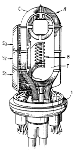
Referring to the drawings, Figures 1 and 2 show a node
N forming part of a ring topography PON. The node N includes
a stack of three splitter array sub-assemblies S1, S2 and S3
and a break-out tray T. A 96 fibre cable C, which forms a
ring (loop) centred on a local exchange (not shown), enters
the break-out tray T via a cable entry portion 2 (see Figure
12) after passing through a node base 1. The cable (then
passes at least twice round a generally oval perimeter track
3 of the tray T, and leaves the tray via the portion 2. The
96 fibres are housed in twelve flexible tubes (not shown)
made of plastics material, each of the tubes containing eight
primary-coated fibres. As is described in detail below with
reference to Figure 12, the tray T includes a break-out
WO 95/07475 b g ~ ~ PCT/GB94/01956
_ g _
region B in which individual fibre end portions, formed by
cutting into one of the tubes, are led to the splitter array
sub-assemblies S1, SL and S3. In this connection, it should
be noted that the tray T stores a sufficient length of the
cable C so that, after cutting one of the tubes in the middle
of this stored length, and stripping back that tube to expose
its optical fibres, each of the originally continuous fibres
forms two fibre end portions whose length is sufficient to be
led to the splitter array sub-assemblies S1, S2 and S3, and to
leave spare fibre which can be stored for future use.
Figures 3 and 4 show the mounting of the node '~ in a
footway box F, a dome-shaped cover D being fixed to the node
base 1 prior to mounting.
One of the spiitter array sub-assemblies, S" is shown
in detail in Figures 5 and 6. The other two sub-assemblies
S~ and S3 are the same as the sub-assembly S1. The sub
assembly S1 includes a stack of ten splice trays 4, each of
which is Smm thick. The trays 4 are supported (in a manner
described below) by a stainless steel chassis 5 constituted
by a top plate 5a, a base plate 5b and a back plate 5c. Each
of the splice trays 4 is a single circuit splice tray, that
is to say, ' n use, it has two incoming optical fibres (one
each ~or transmitting and receiving), and two outgoing
optical fibres (one each for transmitting and receiving).
The three plates 5a, 5b and 5c are welded together, and the
top plate 5a of the sub-assembly S1 can be fixed to the base
plate 5b of the adjacent sub-assembly Sz (not shown in Figures
5 and 6) by means of mounting bolts (not shown). Similar
mounting bolts can be used to fix the plate 5a of the sub-
assembly S1 and the plate 5b of the sub-assembly S3 to support
means (not shown) in the node N.
The chassis 5 also supports an input splitter array
mat 6, an output splitter array mat 7, and a splitter array
back cover 8. In this connection, the input mat 6 carries
(as is described below with reference to Figure 10) fibres
which carry telecommunications signals from the exchange to
customers. These fibres are termed transmit fibres.
WO 95/07475 ~ ~ PCT/GB94/01956
- 10 -
Similarly, the output mat 7 carries fibres which carry
telecommunications signals from customers to the exchange.
These fibres are termed receive fibres. The mats 6 and 7 are
made of a flexible polymer, for example an elastomeric
polymer such as injection mouldable zantoprene, or
polyurethane. The back cover 8 is made of flexible
polypropylene (which is also injection mouldable). This
inherent flexibility ensures that, in use, the mats 6 and 7
are held firmly against the chassis back plate 5c by the back
cover 8.
As shown in Figure 7, each splice tray 4 has a main
body portion 9 and a fibre entry portion 10 which also
constitutes a clip-on test area. Fibre access to the main
body portion 9 from the fibre entry portion 10 is via a
channel 11. The main body portion 9 is of oval
configuration, having an oval base 9a and an upstanding
peripheral wall 9b. A hollow mandrel 12 is provided on the
base 9a adjacent to the entry channel ll. The mandrel 12 is
of rounded square cross-section, is sized to ensure minimum
bend requirements for live fibre passing around it, and has
a f=bre inlet aperture 12a through which dark fibre can pass
for internal storage. A channel 13 is defined between the
mandrel 12 and the peripheral wall 9b, the channel 13 leading
to a furtzer channel 14 which leads around the inside of the
wall to a splice holder region 15. In use, this region 15
houses a splice holder (not shown) for splicing two incoming
fibres to two outgoing fibres. A direction reversing channel
16 leads from the channel 14 adjacent to the region 15 back
to that portion of the channel 14 which adjoins the channel
13 adj acent to the mandrel 12.
The fibre entry portion 10 of each splice tray 4
includes three fibre entry/exit ports 17a, 17b and 17c (see
Figure 8). Diverging channels 18a and 18b are provided to
lead fibre between the port 17a and the channel 11 via
respective apertures 19a and 19b. These apertures 19a and
19b constitute what are known as "clip-on apertures", and
provide easy access to the associated fibres in order to
WO 95/07475 ~ 1 b U ~ 5 ~ PCT/GB94/01956
- 11 -
measure the light passing there along, and hence to determine
the quality of the splices. These clip-on apertures, and
associated light measurement apparatus, are described in the
specification of our International patent application WO
93/00600.
Similar diverging channels 20a and 20b are provided to
lead fibre between the port 17c and the channel 11 via
respective clip-on apertures 21a and 21b. A single channel
22 is provided for leading fibre between the port 17b and the
channel 11. The channel 22 is not provided with a clip-on
aperture.
Each splice tray 4 is also provided with a number of
fibre retention tabs 23 for holding fibre in the various
channels 11, 13, 14, 16, 18a, 18b, 20a, 20b and 22. One of
these tabs (indicated by the reference numeral 23a) is
generally V-shaped, and extends from the curved end of the
peripheral wall 9b remote from the mandrel 12 about halfway
across, and above; that portion of the base 9a between that
wall portion and the mandrel.
Each tray 4 is pivotally mounted on the splitter array
back cover 8 by means of a leash 24 and a retaining ring 25
which are moulded integrally with the rest of the tray. The
leash ~4 of each tray 4 has two arms 24a and 24b joined
together by a hinge 24c. Its retaining ring 25 is a friction
fit within a groove 26 formed in the back cover 8 (see Figure
11). In use, a rod (not shown) passes through all the
retaining rings 25 and through apertures (not shown) in the
top and base plates 5a and 5b. In this way all the splice
trays 4 are retained by their back plates 5c, but each can be
pivoted out away from the other trays in the stack to provide
access to its clip-on apertures 19a, 19b, 21a and 21b. In
this position, the arms 24a and 24b take up a generally
straightline configuration (as opposed to the V-shaped
configuration they have when the tray is in the stack). As
the retaining ring 25 of a pivoted-out tray 4 is held in
position by the retaining rod, the pivotal movement of the
tray is limited by the leash 24 as its two arms 24a and 24b
WO 95/07475 ~ ~ ~ PCT/GB94/01956
- 12 -
straighten out. In the fully pi~;oted-out position (the first
operating position), the fibre entry portion 10 of a tray 4
is exuosed.
Each of the splitter array sub-assemblies SI, S2 and S3
is associated with two fibres (four fibre end portions ) of
the eight fibres in the cut tube of the cable. The remaining
two fibres (four'fibre end portions) from the cut tube are
stored in the break-out tray T as is described below with
reference to Figure 13. As the cable C is in the form of a
ring, telecommunications signals can travel to/from the
exchange in either direction round the ring. For
convenience, one of the directions is termed the main
direction, and the other the standby c~.irection. In practice,
only main fibres will be used for _zormal signalling, the
standby fibres only being used in the eventuality of main
fibre failure.
The two main fibre end portions associated with say
the splitter array sub-assembly S1 pass from the break-out
tray T to the lowest splice tray 4 of that assembly, the
Fibre end portions being supported in, and protected by, a
bend limiting tube 27a (see Figure 6). This bend limiting
tube 27a is a proprietary item made of polypropylene ringed
tubincr which, though flexible, cannot easily be bent beyond
minimum bend radius requirements for live fibre. The bend
limiting tube 27a terminates in the port 17a of the lowest
splice tray 4, and its two fibre end portions are led into
the main body portion 9 via the channels 18a and 18b, the
clip-on apertures 19a and 19b, and the channel 1l. These
fibre end portions are then spliced to the ends of a pair of
fibres which (as is described below) are associated with the
mats 6 and 7. The two splices are then positioned in a
splice holder which is then mounted in the region 15. The
four fibres leading to the splices are then stored in the
main body portion 9 of the tray 4 with two of the fibres (for
example those from the break-out tray T) being led away from
the splices in the channel 14, and the other two fibres being
led away from the splices via the channel 13 and the
WO 95/07475 J ~ PCT/GB94/01956
- 13 -
reversing channel 16. A length of each of the fibres is
stored in the main body portion 9 of the tray 4 by passing
these fibres one or more times round the mandrel 12 and under
the V-shaped tab 23a. The fibres' natural resilience will
ensure that the loops of fibre expand outwardly into a
configuration of varying diameter turns. The provision of
stored fibre permits a minimum of ten re-splices of each of
the splices to be carried out during the lifetime of the
as s embl y.
The two fibres which are associated with the mats 6
and 7 leave the main body portion of the tray 4 via the
channel 11. They are then led to the port 17c of the entry
portion 10 via the clip-on windows 21a and 21b and the
channels 20a and 20b. These fibres are then led to the mats
5 and 7 within a bend limiting tube 27c (see Figure 6). One
of these main input fibres terminates on the input mat 6,
where (as is described below with reference to Figure 10) it
is joined by splitter means to eight output fibres.
Similarly, the other of these main input fibres terminates on
the output mat 7, where it is j oined by splitter means to
sight output fibres.
The two standby fibre end portions associated with
this splitter array sub-assembly Si pass from the break out
tray T to the second lowest splice tray 4 of that assembly.
Here, these two fibre end portions are spliced to two fibres
which are led back to the mats 6 and 7 and so are termed
standby input fibres, and each of the standby input fibres is
joined by splitter means to the same eight output fibres as
the corresponding main input fibre. The fibre arrangement on
this second lowest splice tray 4 is the same as that for the
lowest splice tray. Similarly, fibres enter and leave this
splice tray 4 in bend limiting tubes 27a and 27c.
The remaining eight splice trays 4 in the sub-assembly
S, of Figures 5 and 6 are customer splice trays. As the fibre
arrangement in each of these customer splice trays 4 is the
same, this will be described in detail for only one of these
trays. Thus, one of the output fibres from each of the mats
WO 95/07475 ~ ~ PCT/GB94/01956
- 14 -
6 and 7 (that is to say a transmit fibre and a receive fibre)
is led to the port 17c of a given customer splice tray 4
inside a bend limiting tube 27c. These two fibres are led
into the main body portion 9 of the tray 4 via the channels
20a and 20b, the clip-on windows 21a and 21b, and the channel
11. In use, these fibres are spliced to two fibres of a
four-fibre blown fibre unit associated with a given customer.
Such a unit has four fibres in a single tube, the tube being
fed between the customer and the node N by the well known
fibre blowing technique (see EP 108590). The customer's
blown fibre unit is led to the port 17a of the splice tray 4
within a bend limiting tube 27a. The blown fibre coatings
are stripped away from the four fibres "downstream" of the
port 17a.
Two of the fibres within the unit (the two fibres
which are to be spliced to the transmit and receive fibres
from the mats 6 and 7, and so are termed live fibres ) are fed
to the main body portion 9 of the splice tray 4 via the
channels 18a and 18b, the clip-on apertures 19a and 19b, and
the channel 11. The two other fibres (which are spare fibres
not for immediate use) are fed to the main body portion 9 of
the splice tray 4 via the channels 22 and 11. All four
fibres then pass round the mandrel 12 within the channel 13,
and then back to the mandrel after passing along the channels
14 and 15. The two spare (dark) customer fibres pass through
the aperture 12a and are stored inside the mandrel 12. The
two live fibres pass round the mandrel 12, and are then
spliced to the transmit and receive fibres from the mats 6
and ?, the splices are stored in a splice holder, and the
splice holder is positioned in the region 15. As with the
two lowest splice trays 4, each of the spliced fibres has a
length to be stored (enabling up to ten re-splices to be made
during the lifetime of the assembly), these fibre lengths
likewise being stored by looping them each one or more times
round the mandrel 12 and under the V-shaped tab 23a.
In order to access the splices within a given splice
tray 4, it is necessary to remove the rod holding the
WO 95/07475 216 8 8 5 5 pCTlGB94/01956
- 15 -
retaining rings 25 in position, prior to the pulling that
tray out of the stack sufficiently far to gain access to the
splices. In this position (the second operating position),
the tray 4 is maintained in position by its bend limiting
tubes.
The two spare customer fibres stored within the
mandrel 12 of a given splice tray 4 can be used to replace
the two live fibres of that customer in the event of these
fibres failing. More importantly, however, they can be used
to provide that customer with additional lines or service.
(In this connection, it should be noted that each fibre pair
can provide up to 32 lines using customer premises equipment
(CPE) electronics such as an optical network unit (ONU)
matched to an optical line terminal (OLT) at the exchange.
Each pair of fibres can also provide a Megastream service.)
In this case, the two spare fibres are removed from their
storage position within the mandrel 12, and are led to the
fibre entry portion 10 of the tray 4 via the channels 13 and
11. They then leave the tray 4, via the apertureless channel
22 and the port 17b, and enter a bend limiting tube 27b (see
Figure 6). This tube 27b is routed via the back cover plate
8 to another splice tray 4 - usually a splice tray of another
of the sub-assemblies SZ or S3 of the node N. The tube 27b
terminates at the port 17a of this tray 4, and the two fibres
are led into the main body portion 9 via the channels 18a and
18b, the apertures 19a and 19b, and the channel 11. Here
they are spliced to two "exchange" fibres, and all spare
lengths of fibre are stored in the same manner as that
described above for the other splice trays. In this
connection, the "exchange" fibres could be either a second
pair of fibres from the break-out tray T (direct exchange
fibres ), or a pair of output fibres from the mats 6 and 7
(indirect exchange fibres).
The bend limiting tubes 27a, 27b and 27c of each of
the splice trays 4 are provided with respective support
manifolds M (see Figures 6 and 9). Each manifold M is a
sliding friction fit on a flanged portion (not shown) of the
WO 95/07475 216 ~ ~ ~ ~ pCT/GB94/01956
- 16 -
chassis back plate 5c, and is provided with an open aperture
28a for supporting the associated bend limiting tube 27a, and
with a pair of closed apertures 28b and 28c for supporting
respectively the associated bend limiting tube 27b (if there
is one) and the associated bend limiting tube 27c. The
manifolds M are made of injection moulded filled nylon.
Figure 10 shows the input mat 6 of the sub-assembly S1.
The output mat 7 of this sub-assembly, being of identical
construction to the input mat 6, will not be described in
detail. The mat 6 includes an input slot 29 for receiving
the main input fibre, and an input slot 30 for receiving the
standby input fibre. These two slots 29 and 30 lead to an
aperture 31 which houses a 2x2 fused coupler (not shown).
The two output fibres from this fused coupler are led via a
curved channel 32 around a mandrel 33. The mandrel 33 has a
radius of 30mm, and so fulfils the minimum bend requirements
for live fibre. Each of the fused coupler output fibres is
spliced to an input fibre to a respective 1x4 planar coupler
(splitter). The two splices are stored in a recess 35b.
The two planar couplers (not shown) are housed in an
aperture 34 adj acent to the aperture 31. The two fibres pass
from the mandrel 33 to their planar couplers via the curved
end wall 35a of a recessed portion 35 of the mat 6, and via
respective curved slot 36. The eight output fibres of the
two planar couplers pass round the mandrel 33 via a slot 37.
These fibres then leave the mat 5 via respective output slots
38 which fan out over the recessed portion 35 and the
adjacent raised portion which defines the curved end wall
3 5a.
The mat 6 thus forms a 2x8 splitter for the transmit
fibres, with one of its inputs being the main transmit input
fibre and the other the standby transmit input fibre. As
mentioned above, only main fibres are used in normal
operation, so the mat 6 acts as a 1x8 splitter. However,
should there be problems with the main fibre route, the mat
6 will still act as a 1x8 splitter with the standby receive
fibre as its input fibre.
WO 95/07475 PCT/GB94101956
2168855
- 17 -
Similarly, the mat 7 constitutes a 2x8 splitter for
the receive fibres.
Figure 11 shows the splitter array back cover 8 of the
sub-assembly S1 in greater detail. The back cover 8 is formed
with a pair of longitudinally-extending grooves 8a adjacent
to that end remote from the groove 26. These grooves 8a
reduce the thickness of the back cover in this end region,
and so enhance the flexibility of the back cover, thereby
ensuring that, in use, the back cover holds the mats 6 and 7
firmly against the chassis back plate 5c. In this
connection, it should be noted that this end region of the
back cover 8 is formed with an in-turned L - shaped flange
8b which can be snapped over grooves 28d formed in the
manifolds M to hold the back cover to the chassis 5 with the
i5 mats 6 and ? firmly sandwiched therebetween.
The outer surface of the back cover 8 is also provided
with a plurality of longitudinally-extending ribs 8c, the
base of each rib -being formed with a plurality of apertures
8d. These apertures 8d extend right through the back cover
8 to its inside surface, and constitute a matrix of tie
points for the attachment of cable ties which are used to tie
the bend limiting tubes 27a, 27b and 27c to the sub-assembly
S.
Figure 12 shows the break-out tray T in greater
detail. As mentioned above, two loops of the cable are
stored in the track 3, before the cable exits the break-out
tray ?' via the entry portion 2, and one of the tubes of the
cable is cut in the middle of its stored length. One of the
cut fibres forms the main fibre for the splitter array sub-
assembly shown in Figures 5 and 6, and another the standby
fibre for that sub-assembly. The remaining fibres can be
main and standby fibres for other splitter array sub-
assemblies S~ and S3 of the node N, or can be stored around a
mandrel 39 at that end of the tray T remote from the cable
entry portion 2. The mandrel 39 has a rounded rectangular
cross-section, and is sized so that fibre coiled therearound
does not exceed minimum bend radius requirements.
WO 95/07475 ~ ~ ~ ~ ,~ j ~ PCT/GB94/01956
- 18 -
The break-out region B of the tray T is formed with a
plurality of curved upstanding fingers 40, adj acent pairs of
which define sixteen fibre feed channels 41. The two fibre
end portions that constitute the main fibres associated with
the lowest splice tray 4 of the sub-assembly S1, are fed
through the first channel 41 (that is to say through the
channel nearest the entry portion 2). Similarly, the two
fibre end portions that constitute the standby fibres
associated with the second lowest splice tray 4 are fed
through the second channel 41. (As there are sixteen
channels 41, the break-out tray T can handle sixteen pairs of
fibre end portions, that is to say all the fibre end portions
from two cut tubes.) The two fibres then pass into the bend
limiting tube 27a associated with the lowest splice tray 4 of
the sub-assembly S1. This tube 27a passes through an aperture
42 in a raised portion 43 of the break-out region B (see
Figure 13), and is tied in place by ties (not shown)
associated with a further aperture 44.
A preferred form of TPON includes a 32-way split, that
is to say each fibre from the exchange serves 32 actual
customers via one or more splitting (flexibility) points such
as the node N described above. As the node N defines an S
way split, it could be used as a primary splitting point, in
which case each of the " customer" fibres leaving the node
would lead to a respective secondary splitting point. Each
of the secondary splitting points would be similar to the
node N, but each incoming fibre would be split four ways
rather than eight ways. As the outgoing fibres from a
primary node do not go directly to customers, the terms
"customer splice trays" and "customer fibres" used above
should be taken to mean splice trays and fibres associated
with either actual customers or with downstream splitting
points. Of course, in the preferred 32-way split form of
TPON, the nodes N could also be secondary nodes. In this
case, there would be four nodes N, each serving eight actual
customers, and the four secondary nodes would be served via
a 4-way split primary node. Here again, the primary node,
WO 95/07475 ~ ~ ~ PCT/GB94I01956
- I9 -
would be similar to the node N, but each incoming (exchange?
fibre would be split four ways rather than eight ways.
It will be apparent that the type of splitter array
sub-assembly described above is extremely flexible in that it
can readily be adapted to suit different requirements. In
particular, it is adaptable to any splitting ratio by varying
the number of splice trays used and the size and form of the
splitter array mats 6 and 7. Moreover, by co-locating
several splitter array sub-assemblies in a node, splitting
from a plurality of exchange fibres can be accomplished at
any given point, using different splitting ratios in each
sub-assembly if required.
An important advantage of the sub-assemblies described
above, is that the splitters and the associated fibres can
all be factory fitted. Thus, the fused and planar couplers
and their associated fibres can be made and positioned in the
mats 6 and 7, and the associated fibres can be led to their
splice trays 4 within bend limiting tubes - all at the
factory. When the sub-assembly is to commissioned, the
fitter needs only to cut one or more tubes of the cable C,
feed main and standby fibre end portions to the lowest two
splice trays 4 of the sub-assembly, store spare cut fibre end
portions in the break-out tray T, splice the main and standby
fibre end portions to the main and standby input fibres
already present in the two splice trays, and to splice
"customer" fibres to the fibres already present in the other
splice trays 4. In this way, the amount of skilled work
which has to be carried out on site is reduced to a minimum.
In particular, the fitter does not need to carry out any
intricate splicing for splitting purposes. Moreover, the
bend limiting tubes ensure that the fibres guided therein are
never bent beyond the minimum bend requirements for live
fibre even when the splice trays are pivoted out of the stack
to either of their operating positions. This guarantees the
transmission performance of live fibres carried by the bend
limiting tubes.
The sub-assembly described above could also be adapted
W095/07475 2 ~ ~ g ~ ~~ PCT/6B94J01956
- 20 -
for use in a spur joint. In such a case, no splitting is
requi red, s o the s ub-as s embl y woul d not l ncl ude the mats 6
and 7. In a first type of spur joint, all twelve tubes of
the fibre cable C would be cut, thereby forming twelve main
fibre tube ends and twelve standby fibre tube ends. The
fibres of six of the main f-.ibre tube ends would then be
spliced to the fibres of six of the standby fibre tube ends
in special (single element) splice trays 45 (as is described
below with reference to Figure 14). The fibres of the
remaining six main fibre tube ends are then spliced to
"customer" fibres in 24 splice trays 4. Similarly, the
fibres of the remaining six standby fibre tube ends are
spliced to 48 "customer" fibres in 24 splice trays 4. Thus,
two fibres are fed, in bend limiting tubes, from a breakout
tray (not shown) to each of the 48 splice trays 4, where they
are spliced to "customer" fibres in a similar manner to that
described above with reference to Figures 5 and 6.
A respective main fibre tube end and a respective
standby fibre tube end are fed from the break-out tray to
each of the splice trays 45 (see Figure 14), each tube end
being in a respective bend limiting tube (not shown, but
similar to the bend limiting tubes ~7a, 27b and 27c). Each
tray 45 has a main body portion 46 and a tube entry portion
47. The main body portion 46 is of oval configuration,
having an oval base 46a and an upstanding peripheral wall
46b. Fibre access to the main body portion 46 from the tube
entry portion 47 is via a channel 48. Channels 49, 50, 51
and 5 2 are provi ded l n the mai n body porti on 4 6 to gui de both
main and standby fibres to a pair of splice holder regions
53. The channel 51 is a direction reversing channel, and
permits main and standby fibres to approach each of the
splice holder regions 53 from opposite directions.
Each splice tray 45 is also provided with a number of
fibre retention tabs 54 for holding fibre in the various
channels 49 to 52.
The tube entry portion 47 of each splice tray 45
includes two tube entry/exit ports 55a and 55b. Channels 56a
WO 95/07475 ~ ~ ~ ~ PCT/GB94/01956
- 21 -
and 56b are provided to lead fibre between the ports 55a and
55b and the channel 48.
The splice tray is provided with a leash 57 and a
retaining ring 58 (similar to the leash 24 and the retaining
ring 25 of the tray 4). The leash 57 permits the tray 45 to
be pivoted out of a stack of trays to enable access to the
tube entry portion 47.
In use, a main fibre tube end is led to the port 55a
of each of the splice trays 45, and a standby fibre tube end
is led to the port 55b of each of the splice trays 45.
Inside each tube entry portion 47, the tubes are cut away to
expose the fibres. The fibres are then fed into the main
body portions 46 of the trays, where they are spliced. The
eight splices ~n each tray 45 are then positioned, four in
each of a pair of splice holders, and the splice holders are
then mounted in the regions 53. The fibres leading to the
splices are then stored in the main body portions 46 of the
trays 45. A length of each of the fibres is stored in the
main body portion 46 of the associated tray 45 by passing
these fibres one or more times round an upstanding mandrel 59
and under the tabs 54. The fibres' natural resilience will
ensure that the loops of fibre expand outwardly to a
configuration of varying diameter turns. The provision of
stored fibre permits re-splicing to be carried out during the
'_ifetime of the assembly.
In a modified version of the spur joint described
above, only six of the tubes are cut, the fibres in these
tubes being spliced to "customer" fibres in 48 splice trays
4 as described above. The remaining six uncut tubes are
looped around a break-out tray. Alternatively, instead of
using 48 splice trays 4, six splice trays 45 could be used.
This alternative would, however, only be used in cases where
there is no need to access spur joints for future use.
Obviously, for either type of spur j oint, the number
of fibres forming the spur can be varied. For example, the
spur could be formed from the fibres of one cut tube. In
this case the spur would contain 16 fibres (eight main fibres
WO 95/07475 ~ ~ PCT/GB94/01956
- 22 -
and eight standby fibres from a single cut tube) and 88
fibres (from the remaining eleven tubes - either cut and
spliced or uncut and coiled) would continue through on the
ri ng.