Note: Descriptions are shown in the official language in which they were submitted.
WO95tO4616 2 1 6 8 9 5 7 PCT~S94/09067
TITLE OF THE INVENTION
SPACE FRAME APPARATUS AND PROCESS FOR THE
MANUFAClU~E OF SAME
BACKGROUND OF THE INVENTION
1. Technical Field
The present invention relates in general to frame
structures, and, more particularly, to space frame
apparatuses, and the process for manufacturing same,
wherein such a space frame apparatus is used in the
construction of various vehicles, such as automotive
and aviation vehicles, and wherein the space frame
apparatus is intended to structurally bear a sub-
stantial load of such a vehicle when fully assem-
bled.
2. Background Art
Space frame structures for use in the construction
of vehicles have been know in the art for several
years. Typically, such space frames have been
constructed from a plurality of individual aluminum
alloy extrusions which are joined together at nodes
generally fabricated from cast or wrought shapes.
Each of the nodes generally comprise three to four
connecting regions which each fit into the hollow
sections of the ends of corresponding ones of the
individual extrusions. The ends of the extrusions
may then be secured to the respective nodes through
welding or adhesive bonding. Two examples of such a
wo 95~04616 2 1 6 8 9 5 7 PCT~S94/09067
node-type construction can be found in Browning,
U.S. Pat. No. 4,735,355, and, in an article in the
May 1991 Materials Engineering Magazine, referring
to "Automotive Aluminum."
Although use of nodes for attachment of individu-
al, segmented extrusions, have indeed been utilized,
such a construction has resulted in concerns rela-
tive to the structural integrity of such connections
-- especially inasmuch as both welds and adhesive
bonding have a tendency to fatigue upon exposure of
excessive vibration and stress typically imparted to
such connections during normal operation of a vehi-
cle employing such a space frame structure. Fur-
thermore, when nodes, or the like, are used in a
space frame, the space frame requires numerous
individual extruded frame segments and numerous
nodes for connection therewith. Accordingly, the
costs associated with such a construction, coupled
with concerns from a structural perspective, have
resulted in the need for a better alternative.
Although the above-identified prior art utilizes a
plurality of individual, segmented frame portions in
combination with connecting nodes, other prior art
space frames have been constructed from continuous
frame portions, without reliance upon nodes. One
example of such prior art is Malmurno, U.K. Pat.
Apln. GB 2 131 361 A. Although Malmurno does uti-
lize continuous frame portions, the cross-members
which maintain the outer frame portions in an erect-
ed orientation appear to be merely welded to theframe. Accordingly, the same concerns pertaining to
fatigue of the connection between the cross-member
and the outer frame portions persist -- even without
the use of nodes.
2 1 6895~
WO95/04ClC PCT~S94/09067
Although prior art space frames disclose continu-
ous outer frame portions, as well as means for
connecting cross-members to the frames, none of such
prior art teaches, much less discloses, one or more
continuous outer frame portions which include pre-
~ n~rily pre-softened regions, which are softened
through localized heat induction, and, wherein the
one or more continuous outer frame portions are then
bendable to varying radii in any predetermined
lo direction relative to a particular vehicle configu-
ration. Furthermore, none of such prior art teach-
es, much less discloses attachment of cross-members
to the continuous outer frame portions of a space
frame wherein the respective ends of the cross-
members are insertable into corresponding slotswithin the continuous frame portions, and wherein
the ends of the cross-members include a flange and
collar portion each formed upon softening through
localized heat induction and then deformation -- for
purposes of securely pinching the cross-member to
the inner and outer peripheral surfaces of the
corresponding slots.
It is thus an object of the present invention to
provide a space frame apparatus constructed from one
or more continuous outer frame portions which are
secured in an erected orientation through coopera-
tion with one or more cross-members -- without
reliance upon separate connecting elements, or
nodes.
It is also an object of the present invention to
provide a space frame apparatus wherein secured
connection of the one or more cross-members to the
one or more continuous outer frame portions is
maintained by a compression fit between the flange
wo g~/04616 2 1 6 8 9 5 7 PCT~S94/09067
and collar portion of the ends of the cross-members
about the inner and outer peripheral surfaces of the
corresponding slot shoulders, and wherein such
flange and collar portions are formed by softening
the distal and proximal ends of the cross-members
through localized heat induction and then deforming
same into such a flange and collar configuration.
It is still further an object of the present
invention to provide a space frame apparatus wherein
10 the one or more continuous outer frame portions are
constructed from aluminum extrusions which have a
plurality of predetermined areas pre-softened
through localized heating so that continuous extru-
sions can be bent to varying predetermined radii in
15 predetermined directions relative to a specific
vehicle configuration, and wherein the bent regions
are then allowed to harden toward their original
hardness.
It is yet another object of the present invention
20 to provide a space frame apparatus having superior
structural integrity at the connecting joint between
the cross-members and the continuous outer frame
portions, and which can be manufactured at relative-
ly low costs.
These and other objects of the present invention
will become apparent in light of the present Speci-
fication, Claims and Drawings.
WO9~/04616 2 1 6 8 9 5 7 PCT~S94/09067
DISCLOSURE OF THE INVENTION
The present invention comprises a space frame
apparatus for use in the construction of various
- 5 vehicles, such as automotive and aviation vehicles,
wherein the space frame apparatus is intended to
structurally bear a substantial load of such a vehi-
cle when fully assembled.
The space frame apparatus includes one or more
continuous outer frame means, having one or more
pre-selected attachment regions, for providing an
outer frame for a vehicle, and one or more cross-
member means each having at least a first end opera-
bly attached to the one or more frame means at
corresponding ones of the one or more pre-selected
attachment regions. Such cross-member means serve
to increase the structural rigidity of the appara-
tus, as well as to enable articulation of the one or
more continuous outer frame means into an erected
orientation.
Slot means, having an inner and outer peripheral
surface, are integrally formed through at least a
portion of the one or more pre-selected attachment
regions for operably accepting at least a portion of
corresponding respective ones of the at least first
ends of the one or more cross-member means. Secure-
ment means are operably associated with at least a
portion of each of the first ends of the one or more
cross-member means and the corresponding slot means
for operably securing the first ends within the
corresponding slots means, to, in turn, securely
maintain the space frame apparatus in the erected
orientation. The securement means further include
at least a portion of the first ends of the cross-
wo 95~04616 2 1 6 8 9 5 7 PCT~S94/09067
member means being softened through localized heat-
ing, and then deformed, so as to maintain the re-
strained operable positioning of the first end
within the corresponding slot means.
In the preferred embodiment of the invention, the
operable acceptance of the first ends of the cross-
member means within the corresponding slot means
describes a joint therebetween the cross-member
means and the one or more continuous outer frame
lo means. Furthermore, strength enhancement means are
operably associated with the joint for imparting
increased structural integrity thereto, to, in turn,
increase rigidity against imparted stress at the
joint.
In this preferred embodiment of the invention, the
one or more cross-member means further includes an
interior surface defining a channel region and a
wall having a finite thickness. The strength en-
hancement means comprises at least one sleeve mem-
20 ber, or ferrule, operably positioned within at leasta portion of the channel region of the one or more
cross-member means adjacent the interior surface of
at least the first end of same -- so as to reinforce
the finite wall thickness of the cross-member means
25 within the joint.
Each of the at least first ends of the one or more
cross-member means have an inner dimension, and, the
at least one sleeve member has an outer dimension so
as to collectively describe an interference fit
30 therebetween. Accordingly, the interference fit
additionally serves to maintain the sleeve member
within at least a portion of the channel region of
the first end of a corresponding one of the one or
more cross-member means.
_ WO95/04616 2 1 6 8 9 5 7 PCT~S94/09067
In one preferred embodiment of the invention, the
sleeve member includes an inner edge operably posi-
tioned within the channel region of a corresponding
one of the at least first ends of the one or more
cross-member means, and an outer edge extending
through and past a corresponding one of the slot
means.
The securement means further includes at least a
portion of the outer edge of the sleeve member being
softened through localized heating, and then de-
formed, so as to result in a flange portion operably
positioned adjacent the outer peripheral surface of
the slot means to, in turn, further enhance secure-
ment of respective ones of the at least first ends
of the one or more cross-member means within the
corresponding slot means.
The at least first ends of the more or more cross-
member means each include a proximal end operably
positionable adjacent the inner peripheral surface
of the slot means. Each of the proximal ends may be
softened through localized heating, and then de-
formed, so as to form a detent, or collar portion,
adjacent the inner peripheral surface of a corre-
sponding one of the slot means.
In one embodiment of the invention, the slot means
have an inner dimension, and each of the at least
first ends of the one or more cross-member means
have an outer dimension so as to collectively de-
scribe an interference fit therebetween. The inter-
ference fit serves to maintain at least a portion ofthe first ends of the one or more cross-member means
within at least a portion of a corresponding one of
the slot means.
In the preferred embodiment of the invention, the
WO95/04616 2 1 6 8 9 5 7 PCT~S94/09067
at least first ends of the one or more cross-member
means each include a distal end and a proximal end
wherein the distal end extends through and past the
corresponding slot means in which the first end is
positioned. The securement means further includes
the distal and proximal ends being softened through
localized heating, and then deformed, so as to form
a detent, or collar portion, adjacent the inner
peripheral surface of a corresponding one of the
lo slot means, and, one or more flanged regions opera-
bly positioned adjacent the outer peripheral surface
of the corresponding slot means. Accordingly, such
a flange/collar configuration creates a substantial-
ly locked joint relative to the at least first end
of the one or more cross-member means and the corre-
sponding slot means.
In another preferred embodiment of the invention,
the one or more continuous outer frame means com-
prise two or more continuous outer frame portions.
The two or more continuous outer frame portions
include one or more pre-softened regions softened
through localized heating for facilitating bending
of the two or more continuous outer frame portions
at varying radii in any desired direction. Each of
these continuous outer frame means may be construct-
ed from a single unitary member, or, alternatively,
from a first half and a second half which are opera-
bly secured together so as to collectively form a
unitary frame portion.
In the preferred embodiment of the invention, the
one or more continuous outer frame means and the one
or more cross-member means are each constructed of
an aluminum material from the group comprising 6000-
series alloys of varying hardnesses, such as a 6061-
21 68957
WO95tO4616 PCT~S94/09067
T6 aluminum alloy.
The invention includes the process of manufactur-
ing a space frame apparatus wherein the space frame
apparatus is constructed with one or more bendable
outer frame members having pre-selected attachment
regions located thereon. The process includes the
steps of a) forming slots in the one or more bend-
able outer frame members at the pre-selected attach-
ment regions, wherein the slots include an inner
10 peripheral surface and an outer peripheral surface;
b) softening predetermined areas on the one or more
outer frame members through localized heating; c)
bending the one or more bendable outer frame members
at each of the predetermined areas to varying prede-
termined radii in predetermined directions relativeto a specific vehicle configuration; d) at least
partially hardening the predetermined softened areas
after bending the one or more bendable outer frame
members so as to increase structural integrity to
the predetermined areas; e) forming at least one
cross-member with at least a first end having a
distal end, a proximal end and a cross-sectional
configuration; f) softening the proximal ends of
the at least one cross-member through localized
heating; g) deforming at least a portion of the
softened proximal ends of each of the first ends so
as to alter the pre-deformed cross-sectional config-
uration of same, to, in turn, create a detent por-
tion operably positioned adjacent the inner periph-
eral surface of a corresponding slot for precludingover insertion of the first ends into the corre-
sponding slots in the one or more outer frame mem-
bers; h) inserting the first end of the at least one
cross-member in a corresponding one of the slots in
WO95/04616 2 1 6 8 9 5 7 PCT~S94/09067
the bent one or more outer frame members so as to
form a joint therebetween each respectively; and i)
hardening the locally softened proximal ends back
toward the pre-softened hardness.
In the preferred embodiment of the invention, the
process for manufacturing a space frame apparatus
further includes the steps of softening the distal
ends of the first ends of the at least one cross-
member through localized heating; deforming at least
a portion of the softened distal ends of the first
~nds of the at least one cross-member so as to form
a flange portion operably positioned adjacent the
outer peripheral surface of corresponding ones of
the slots; and, hardening the locally softened
distal ends back toward their pre-softened hardness,
after the step of softening the proximal ends of the
at least one cross-member through localized heating.
Accordingly, these flanged portions, in cooperation
with the detent/collar portions, serve to lockably
secure the cross-members to the continuous outer
frame members by way of a compression fit.
In another embodiment of the invention, the proc-
ess of manufacturing a space frame apparatus further
includes the step of increasing structural integrity
to the joint after the step of forming the at least
one cross-member. This step of increasing the
structural integrity to the joint comprises the step
of inserting at least a portion of a sleeve member,
or ferrule, within at least a portion of the at
least first end of the at least one cross-member
prior to the step of inserting the at least first
end of the at least one cross-member in correspond-
ing ones of the slots.
In this preferred embodiment, the sleeve member
2 1 68957
WO9~/~616 PCT~S94/09067
_
1 1
includes an outer end and an inner end, and the at
least first ends of the at least one cross-member
- includes a channel region. The step of inserting
the at least first ends of the at least one cross-
member in corresponding ones of the slots further
includes the steps of inserting the inner end of the
sleeve member within the channel regions of the at
least one cross-member; inserting the at least first
ends of the at least one cross-members, and, in
lo turn, the sleeve member, into a corresponding one of
the slots until at least a predetermined portion of
the outer end of the sleeve member extends past the
outer peripheral surface of a corresponding one of
the slots; softening the outer end of the sleeve
member through localized heating; deforming at least
a portion of the softened outer end of the sleeve
member so as to form a flange portion operably
positioned adjacent the outer peripheral surface of
the corresponding slot; and hardening the locally
softened outer end of the sleeve member back toward
its pre-softened hardness.
In yet another embodiment, the process of manufac-
turing a space frame apparatus further includes the
steps of extruding a billet so as to form one or
more substantially straight extrusions to be used as
the one or more bendable outer frame members, prior
to the step of forming slots in the one or more
bendable outer frame members at the pre-selected
attachment regions. In addition, the step of bend-
ing the one or more bendable outer frame members ateach of the predetermined areas to varying predeter-
mined radii in predetermined directions relative to
a specific vehicle configuration further includes
the step of positioning the bent portions of the one
wo 9S/04616 2 1 6 8 9 5 7 PCT~S94/09067
12
or more bendable outer frame members in any desired
dimension, so as to form a space frame apparatus
constructed from one or more continuous outer frame
members.
21 68957
WO95/04616 PCT~S94/09067
-
13
BRIEF DESCRIPTION OF THE DRAWINGS
-Fig. l of the drawings is a perspective view of a
prior art automotive space frame showing, in partic-
5 ular, the plurality of individual segmented frame
portions and the plurality of connecting nodes used
for connecting each of the individual segments
together;
Fig. 2 of the drawings is an enlarged sectional
l0 view, in partial cross-section, of a prior art
connecting node of Fig. l, showing, in particular,
the operable positioning of the ends of the nodes
into hollow end regions of corresponding ones of the
individual segmented frame portions, and, into the
hollow ends of the corresponding cross-members;
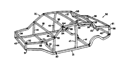
Fig. 3 of the drawings is a perspective view of
the present space frame apparatus showing, in par-
ticular, the substantially uninterrupted continuous
outer frame means, the cross-member means used to
20 maintain the continuous outer frame means in an
erected orientation, as well as the flanged portions
of one of the ends of each of the cross-member means
operably secured against the outer peripheral sur-
face of a corresponding slot means;
Fig. 4 of the drawings is a perspective view of a
substantially linear shaft which is used to form one
of the continuous outer frame means of Fig. 3,
showing, in particular, the slot means operably
formed at predetermined locations thereon, as well
as the pre-softened regions which will facilitate
appropriate bending thereat;
Fig. 5 of the drawings is an enlarged cross-sec-
tional view of one of the cross-member means of Fig.
l as well as the corresponding slot means of the
wo g5tO4616 2 1 6 8 9 5 7 PCT~S94/09067
14
continuous outer frame means, showing, in particu-
lar, the collar portion and flange portion of the
end of the cross-member means operably compressing
the inner and outer peripheral surfaces, respective-
ly, of the slot means so as to result in a lockedcompression fit of the cross-member to the continu-
ous outer frame means, as well as showing an option-
al ferrule inserted within the channel region of the
end of the cross-member means;
Fig. 6 of the drawings is an enlarged cross-sec-
tional view of a cross-member means secured to a
corresponding slot means in the continuous outer
frame means, showing, in particular, the pinched, or
crimped, collar portion of the cross-member means
operably positioned adjacent the inner peripheral
surface of the slot means;
Fig. 7 of the drawings is an enlarged cross-sec-
tional view of an alternative embodiment of the
invention, showing, in particular, a substantially
solid I-beam construction for the continuous outer
frame means, as well as the lockable securement of
one end of the cross-member means to a slot in the
I-beam, as well as showing an alternative double-
backed flange portion of the cross-member means
25 operably positioned adjacent the outer peripheral
surface of the corresponding slot;
Fig. 8 of the drawings is an enlarged cross-sec-
tional view of the cross-member means of Fig. 7,
showing, in particular, the operable positioning of
30 a sleeve member within the channel region of the end
of the cross-member, as well as showing the flanged
outer end of the sleeve member operably positioned
adjacent the flange portion of the cross-member
means;
wo 95/04616 2 1 6 8 9 5 7 PCT~S94/09067
-
Fig. 9 of the drawings is an enlarged cross-
sectional view of a cross-member means operably
secured within a slot of an alternative embodiment
of the continuous outer frame means, showing, in
- 5 particular, the first and second halves of the con-
tinuous outer frame means which collectively de-
scribe a single, unitary frame portion; and
Fig. 10 of the drawings is an elevated enlarged
break-away perspective view of the continuous outer
frame means of Fig. 9, showing, in particular, the
collar and flange portion of a corresponding cross-
member means operably positioned adjacent the inner
and outer peripheral surfaces, respectively, of the
corresponding slot means.
WO95/04616 2 1 6 8 9 5 7 PCT~S94/09067
16
BEST MODE FOR CARRYING OUT THE INVENTION
While this invention is susceptible of embodiment
in many different forms, there is shown in the
drawings and will herein be described in detail,
several specific embodiments, with the understanding
that the present disclosure is to be considered as
an exemplification of the principles of the inven-
tion and is not intended to limit the invention to
the embodiments illustrated.
Prior art automotive space frame 20 is shown in
Fig. 1 as including a plurality of tubular individu-
al frame portions, such as individual frame portions
22 through 24, a plurality of tubular cross-members,
such as cross-members 26 and 27, and a plurality of
connecting elements, or nodes, such as node 21 (Fig.
2). As shown in detail in Fig. 2, each of the nodes
include insertion ends, such as insertion ends 28
and 29, which are insertable into the hollow end
20 portions of corresponding ones of the individual
frame portions, such as frame portions 22 and 23,
and into the hollow end portions of corresponding
ones of the cross-members, such as cross-members 26
and 27. Actual securement of the insertion ends of
the nodes within the hollow ends of the prior art
cross-members and within the individual frame por-
tions can be accomplished through conventional
welding techniques and/or through the use of adhe-
sive bonding. Once fully connected, prior art space
frame 20 will include two outer frame members 25 and
25' comprised of a plurality of individually con-
nected frame portions, a plurality of connecting
nodes, and a plurality of cross-members which will
maintain the outer frame members in an erected
WO95/04616 2 1 6 8 9 5 7 PCT~S94/09067
17
orientation.
Space frame apparatus 30 of the present invention
- is shown in Fig. 3 as comprising two continuous
outer frame means 31 and 32 and cross-member means
- 5 34 through 48. Continuous outer frame means 31 and
32 both include a plurality of pre-selected attach-
ment regions (slot means), such as slot means 50
through 58, as shown more clearly on substantially
linear shaft 31' (Fig. 4), which will be used to
form continuous outer frame means 31, and a plural-
ity of bent regions, such as bent regions 61 through
66. As will be further explained in detail herein-
below, each of the bent regions are formed as the
result of softening predetermined locations 61'
through 66' on substantially linear shaft 31' (Fig.
4) through localized heating, and then bending the
shaft at each of the predetermined softened loca-
tions to varying predetermined radii in predeter-
mined directions so as to conform to a specific
vehicle configuration, such as the vehicle configu-
ration shown in Fig. 3. Slots, such as slot 52
(Fig. 5), which operably accept a portion of corre-
sponding ones of the cross-member means, such as
cross-member means 36, each include an inner periph-
eral surface 90, an outer peripheral surface 91 andan inner dimension 92.
Cross-member means, such as cross-member means 36,
is shown in Fig. 5, as including a first end, such
as first end 70, a second end (not shown), an inte-
rior surface, such as interior surface 72, and aninner dimension defining a channel region 73. The
first and second ends of the cross-member means each
include a distal end, such as distal end 80, having
a flange portion, such as flange portion 83, and a
21 68957
WO 95/04616 PCT/US94/OgO67
18
proximal end, such as proximal end 8l, having a
detent, or collar portion, such as collar portion
82. In this embodiment, collar portion 82 may be
formed by swaging first end 70 of the cross-member
means -- although other techniques for forming the
collar, such as by pinching or crimping, are also
contemplated.
Each of the first and second ends of the cross-
member means are operably inserted into a corre-
sponding slot, such as corresponding slot 52 (Fig.5) where they are then secured in place so as to
maintain space frame apparatus 30 in an erected
orientation, as shown in Fig. 3. As will be ex-
plained in detail, such securement results from a
locked joint between the ends of the cross-member
means and the corresponding slots. Such a locked
joint is achieved as the result of the collar por-
tion, such as collar portion 82, of the cross-member
means, such as cross-member means 36, compressing
against inner peripheral surface, such as inner
peripheral surface 90, of corresponding slot 52, and
then forming and positioning flange portion, such as
flange portion 83, so that it is squeezing against
outer peripheral surface, such as outer peripheral
surface 9l, of corresponding slot 52 -- so as to
result in a compression fit therebetween. As will
also be explained, such flanged and collared por-
tions are formed by softening the respective distal
and proximal ends of the cross-member means through
localized heating, and then deforming same until the
collar and flange portions are created.
Strength enhancement means 95 is shown in alterna-
tive form in Fig. 5 as comprising a sleeve member,
or ferrule, having an outer surface 96, an inner
21 68957
WO95/04616 PCT~S94/09067
edge 97, and an outer edge 98. The sleeve member is
inserted within channel region 73 of a respective
end, such as first end 70, of cross-member means,
such as cross-member means 36, so as to increase
- 5 rigidity to the joint formed upon insertion of the
respective ends of the cross-member means within the
corresponding slot means, such as slot means 52.
Securement of sleeve member 95 to the cross-member
means can be obtained by way of an interference fit
10 between outer surface 96 of the sleeve member and at
least a portion of channel region, such as channel
region 73 (Fig. 5), of the respective end of the
corresponding cross-member means -- although other
conventional securement techniques, such as welding
15 or adhesive bonding of the sleeve member to the
cross-member means are also contemplated. Also
shown in Fig. 5 is an alternative construction of
the continuous outer frame means wherein the contin-
uous outer frame means may be constructed from two
20 halves 125 and 126 which are secured together by
keyed portions 127 and 128. In addition to such
keyed portions, further securement can be maintained
by, for example, welding.
An alternative construction of collar portion
25 82' is shown in Fig. 6 wherein the collar portion is
operably positioned adjacent inner peripheral edge
90 of corresponding slot means 52. Such a collar
portion is formed as the result of pre-softening
proximal end 81 of first end 70 of the cross-member
30 means, and then pinching the softened region until
the collar is formed -- as opposed to swaging.
Although this embodiment is shown without the use of
a ferrule, such reinforcement is indeed contemplat-
ed.
wo 95/04616 2 1 6 8 9 5 7 PCT~S94/09067
Cross-member means 36' is shown in Fig. 7 and Fig.
8 as being operably attached within a corresponding
slot means, such as slot means 52', of continuous
outer frame means 100 (Fig. 7) having I-beam config-
uration. The corresponding cross-members means,
such as cross-member means 36', is operably secured
within slot means 52', and, in turn, to continuous
outer frame means 100, through a compression fit,
wherein the flange and collar portions 83' and 82'',
lo respectively, of the cross-member means, are opera-
bly squeezed and maintained about extending portions
103 and 104 of the I-beam.
Also shown in Fig. 7 and Fig. 8, is alternative
double-backed flange portion 106 (Fig. 7) which may
15 be used for providing additional securement to the
locked joint, as well as utilization of sleeve
member 110 (Fig. 8). Although the sleeve member has
substantially the same configuration as that of
sleeve member 95, as shown in Fig. 5, sleeve member
20 110 additionally includes outer end 98' having a
flange portion 112 which extends beyond the outer
peripheral surface of the corresponding slot means,
as well as past flange portion 83' (Fig. 8) of the
corresponding cross-member means. Such a flange on
25 the sleeve member can be used to provide additional
securement to the joint, and/or additional secure-
ment to the cross-member means itself. Although not
shown, such additional securement can be further
obtained through welding or bending the sleeve
30 member, through adhesive, to the end of a corre-
sponding cross-member means. Furthermore, it is
also contemplated that when such a flanged sleeve
member is used, the distal end of the corresponding
end of the cross-member means may be constructed
WO95/0~16 2 1 6 8 9 57 PCT~Sg4/09067
21
without a flange portion. Accordingly, lockable
engagement of the cross-member means to the continu-
ous outer frame means will occur through a compres-
sion fit, adjacent a corresponding slot, as a result
of the flange on the sleeve member, and the collar
portion on the proximal end of a respective end of
the cross-member means, squeezing the respective
inner and outer peripheral surfaces of the corre-
sponding slot means.
lo An alternative embodiment of continuous outer
frame means 130 is shown in Fig. 9 and Fig. lO as
comprising first half 131 and second half 132. Each
of these halves include lip portions 133, 134 and
135, 136, respectively, which are secured together
so as to form a single unitary frame portion. When
such a configuration is utilized, a predetermined
segment of the lip portions will be removed upon
formation of the slots so as to facilitate operable
acceptance of the corresponding ends of the cross-
20 member means, and in turn, formation and position ofthe flange and collar portions about same. Although
substantially rectangular and I-beam configured
continuous outer frame means have been shown, other
configurations, such as circular and hexagonal,
25 among others, are also contemplated.
The process for constructing space frame apparatus
30 ~Fig. 1) is achieved by first extruding linear
sections, such as linear section 31' (Fig. 4) and
then quenching the extrusions at press. Although
3 several types of material can be used for such
extrusions, aluminum alloys of the 6000-series of
having varying hardnesses are preferred. Further-
more, although hollow extrusions are preferred for
purposes of fabricating the one or more continuous
WO9~/04616 2 1 6 8 9 5 7 PCT~S94/09067
outer frame means 31 and 32 (Fig. 1) (due to their
relatively light weight and minimized material
requirements) solid extrusions, such as extrusions
having an I-beam configuration 100 (Fig. 7), as well
as non-extruded sections, are also contemplated for
use.
After the extrusions have been quenched, they are
substantially straightened and then heat treated and
cut to a particular length suitable for the particu-
lar vehicle configurations required. Accordingly,once Clt to length, a required number of slots, such
as slots 50 through 58 (Fig. 4), are formed in the
extrusions for eventual acceptance of the end por-
tions of corresponding cross-members 34-48 (Fig. 3).
Such slots can be formed through a punching opera-
tion, in conformance with a predetermined pattern
relative to the structural connection required for a
specific vehicle configuration, or, they may be
formed by any other conventional slot forming tech-
20 niques.
After the slots have been formed in the extru-
sions, a specified number of predetermined regions,
such as predetermined regions 61' through 66' (Fig.
4), are softened through localized heating so as to
at least temporarily increase ductility to the
linear extrusions at the predetermined softened
regions. One such acceptable method for softening
the predetermined regions by localized heating is
disclosed in U.S. Pat. No. 4,766,664, issued to
30 Joseph C. Benedyk, for a Process for Formation of
High Strength Aluminum Ladder Structures. In such a
process, an induction coil is placed in operable
contact with the specific area to be heated, and, in
turn, softened -- with only minimal conductivity to
WO9~/04616 2 1 6 8 9 5 7 PCT~S94/09067
adjacently positioned portions of the softened
region. Although the use of an induction coil can
be used (such as disclosed in U.S. Pat. No.
4,766,664), other types of conventional heating
processes for temporarily increasing ductility to
localized areas are also contemplated.
After the longitudinal extrusions have been local-
ly softened, each of the predetermined regions are
bent to varying radii in predetermined directions
10 relative to a specific vehicle configuration. It is
contemplated that such bending be performed either
manually, or on automated bending equipment pre-
programmed with the particular bending requirements
and bending locations relative to specific vehicle
15 configurations. Accordingly, such bending will
result in the formation of one or more continuous
outer frame portions, such as outer frame portions
31 and 32 (Fig. 3), constructed substantially from a
single, substantially uninterrupted extrusion.
Upon completion of the formation of the continuous
outer frame portions, each of the locally softened
regions are then allowed to harden toward their pre-
softened hardness, as desired. The amount of hard-
ness which will be regained will be dependent upon
25 the specific type of alloy used for formation of the
continuous outer frame portions, the amount of
precipitation in the alloy prior to heating, inten-
sity of the heat applied, as well as the length of
time in which the heat is applied to the specific
30 predetermined regions.
In addition to the continuous outer frame members
being extruded, the process also includes extruding
cross-members 34-48 (Fig. 3) to have first ends,
such as first end 70 (Fig. 5), second ends (not
wo 95/04616 2 1 6 8 9 5 7 PCT~S94/09067
24
shown), and a distal and proximal end, such as
distal and proximal ends 80 and 81 (Fig. 5), respec-
tively, at each of the first and second ends. After
the cross-members have been extruded, the respective
proximal ends are locally softened by the same or
similar localized heating process as that used for
the continuous outer frame members. Once softened,
the proximal ends are deformed so as to form a
collar portion, such as collar portions 82 (Fig. 5)
and 82' (Fig. 6). The formation of collar portion
82 (Fig. 5) may be accomplished through the use of
conventional swaging techniques, while formation of
collar portion 82' (Fig. 6) may be formed by merely
pinching, or crimping the softened portion of the
cross-member. After the collar portions are formed,
they are allowed to harden back toward their pre-
softened hardness through conventional hardening
methods.
Once the collar portions have been formed, the
respective first and second ends of the cross-member
means can be operably inserted within a correspond-
ing slot, such as slot 52 (Fig. 5), until distal
ends, such as distal end 80, extends through and
past outer peripheral surface, such as outer periph-
eral surface 91, of the slot so as to form a jointtherebetween. After the joint has been created,
distal ends, such as distal end 80, can be softened
through localized heating and then deformed so as to
form a flange portion, such as flange portion 83
(Fig. 5) which is then allowed to harden back toward
its pre-softened hardness. The flange portion and
the collar portion will be situated so that the
flange portion is squeezing against the outer pe-
ripheral surface, such as outer peripheral surface
WO95/04616 2 1 6 8 9 5 7 PCT~S94/09067
91 (Fig. 5) of the corresponding slot 52, and collar
portion 82 will be squeezing against the inner
peripheral surface, such as inner peripheral surface
90, of the slot so as to result in a compression fit
- 5 therebetween, to, in turn, lock the respective
cross-members to the continuous outer frame por-
tions.
Should additional reinforcement of the joint be
required, insertion of a sleeve member, or ferrule,
10 such as sleeve member 95 ~Fig. 5), or sleeve member
110 (Fig. 8) within the channel region, such as
channel region 73 (Fig. 5) of the first and second
ends of the cross-members can be used. As shown in
Fig. 5, such a sleeve member can be inserted com-
15 pletely within the channel region of the respectiveends of the cross-members, and, in turn, completely
within the corresponding slot. Alternatively, the
sleeve members can have their outer ends, such as
outer end 98' (Fig. 8), extending beyond the distal
20 ends of the respective end of the corresponding
cross-member. Accordingly, when such an end extend-
ing sleeve member is used, its outer end can be
softened through localized heat induction, and then
deformed so as to create a flange portion 112 (Fig.
8) for further securement with and/or to the cross-
member. Such a sleeve member can be further at-
tached to the cross-member through an interference
fit therebetween and/or through welding or adhesive
bonding.
The foregoing description and drawings merely
explain and illustrate the invention and the inven-
tion is not limited thereto except insofar as the
appended claims are so limited as those skilled in
the art who have the disclosure before them will be
WO95/04616 2 1 6 8 9 57 PCT~S94/09067
26
able to make modifications and ~ariations therein
without departing from the scope of the in~ention.