Note: Descriptions are shown in the official language in which they were submitted.
CA2169007
PHOTOGRAPHIC FILM PROCESSING APPARATUS
BACKGROUND OF THE INVENTION
FIELD OF THE INVENTION
The present invention relates to a photographic film processing apparatus for
processing a long developed photographic film formed by joining a plurality of
films with a splicing material.
DESCRIPTION OF THE RELATED ART
In processing exposed photographic film with a small automatic developing
io unit, films in respective clients' orders are developed separately, one
after another.
However, it is inefficient to process one film after another. For processing
with a large automatic developing unit, therefore, exposed photographic films
in a plurality of orders are joined at the ends with a splicing material (e.g.
splice
tape) to form a long photographic film. The long photographic film is
continuously
is developed and taken up in the form of a roll.
The developed photographic film taken up in a roll is subjected to a printing
process by an automatic printing unit. In conventional practice, for example,
the long film is passed through the printing process and taken up in a roll
again,
and subsequently the film is cut order by order by a cutting device.
2o Developed photographic film such as an ordinary 135 film, for example,
may be a film with full-size or panorama-size frames 36mm long each, or a film
with half-size frames l7mm long each.
No problem arises where the automatic printing unit can cope with all sizes
at high speed. However, the full size and panorama size require different size
25 pieces of printing paper and different degrees of enlargement. In the case
of
half size, the direction of printing paper is variable between longitudinal
and
transverse, besides a different degree of enlargement. Thus, in practice,
there
are limitations to what the automatic printing unit can do.
Conventionally, where a long photographic film includes panorama-size and
-1-
half-size films, the long film is subjected to a printing process and taken up
in a
roll, while printing only the full-size film first, skipping the panorama-size
and
half-size films. Subsequently, the panorama-size and half-size films are
printed,
and the long film is cut for respective orders. Where film in one order has a
s mixture of full-size and panorama-size films, similarly the full-size film
is
printed first, and then the panorama-size film, followed by a cutting process.
Thus, varied image lengths may be present in a long photographic film
formed by joining a plurality of films with a splicing material. This gives
rise
to a problem, with the conventional apparatus, of requiring very complicated
io and inefficient processes from printing to cutting.
SUMMARY OF THE INVENTION
In order to solve the problem encountered in the prior art noted above, the
object of the present invention is to provide a photographic film processing
is apparatus for carrying out various exposing processes including a printing
process
efficiently and speedily even for a long developed photographic film formed by
joining a plurality of films with a splicing material.
The above object is fulfilled, according to the present invention, by a
photographic film processing apparatus comprising:
2o a first transport device for transporting a long developed film formed by
joining photographic films with a splicing material;
a joint detecting device for detecting a region of the splicing material in
the
long developed film;
a main cutter for cutting the long developed film transported by the first
2s transport device, in the region of the splicing material to form short
films; and
a second transport device for transporting the short films to exposure
processing units.
That is, the main cutter cuts the long developed film into short films prior
to
an exposing process, and the second transport device transports the short
films
-2-
~~~i~9~0~'
to the exposure processing units.
With the above construction, the long film is cut into short films
corresponding
to respective orders from clients. These short films are transported to the
exposure processing units.
s After the long film is cut into short films corresponding to the respective
orders, the short films having special image frames such as panorama-size or
half-size frames are excluded once before reaching the exposure processing
units. Those short films having only full-size image frames are transported to
the exposure processing units. Alternatively, an appropriate measure may be
io taken to omit an exposing process for the short films having special size
image
frames. This apparatus avoids the complicated practice of the prior art. That
is,
in the prior art, films in a long spliced film having only full-size image
frames
are processed by the exposure processing units and the long film is taken up
in a
roll. Then films having special size frames are processed by the exposure
is processing units. Thereafter the long film is cut order by order. Thus, the
apparatus according to the present invention carries out various exposing
processes
efficiently as a whole.
Where the exposure processing units can cope with the full size and
panorama size of the same image frame length, only half-size films having a
2o different image frame length may be excluded. Where the exposure processing
units can cope with full size and half size, only the panorama size films may
be
excluded.
Apart from the presence of special size films, the long photographic film
could include films unfit for an exposing process because of an extreme degree
2s of over-exposure or under-exposure. An appropriate measure may be taken to
f
exclude such films.
In a preferred embodiment of the present invention, a loop storing device is
disposed on a transport line formed by the first transport device and the
second
transport device for storing the long developed film in loop form. This
construction
-3-
CA2169n07
enables a smooth operation by absorbing or eliminating any time lag between
the process of cutting the long photographic film by the main cutter and the
processes by the exposure processing units.
In another embodiment of the invention, a discharge device is interposed
s between the main cutter and the exposure processing units for discharging
film
fragments cut by the main cutter from a transport line formed by the first
transport device and the second transport device. With this construction, film
fragments resulting from the cutting process may automatically be discharged
from the film transport line. Consequently, the film transport is not affected
by
io cut, unwanted parts of the film.
In a further embodiment of the invention, a film propriety distinguishing
device is disposed on a transport line formed by the first transport device
and
the second transport device for determining whether the short films are fit
for
processing by the exposure processing units. The film propriety distinguishing
is device distinguishes, without requiring observation by the operator, image
frames
of special lengths mixed into the long developed photographic film or presence
of films having overexposed image frames, for example. This automatic
distinguishing operation realizes improved efficiency and reliable results of
distinguishment.
2o The processing apparatus may further comprise a process averting device for
averting, from processing by the exposure processing units, those of the short
films determined by the film propriety distinguishing device to be unfit.
Preferably, the process averting device defines a branch line for branching
the
short films determined to be unfit from the transport line. A simple
additional
2s construction consisting of the branch line enables an automatic removal of
unfit
photographic films before reaching the exposure processing units, to smooth
the
processing by the exposure processing units.
Preferably, the discharge device defines a discharge passage extending
downward from the transport line for guiding cut film fragments including
-4-
~A~~ ~900~
small fragments from film regions adjacent the splicing material and a large
fragment including a film leader connected to a forwanl end of the long
developed
film, the discharge passage including a partition mounted in an intermediate
position thereof for allowing passage of only the small fragments and
deflecting
the large fragment. Thus, large and small film fragments all fall into the
discharge passage, and the large fragment including the leader is deflected by
the partition. Generally, the leader is larger than the fragments cut from the
region of the splicing material in the photographic film. Utilizing this fact,
the
leader may be collected separately from the fragments cut from the splice
region
io of the photographic film by the simple construction consisting of the
partition
disposed in an intermediate position of the discharge passage.
Further, the partition may be disposed in such a position that the large
fragment is transported by the transport line until a forward end of the film
leader reaches the partition. Then, the leader advancing through the discharge
is passage is controlled with respect to position and inclination transversely
of the
advancing direction. Thus, the leader is restrained from shifting or inclining
to
varied extents transversely of the advancing direction, thereby to realize
reliable
sorting of the leader.
The invention proposes that the discharge device includes a branching
20 opening defined in a side wall of the discharge passage above the partition
for
allowing passage of the large fragment. This opening is provided in order to
separate the leader positionally and clearly from the small fragments which
are
to be discarded, so that the leader may be recovered, with priority, for
reuse.
To remove the cut fragments with greater assurance, the discharge device
2s may include a movable guide disposed in a region of intersection between
the
transport line and the discharge passage to be switchable between a posture
for
guiding the short films to advance along the transport line and a posture for
guiding the film fragments cut by the main cutter into the discharge passage.
To ensure that the region of the splicing material does not adversely affect
-5-
~C~21b9007
the film transport when the short films are transported and processed at the
same time, the processing apparatus in a preferred embodiment further
comprises
an auxiliary cutter for cutting lateral portions of the region of the splicing
material in the long developed film.
According to this construction, when the main cutter is operated to cut the
long photographic film in the region of the splicing material to a short film
corresponding to each order, for example, the auxiliary cutter may also be
operated to cut lateral portions of the region of the splicing material.
Consequently,
any portions of the film protruding laterally of the region of the splicing
material
io may be removed as otherwise such portions could obstruct a subsequent
transporting process.
When the main cutter cuts the long photographic film in the region of the
splicing material, the following cutting positions are conceivable:
(1) Cutting in such a position that at least part of the splicing material
is remains attached to one of the short films downstream with respect to a
direction
of transport;
(2) Cutting in a position upstream of the splicing material with respect to
the
direction of transport; and
(3) Cutting only in a position upstream of the splicing material whereby the
2o splicing material remains intact on the downstream one of the short films.
In all of the above cutting modes, at least part of the splicing material
remains attached to the downstream short film. In a preferred embodiment of
the invention, the splicing material remaining attached to one of the short
films
includes data relating to that short film to facilitate subsequent film
processing.
2s For this purpose, a reading device may be mounted on the transport line for
reading the data from the splicing material and outputting contents of the
data.
It is particularly advantageous if the data is stored in a film identifying
bar code
printed on the splicing material.
Preferably, the auxiliary cutter is operable to cut the region of the splicing
-6-
~- CAZ1 b9007
material such that a width at a forward end of an upstream one of the short
films
is contained within a width of the downstream one of the short films. With
this
construction, the forward end of the upstream film is completely contained
within the width at the rear end of the downstream film. Consequently, the
forward end of the upstream film remaining connected to the splicing material
after cutting the long film is positively prevented from obstructing the
transport.
In a preferred embodiment of the invention the main cutter and the auxiliary
cutter are integrated. Then, the two cutters may share components and controls
to reduce cost. This provides a further advantage of requiring reduced space.
io Conversely, the auxiliary cutter may be formed separately from the main
cutter. This allows the auxiliary cutter to be added to an existing apparatus
or
to be offered as an option.
Other features and advantages of the invention will be apparent from the
following description of a preferred embodiment of the invention, as
illustrated
1s in the accompanying drawings.
BRIEF DESCRIPTION OF THE DRAWINGS
Fig. 1 is a perspective view an automatic exposing and printing apparatus
according to the present invention.
2o Fig. 2 is a schematic view showing a principal portion of the automatic
exposing and printing apparatus.
Fig. 3 is a schematic view showing the same principal portion of the
automatic exposing and printing apparatus.
Fig. 4 is a schematic view of photographic films joined with splicing tape.
25 Fig. 5 is a schematic view of a leader region of a long film.
Fig. 6 is a perspective view of a lower portion of a trash box.
Figs. 7A and 7B are schematic views showing details of a transport line
branching device.
Figs. 8A and 8B are schematic views showing a shape to which photographic
films are cut by a cutting device.
Fig. 9 is a schematic view of a main cutter and an auxiliary cutter.
Figs. l0A and lOB are schematic views of the auxiliary cutter.
Fig. 11 is a persipective view of a modified example of a lower portion of a
s trash box.
Fig. 12 is a front view of the modified example of the lower portion of the
trash box.
DETAILED DESCRIPTION OF THE PREFERRED EMBODIMENTS
io A photographic film processing apparatus according to the present invention
will be described with reference to the drawings.
Fig. 1 shows an automatic exposing and printing apparatus to which the
photographic film processing apparatus according to the present invention is
applied. The exposing and printing apparatus contains an image information
~s reading unit 20 and an exposing and printing unit 30 which will be
described
later. Image information on developed negative film 10 wound on a reel 1 is
read by the reading unit 20 and shown on a display 2. Based on the information
shown, the operator operates a keyboard 3 to cause the exposing and printing
unit 30 to expose printing paper in a proper amount of exposure. After a
2o subsequent printing process, finished prints are discharged to a print
collector 4.
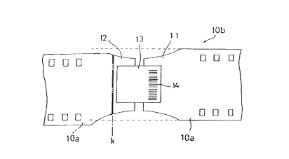
As shown in Figs. 2 and 3, the reel 1 has, wound thereon, developed
photographic film 10 in a plurality of orders from clients. The term "film 10"
as
used in this specification has two meanings. One meaning is short developed
photographic films l0a included in the orders from clients. The other meaning
25 is a long photographic film lOb formed by successively connecting the rear
end
11 of each short developed film l0a in one order to the forward end 12 of
another short developed film l0a with a splicing tape 13 which is one example
of joining materials (see Fig. 4). The long film lOb may be cut order by order
again prior to an exposing and printing process, as necessary. The short films
_g_
CA2169007
made by cutting the long film lOb are also referred to herein as short films
10a.
As shown in Fig. 5, the long film lOb has a leader 15, which itself is well
known, connected to the forward end thereof.
A dancer 5 is disposed adjacent a support axis of the reel 1 for eliminating a
slack of photographic film 10. A film transport device 40 extends from the
reel
1 toward the image information reading unit 20 and exposing and printing unit
30, which are examples of exposure processing units, for transporting the
photographic film 10, more particularly the long film lOb, wound on the reel
1.
The film transport device 40 includes a first transport portion 40a and a
second transport portion 40b. The first transport portion 40a includes a first
drive roller 42 driven by a pulse motor 41, two idle rollers 43 in contact
with
the first drive roller 42, a second drive roller 45 driven by a DC motor 44,
an
idle roller 46 in contact with the second drive roller 45, a direction
changing
idle roller 47, and a pair of idle roller 48 in contact with each other, for
transporting
i5 the photographic film 10 toward the image information reading unit 20.
A film cutting device 6 described in detail later is disposed on the transport
line of the first transport portion 40a. The film cutting device 6 cuts the
long
film lOb into short films l0a each corresponding to one order, and cuts off
part
of the film.
2o The second transport portion 40b of the transport device 40 transports the
short films l0a from the film cutting device 6 to the image information
reading
unit 20. The second transport portion 40b includes a third drive roller 49a,
an
idle roller 49b, and a pair of idle rollers 49c.
A plurality of sensors are arranged along the transport line of the transport
25 device 40. These sensors include, for example, a film sensor 81 disposed
upstream of the first drive roller 42 for detecting the photographic film 10,
and
an end sensor 82 disposed downstream of the first drive roller 42 for
detecting
splice regions of the photographic film 10 joined with the splicing tape 13,
i.e.
for detecting rear ends 11, forward ends 12 or splicing tapes 13. Each of
these
-9-
~A~j ~9~0~
sensors 81 and 82 is formed of a light emitter and a light receiver.
Downstream of the end sensor 82 and upstream of the film cutting device 6
is an image frame distinguishing device 83 which is one example of film
propriety
distinguishing devices for determining whether or not the photographic film 10
s in each order is fit for processing by the exposing and printing unit 30.
The
image frame distinguishing device 83 includes two image frame sensors 83a
and 83b each formed of a light emitter and a light receiver, for detecting
image
frames on the photographic film 10 based on the quantities of light received
after being transmitted through the film 10, and determining lengths of the
io respective image frames on the film 10. Specifically, the image frame
distinguishing device 83, based on frame edge detection signals, measures
longitudinal and transverse dimensions of the image frames in each order to
determine whether the image frames are full size, panorama size or half size.
A discharge device 7 is disposed downstream of the film cutting device 6 for
is removing film portions adjacent the leader 15 and splicing tapes 13 cut by
the
cutting device 6 from the transport line.
The discharge device 7 includes a trash box 50 disposed below the transport
line, a pivotable guide 50a defining a slit for allowing passage of the film,
and a
solenoid, not shown, for driving the guide 50a. The guide 50a is movable
2o between a posture extending along the transport line, as shown in solid
lines in
Fig. 2, for guiding the film 10, and a posture crossing the transport line, as
shown in phantom lines, for guiding cut film fragments into the trash box 50.
As shown in Fig. 6, the trash box 50 substantially is a rectangular
parallelepiped
with an open top. Thus, a discharge passage 51 of rectangular cross section is
2s formed below the transport line. The discharge passage 51 has a width, as
seen
in the moving direction of the leader 15, corresponding to or slightly larger
than
the width of the leader 15, so that the leader 15 in descent may remain
substantially
in the same posture.
The leader 15 shown in Fig. 5 has a larger width than the film 10. The
-10-
~~21 E~0~7
above is applicable also where a leader having the same width as the film 10
is
used.
A partition 52 is formed in an intermediate position of the discharge passage
51 for allowing passage of small fragments of the film 10 cut from adjacent
the
s splicing tapes 13 but prohibiting passage of the leader 15.
The partition 52 is in the form of a plate extending parallel to the film
transport line and mounted in vertical posture right under a transversely
middle
position of the transport line. As shown in Fig. 6, the partition 52 defines a
downwardly curved upper edge for contacting the leader 15. The curved edge
io has a lowermost point disposed adjacent an opening 53 described hereunder,
to
guide the leader 15 smoothly.
The opening 53 is formed directly above the partition 52 for passing the
leader 15.
The trash box 50 is vertically divided into two parts in a position slightly
is above the opening 53, the lower part being detachably attached to the upper
part. This construction facilitates disposal of the film fragments collected
in the
lower part.
A loop tank 8 is disposed downstream of the discharge device 7. The loop
tank 8 defines a loop storing space 8a for storing the photographic film 10 in
20 loop form. An open/close loop guide 8b is disposed in an opening of the
loop
tank 8, which is driven by a DC motor not shown.
Downstream of the loop tank 8 and second drive roller 45 is a forward end
sensor 84 including a light emitter and a light receiver for detecting the
forward
end of the photographic film 10. Downstream of the forward end sensor 84 is a
25 transport line branching device 90 acting as a process averting device for
passing,
without being processed by the image information reading unit 20 and exposing
and printing unit 30, photographic film 10 in each order determined unfit by
the
image frame distinguishing device 83.
The transport line branching device 90 branches the photographic film 10 in
-11-
vc ~y~ ~~ ~~ ~~~ 07
each order determined unfit, off the second transport portion 40a of the
transport
device 40. As shown in detail in Figs. 7A and 7B, the branching device 90
includes a through passage 91 acting as a branch line extending obliquely
upward through a frame disposed on the transport line of the transport device
s 40, a line switching element 93 pivotably attached to an axis 92 inside the
through passage 91, and a solenoid 94 for driving the line switching element
93.
A fourth drive roller 96 driven by a DC motor 95 is disposed adjacent a
terminal
end of the through passage 91. The axis 92 supports an idle roller 97 in
contact
with the fourth drive roller 96. Thus, the photographic film 10 entering the
io through passage 91 is forcibly transported. A first rear end sensor 85 and
a
second rear end sensor 86 are arranged along the transport line of the
transport
device 40 upstream and downstream of the through passage 91, respectively, for
detecting the rear end of the photographic film 10.
The image information reading unit 20 and exposing and printing unit 30 are
is arranged in the stated order downstream of the transport line branching
device
90. The image information reading unit 20 and exposing and printing unit 30
both have known constructions. The image information reading unit 20 includes
a lamp 21, a mirror barrel 22 and an image pickup 23. The exposing and
printing unit 30 includes an exposure lamp 31, adjusting filters 32, a minor
2o barrel 33, optics 34 and a shutter 35 for enlarging and printing the images
of the
photographic film 10 on printing paper 9.
The film cutting device 6 includes a main cutter 60 and an auxiliary cutter
70. The main cutter 60 cuts the long film lOb along a transverse cutting line
"k", as shown in Fig. 8A, at the forward end of each succeeding short film
10a,
2s so that the splicing tape 13 remains on the rear end 11 of the preceding
short
film 10a. The auxiliary cutter 70 cuts, along arcuate cutting lines "m" as
shown
in Fig. 8B, the rear end 11 of the preceding film l0a and the forward end 12
of
the succeeding film l0a at opposite lateral regions across the splicing tape
13.
An order in which the main cutter 60 and auxiliary cutter 70 are operated to
cut
-12-
_ CAS 1 ~9~r07
the long film lOb may be determined according to limitations such as an
arrangement of the cutters. The present invention is not limited to a
particular
order. However, in the example shown in Figs. 8A and 8B, the auxiliary cutter
70 is operated first to cut off the opposite sides of the film, and then the
main
cutter 60 is operated to cut transversely of the film.
As schematically shown in Fig. 9, the main cutter 60 includes a vertically
movable upper blade 61 extending across the film transport line, and a lower
blade 62 fixed on the transport line. When the upper blade 61 is lowered to
the
lower blade 62, the film is cut at the cutting line "k" shown in Fig. 8A.
Further,
the leader 15 is cut off at cutting line "j" shown in Fig. 5. The auxiliary
cutter
70 includes a pair of vertically movable upper blades 71a and 71b arranged at
opposite sides of the film transport line, and a pair of right and left lower
blades
72a and 72b fixed on the transport line. When the upper blades 71a and 71b are
lowered to the lower blades 72a and 72b, respectively, the opposite sides of
the
i5 film are cut arcuately at the cutting lines "m" shown in Fig. 8B. As shown
in
Fig. 8A, the short films l0a may be interconnected such that the rear end 11
of
the preceding film l0a and the forward end 12 of the succeeding film l0a are
staggered sideways (a maximum amount of displacement may be guessed from
experience). The arcuate cuts noted above are made to such an extent that the
2o width of the forward end 12 remaining attached to the splicing tape 13
after the
cutting operations of the main cutter 60 and auxiliary cutter 70 is contained
within the width of the preceding film 10a.
The auxiliary cutter 70 has a specific construction as shown in Figs. l0A and
lOB. The upper blades 71a and 71b are secured to a lift block 73 fixed to a
lift
25 pin 74. The lift pin 74 has an upper cam follower 75 and a lower cam
follower
76 spaced from each other. An eccentric cam 77 is disposed in a space between
the upper cam follower 75 and lower cam follower 76 to be rotatable by a motor
78. A frame 79 is provided for supporting the lift block 73 and guiding the
lift
pin 74. The eccentric cam 77 in rotation contacts the upper cam follower 75
-13-
~~2169~
and/or the lower cam follower 76 to raise the lift pin 74, and thus the upper
blades 71a and ?lb. With a further rotation of the eccentric cam 77, the lift
pin
74 is lowered and so are the upper blades ?la and 71b. By suitably selecting a
shape of the eccentric cam 77, one rotation of the motor 78 produces a
vertically
s reciprocating motion of the upper blades 71a and 71b. Such a raising and
lowering mechanism is known in the art and will not particularly be described
herein.
The main cutter 60 has substantially the same construction as the auxiliary
cutter 70, and will not be described. Naturally, other types of raising and
io lowering mechanism may be employed, and the present invention is not
limited
to a particular type.
Where the main cutter 60 and auxiliary cutter 70 are integrated, the lower
blades 62 and 72 may be formed together, and the shape of the eccentric cam
may be devised to share the motor 78. Such integration will contribute to
15 reduced cost.
As shown in Fig. 8A, the splicing tape 13 is allowed to remain on each
preceding short film l0a when the cutting device 6 is operated to cut the long
film lOb into short films l0a for respective orders. The splicing tape 13
includes
ID information, preferably in the form of a bar code 14, printed thereon for
2o identifying the preceding film 10a. The splicing tape 13 is retained in
order to
use this information in subsequent processing of this film 10a.
Operations of this automatic exposing and printing apparatus will be
described next. First, the reel 1 on which long developed photographic film
lOb
is wound is set in place, and the forward end of the long film lOb or the
leader
2s 15 attached to the forward end is passed around the dancer 5 and inserted
into
the film transport device 40.
When the film sensor 81 detects the long film lOb, the pulse motor 41 is
operated to rotate the first drive roller 42 to transport the long film lOb,
and the
solenoid of the discharge device 7 is operated to swing the guide 50a to the
state
-14-
~~~~ X90
shown in phantom lines in Fig. 2.
When, in this state, the end sensor 82 detects a joint in the long film lOb,
the
main cutter 60 is operated to cut off unwanted parts of the long film lOb such
as
the forward end and the leader 15. At this time, the forward end and the
leader
s 15 of the long film lOb are guided by the guide 50a to extend downward.
Thus,
the unwanted, cut parts fall into the trash box 50. Subsequently, the guide
50a
is returned to the state shown in solid lines in Fig. 2. The long film lOb
with
the forward end cut off advances through the slit formed in the guide 50a to
the
second drive roller 45. The second drive roller 45 advances the long film lOb
io further on to the forward end sensor 84.
When the forward end sensor 84 detects the forward end of the long film
lOb, the DC motor 44 is stopped to stop the second drive roller 45. The loop
guide 8b of the loop tank 8 is swung to the position shown in a phantom line
in
Fig. 2 to open the loop tank 8.
is In this state, the first drive roller 42 continues rotating to transport
the long
film lOb. Consequently, as shown in Fig. 3, the long film lOb slacks downward
to form a loop inside the loop storing space 8a. When the end sensor 82
detects
a next joint, the first drive roller 42 is stopped rotating. Then, the
auxiliary
cutter 70 is operated to cut off opposite film portions laterally of the
splicing
2o tape 13 at the cutting lines "m" in Fig. 8B. After rotating the first drive
roller
42 by a predetermined amount, the main cutter 60 is operated to cut the film
at
the cutting line "k" in Fig. 8A. This results in the photographic film l0a in
one
order cut with the corresponding splicing tape 13 remaining attached thereto.
The bar code 14 printed on the splicing tape 13 is read by a bar cord reading
2s sensor 87 disposed in a suitable position on the transport line, to be used
in
subsequent film processing.
The second drive roller 45 is rotated again to transport the photographic film
l0a in this one order. When the rear end of this film l0a moves past the
forward end sensor 84, the loop guide 8b is swung back to the position to
close
-15-
CA2~~~~9~0
the loop tank 8.
The photographic film 10a in one order cut off the long film lOb has already
been checked by the image frame distinguishing device 83 whether or not the
film l0a is fit for processing by the exposing and printing unit 30. That is,
it
s has been determined whether the image frames on this film l0a are full size
or
panorama size suited to the exposing and printing unit 30, or half size not
suited
thereto. If the frames are the sizes suited to the exposing and printing unit
30,
the film 10a is transported to the image information reading unit 20 at the
next
stage. Necessary information is read and shown on the display 2. Subsequently,
to the exposing and printing unit 30 prints the image frames on the printing
paper
9. At a point of time the rear end of the photographic film l0a passes the
second rear end sensor 86, the first drive roller 42 is driven again to repeat
the
same operation.
When the image frames on the photographic film l0a are the size not suited
is to the exposing and printing unit 30, the solenoid 94 is operated to drive
the line
switching element 93. The line switching element 93 guides the film l0a into
the through passage 91. The DC motor 95 is operated to rotate the fourth drive
roller 96 to discharge the film l0a from the transport line. At a point of
time
the rear end of the film l0a passes the first rear end sensor 85, the first
drive
2o roller 42 is driven to repeat the same operation.
Other embodiments will be described hereinafter.
The foregoing embodiment includes the image information reading unit 20
and exposing and printing unit 30 as examples of exposure processing units.
These exposure processing units include all processing units needed to expose
2s and print the images of photographic film on printing paper.
Only the image frame distinguishing device 83 has been described as an
example of film propriety distinguishing devices. In extreme cases of over-
exposure or under-exposure, for example, film need not be transmitted to the
image information reading unit 20 or exposing and printing unit 30. A device
-16-
C~,21 ~~~07
may be provided for distinguishing this type of film, and such a device also
is
included in the film propriety distinguishing devices.
Further, the transport line branching device 90 is shown as an example of
process averting devices. Another example is a device for taking an
appropriate
s measure to omit the exposing and printing process for photographic film 10
unsuited to the exposing and printing unit 30.
The image frame distinguishing device 83 may include notch sensors for
detecting notches cut in lateral edges of photographic film 10, in place of
the
image frame sensors 83a and 83b described in the foregoing embodiment. That
io is, the image frame distinguishing device 83, based on detection signals
from
the notch sensors, may measure longitudinal dimensions of image frames in
each order to determine whether the image frames are full size, panorama size
or half size.
The foregoing embodiment includes the transport line branching device 90
is acting exclusively as a process averting device. However, the discharge
device
50 for removing unwanted parts of film from the transport line may be used
also as the process averting device. That is, photographic film 10 determined
by the image frame distinguishing device 83 to be unfit may be dropped into
the
trash box 50 by operating the guide 50a. In this case, the photographic film
10
2o and unwanted parts of the film may be sorted for collection.
In the foregoing embodiment, the discharge passage 51 includes the partition
52 formed of a single plate for deflecting the leader 15. The partition may
have
various shapes such as a bar shape, or a lattice shape for allowing passage of
film fragments cut from regions adjacent the splicing tape 13.
2s In the foregoing embodiment, the opening 53 of the discharge passage 51
has a lower edge at equal height to the upper edge of the partition 52 at the
end
adjacent the opening 53. As shown in Fig. 11, the upper edge of the partition
52 at the end adjacent the opening 53 may be at a higher level than the lower
edge of the opening 53 of the discharge passage 51. Then, the leader 15 may be
-17-
- ~'~ .?_~~ 69001
discharged smoothly without the forward end thereof being caught by the lower
edge of the opening 53.
In the foregoing embodiment, the partition 52 is mounted in vertical posture
right under a transversely middle position of the film transport line (on the
s dot-and-dash line in Fig. 12). However, as shown in Fig. 12, the partition
52
may be displaced sideways by a distance W from the dot-and-dash line position.
With this construction, when film fragments cut fmm regions adjacent the
splicing
tape 13 fall in horizontal posture and collide with the upper edge of the
partition
52, the film fragments rest asymmetrically thereon. As a result, the film
fragments
to quickly become tilted and fall down the discharge passage 51. That is, the
film
fragments cut from regions adjacent the splicing tape 13 fall smoothly past
the
partition 51.
~s
-18-