Note: Descriptions are shown in the official language in which they were submitted.
Wo 95/04901 PcTIusg4/o8s94
GS
1 -
OUTDOO~ COOKING DEVICE
BACKGROUND OF THE INVENTION
1. Field of the Invention
The present invention relates to outdoor cooking devices and more
5 particularly, to outdoor cooking devices such as an outdoor barbeque oven.
2. Desc.i~lion of Related Art
A popular form of food preparation during warm weather is the outdoor
barbeque. Typically, food is pl~a,ed by cooking it on a grill of an outdoor
barbeque oven. Such barbeque ovens are usually heated with an ignitable fuel
source such as charcoal, propane gas or a liquid fuel. Such cooking arrangementstypically include a metal cover which fits over the cooking surface. In use, such
covers become very hot which makes them difficult to handle and pose a burning
hazard. In the case of charcoal grills, particularly large charcoal grills, it is
especially difficult to obtain uniform heating across the grill surface unless a large
amount of charcoal is used to cover the entire area under the grill. However,
when a large amount of cha,coal is used the grill can become too hot for cooking.
As a result, it is nece~ ry to wait until the fire dies down thus wasting energy and
cooking time.
There is a need in the art for an outdoor cooking device which provides
more unir()llll telllpe,dtures on the cooking surface, prevents the outer surface of
the device from becoming too hot and provides more economical fuel
con.~-lmption.
-
WO 95/04901 2 t ~ ~ ~ 6 5 PCT/US94/0899~
SVl\~IMARY OF THE INVENTION
The invention provides an outdoor cooking device which includPs a base, a
cover and a multilayer heat in~ ting composite. The base includes a food
cooking surface and means for ~uppolling an ignitable heat source for heating the
cooking surface. The cover is supported on the base and Pnçloses an open space
facing the cooking sllrf~ce. The composite is on an inside surface of the cover
and is effective for distributing heat more unirollllly over the cooking surface and
reduçin~ transfer of heat to an outer surface of the cover. The composite incl~ldes
at least two layers of metal foil and at least one of the layers has a plurality of
projections thereon in point contact with an ~dj~çnt layer of the metal foil so as to
provide a plurality of air spaces therebetween.
According to various features of the composite, the composite can include
three layers of metal foil, four layers of metal foil or more than four layers of
metal foil. At least one of the layers of metal foil preferably includes a pattern of
embos~mPnt~ therein se~aldting the layers to allow thermal convection in spaces
therebetween and provide thermal conductiQn at spaced-apart points of contact
between the embo~mPnt~ and an adjacent one of the layers. Although each of the
layers of metal foil can include a pattern of embos~mPnts, it is plc~felled that one
of the layers of the metal foil in contact with the inside surface of the cover is an
outermost layer which is flat. The layers of metal foil can be of any suitable
metal such as ~lllminllm or an ~lllmin~lm alloy. Preferably, the layers of metal foil
are not met~lhlrgically bonded together and the composite consists entirely of
~lllmimlm foil.
According to one aspect of the invention, the composite subst~nti~lly covers
all of the inside surface of the cover. For in~t~nce, the composite can include a
plurality of discrete sections with one of the sections being located on a center of
the inside surface of the cover and another one of the sections being located
adjacent a lower edge of the inside surface of the cover. The composite can
include a flat metal foil ~tt~ched to the inside surface of the cover by any suitable
means such as plt;S~ule sensitive adhesive or the composite can be ~tt~hed by a
mech~ni~l connection such as bolts, screws, etc. A second multilayered heat
' wogsl049ol 2 1 6~65 ~usg4108994
insn1~ting composite can be provided on the inner surface of the base and the
second composite can be ~tt~hP-d to the inner surface of the base in the same
manner that the first composite is ~tt~hed to the cover. The base can include a
charcoal ~uppo1Ling grate located above a bottom wall of the base and the secondcomposite can extend complete around the inner surface of the base and extend
between the ch~coal ~u~olLing grate and an upper edge of the base.
The base and cover can each be of a single layer of metal such as a
porcelain coated sheet of steel. The cover can include one or more openings
th~rell11ough for venting of the cooking device in which case the composite
inc1udçs holes the1~Lhrough in fluid commllnir~tion with the openings in the cover.
The ignitable heat source can comprise charcoal briquettes which can be supported
on a suitable grate in the base or the ignitable heat source can comprise another
type of fuel such as propane gas distributed beneath the cooking surface by a
suitable gas distributing burner arrangement.
BRIEF DESCRIPIION OF TEIE DRAWINGS
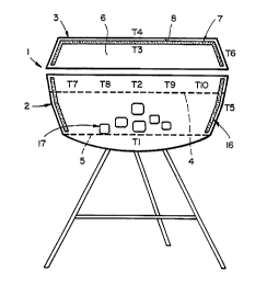
Figure l shows an outdoor cooking device in accordance with the
invenhon;
Figure 2 shows a multilayer heat in~ ting composite in accordance with
the invention;
Figure 3 shows a comparison of average te111p~1dtures measured by
thermocouples l-5 in Figure l in a cooking device in accordance with the
invention compared to a cooking device without the mulhlayer heat in~ ting
composite according to the invenhion;
Figure 4 shows a co1~pa~ ;~on of average temperatures across the cooking
surface measured by thermocouples 7, 8, 2, 9 and l0 in Figure l in a cooking
device in accordance with the invenhon compared to a cooking device without the
multilayer heat in~u1~ting composite according to the invenhion;
Figure 5 shows a co~ on of le1~1pt;1dt-lres measured by thermocouple 1
in Figure l in a cooking device in accordance with the invenhion cG111~cd to a
cooking device without the multilayer heat in$111~ting composite according to the
mventlon;
WO 95/04901 2 1 G ~ 2 6 5 PCT/US94/0~
Figure 6 shows a co,-~p~ on of te-,-pcldtures measured by thermocouple 2
in Figure 1 in a cooking device in accordance with the invention co---l,~cd to acooking device without the multilayer heat in~ ting composite according to the
invention;
Pigure 7 shows a col,lpalison of t~ alUl`~S measured by thermocouple 3
in Figure 1 in a cooking device in accoldallce with the invention co~ ared to a
cooking device without the multilayer heat in~ ting composite according to the
mventlon;
Figure 8 shows a co-"~ on of le-..pç~tnres measured by thermocouple 4
in Figure 1 in a cooking device in accordallce with the invention co"~d to a
cooking device without the multilayer heat inclll~fing composite according to the
inventlon;
Figure 9 shows a co~p~ison of te",l)eldtures measured by thermocouple 7
in Figure 1 in a cooking device in accoLdance with the invention compared to a
cooking device without the multilayer heat in~ tin~ composite according to the
invention;
Figure 10 shows a co",~alison of ~e",peldLu~ s measured by thermocouple
8 in Figure 1 in a cooking device in accordance with the invention co,-.~ d to acooking device without the multilayer heat in~ ting composite according to the
invention;
Figure 11 shows a co",~alison of lelllpeld~ures measured by thermocouple
9 in Figure 1 in a cooking device in accor~ance with the invention coll,~a~ed to a
cooking device without the mulhlayer heat in.~tll~ting composite according to the
mvenhon;
Figure 12 shows a co"lpalison of tempeldtules measured by thermocouple
10 in Figure 1 in a cooking device in accordallce with the invenhon compared to a
cooking device without the mulhilayer heat in~ ting composite according to the
invenhion;
Figure 13 shows a co~p~ on of differences in temperatures measured by
thermocouples 3 and 4 in Figure 1 in a cooking device in accorclance with the
Wo 95/04901 PCT/US94/08994
2169265
invention cGIllpa~ed to a cooking device without the multilayer heat inml~ting
composite according to the invention; and
Figure 14 shows a co",pa,ison of temp~ s measured by thermocouple
5 in Figure 1 in a cooking device in accordance with the invention cG~Ilpa ed to a
S cooking device without the multilayer heat ins~ ting co~"po~ile according to the
invention.
DETAILED DESCRIPTION OF THE INVENTION
The invention provides an outdoor cooking device which inrl~des a base a
cover and a multilayer heat in~ul~ting composite. The base includes a food
cooking surface and a means for ~u~olLing an ignitable heat source for heating
the cooking surface. The cover is ~p~o~Led on the base and encloses an open
space facing the cooking s--rf~e. The multilayer heat in~ ting composite
includes a plurality of layers of metal foil for distributing heat more uniformly
over the cooking surface and redllcing transfer of heat to an outer surface of the
cover.
Figure 1 shows an outdoor cooking device 1 in accordance with the
invention. The device 1 includes a base 2 and cover 3. The base 2 incl~des a
food cooking surface 4 such as a wire grill and means 5 such as a grate for
~u~Glling an ignitable heat source for heating the cooking surface 4. The cover 3
can be pivotally suppolled on the base 2 and/or removable th~lerlolll and the
cover 3 includes an open space 6 facing the cooking surface 4. A multilayer heatin~ul~ting composite 7 is provided on an inside surface 8 of the cover 3. As
shown in Figure 2 the composite 7 includçs at least two layers 9 of metal foil and
at least one of the layers has a plurality of projections 10 thereon in point contact
with an adjacent layer of the metal foil so as to provide a plurality of air spaces 11
therebetween. One of the layers 12 can be flat and a layer of adhesive 13 such as
Ssule sensitive adhesive can be provided on the flat layer 12 to f~cili~tç
~tt~hment of the composite 7 to the inside surface 8 of the cover 3. An edge 14
of the composite 7 can be secured together by any suitable means such as staples15. Alternatively the edge 14 can be pelrol~led to interengage the various layers
Wo 95/04901 2 1 G ~ ~ 6 5 PCT/US94/0899~
of metal foil or one layer of foil can wrap around the edges of the lG~ initlp foil
layers.
Each of the layers 9 of metal foil can be provided with a pattern of
emboccmPntc. To avoid nesting of the emboccmPntc, one sheet can have a pattern
of emboccm~ntc oriente~ at 90 and the ~ ent sheet can have a pattern of
emboccmPntc orirnt~ at 22. That is, the emboscm~ntc can have the same
spacing and heights but by orienting the pattern of emboc~mrntc in dirrGrei~t
directions it is possible to stack the layers of metal foil such that the embo~ n
do not coincide and nest in each other. The size and sp~ring of the emboscmçntc
can be adjusted depending on the thicknesc of the metal foil. Typically, the
heights of the embo~cmentc will be smaller for thicker metal foils and higher for
thinner metal foils. As an example, a two mil ~lllmin~m foil can be embossed
with a spacing of 0.200 inch between emboscm~ntc and with a 0.035 inch height
of emboscmentc
The composite 7 can include as few as two layers of foil but preferably
includes at least three layers or more. To f~rilit~te ~tt~rhment of the composite to
the inside of the cover, the composite can include an outermost flat metal foil
which has a layer of pressure sensitive adhesive thereon. Depending on the shapeof the cover, it may be nP~ec~ry to provide the composite 7 in more than one
section with or without shaping means such as slits, perforations, cut-outs, etc.
For inct~nre, in the arrangement shown in Figure 1, the composite 7 can include a
flat center section ~tt~rhed to the center of the inside surface of the cover and one
or more additional circumferentially ç~rtçn~ling sections can be provided ~ cçntthe lower edge of the cover. The center section of the composite can be circularin shape and include a plurality of radially PYten-ling slits ~ytPnrling inwardly from
the outer edge thereof to f~rilit~te shaping the composite such that the outer edge
bends downwardly along the sloped outer wall of the cover. The cover can
include one or more vent openings and the composite 7 can include holes
theret~,rough in fluid communic~tion with the vent openings.
As shown in Figure 1, the cooking device 1 can also include a second
composite 16 located on the inner wall of the base 2. The second composite 16 is
WO 9S/04901 2 1 6 9 2 6 5 PCTIUS94/08994
.
-- 7 -
idPnti~l in construction to the composite 7. Thus, the second composite 16
surrounds charcoal briquettes 17 ~,uppolled on the grate 5 and the second
composite 16 eYtPn~s between the grate 5 and an upper edge of the base 2. Also,
the second composite 16 preferably eYt~n~ls completely around the inner surface of
the base 2.
The composite according to the invention surprisingly and unexpectedly
reduces the transfer of heat between the interior of the cooking device 2 to an
outer surface thereof. In ~d-lition, the composite is effective in distributing heat
more uniformly across the cooking surface 4. Figures 3-14 show results of tests
carried out in a cooking device of the type shown in Figure 1 with and without the
composite 7, 16 according to the invention. The composite used in the inml~t~d
grill inc]l-dP~l four aluminum metal foil layers, three of which were embossed and
one of which was a flat layer adhesively bonded to the inside s--rf~Ps of the cover
and base. Each of the aluminum foils had a thi~knPs~ of two mils.
1~ Thermocouples Tl-T10 were located at the positions shown in Figure 1. The tests
were carried out by using two idPntic~l barbeque grills, one of which was
incul~ted as shown in Figure 1 and the other of which was -nincul~t_d
During the tests, cha,coal briquettes were arranged in symmPtric~l layers of
16-9-4-1 in both griIls and the charcoal briquettes were taken from the same
container. The top and bottom vents of both grills were fully opened to ensure
optimum draft. The therrnocouple leads were connP~ted to the corresponding
terminals of a ~e."~eldLule mto~nring device. Equal amounts of lighter fluid were
applied to both piles of charcoal and the charcoal was ignited after the charcoal
was allowed to absorb the lighter fluid for two minut~ps When the chalcoal in
both grills achieved a uniform white/gray appe~r~nce, the cooking grills and
covers were placed on the base of each grill. Te,.~p~ t~l,e re~-ling~ were
monitored every 10 minutes and the measurements are shown in Figures 3-14.
Surprisingly and unexpectedly, the in~ t~d grill provided a much higher
temperature across the cooking grill surface than the uninsul~t~1 griIl. Thus, the
incul~t~ grill according to the invention can utilize the heat from a given quantity
of ch~;oal in a much more efficient manner than an l-nin~ul~ted grill.
WO g5/04901 2 ~ 6 5 PCT/US94/0~4
Figure 3 shows an average of the temperatures measured by thermocouples
Tl-T5. In particular, the results for the in~ tP~i grill in acco~ ce with the
invention are shown behind the co.l-paldLive results for an unin~nl~ted grill.
Figure 4 shows average te...L)~ldtures of the cooking grill surface as
measured by thermocouples T7, T8, T2, T9 and T10. In particular, the results forthe in~nl~tPd grill in accor~allce with the invention are shown behind the
co",p~ e results for an unin~ tPd grill.
Figure 5 shows measured le,llpe~,.lll.es for thermocouple Tl at time
intervals of 10 "~ utes. In particular, the results for an incnl~tPd grill in
accoldallce with the invention are shown behind the comparative results for an
unin~nl~t~d grill.
Figure 6 shows measured tempeldlwc;s for thermocouple T2 at time
intervals of 10 I~;nl~les~ In particular, the results for an inclll~t~d grill inaccol.lallce with the invention are shown behind the conlp~dtive results for an
llninml~t~d grill.
Figure 7 shows measured ~e...r~ tllres for thermocouple T3 at time
intervals of 10 minut~s. In particular, the results for an in~nl~tPA grill in
accordance with the invention are shown behind the col"p~,~tive results for an
Imin~ul~ted grill.
Figure 8 shows measured ~e"lpeldlules for thermocouple T4 at time
intervals of 10 minutPs In particular, the results for an insnl~t~d grill in
accol.lance with the invention are shown behind the co.l-p~dtive results for an
min~ t~d grill.
Figure 9 shows measured te..~eldtures for thermocouple 17 at time
intervals of 10 minutes. In particular, the results for an incnl~tP~ grill in
accordance with the invention are shown behind the comparative results for an
~min~ te~l grill.
Figure 10 shows measured l~lllpeldlul~s for therrnocouple T8 at time
intervals of 10 minutes. In particular, the results for an in~nl~tP~d grill in
accordance with the invention are shown behind the co,n~a,ative results for an
llnin~nl~tP~i grill.
WO 95/04901 2 1 6 ~ 2 6 5 pcTtuss4to8ss4
g
Figure 11 shows measured ~e"ll~r,.,t~-res for thermocouple T9 at time
intervals of 10 ~inu~es In particular, the results for an in~ ted grill in
accordance with the invention are shown behind the col~lp~,Ative results for an
lmin~ul~t.od grill.
Figure 12 shows measured lel,lpe ~tures for thermocouple T10 at time
intervals of 10 Illit~ s. In particular, the results for an inc~ te~ grill in
accordance with the invention are shown behind the co",l.~".l;~re results for anmin~ul~ted grill.
Figure 13 shows differences in lel~pel~tures measured by thermocouples
T3 and T4. In particular, the differences in ~ellll~ l,es between thermocouples
T3 and T4 for an in~ ted grill in acco-d~ulce with the invention are shown behind
the co"lp~dti~re results for an llnin~ ted grill.
Figure 14 shows a co~ on between te",peldtures measured by
thermocouple T5. In particular, as shown in Figure 14 the temperatures recorded
outside the top of the base of a grill ins~ t~ in accordallce with the invention are
much lower than the measured te,--peldLules for the same location in an
unin~ ted grill.
The foregoillg has described the princirles, preferred emborlim~nt~ and
modes of operation of the present invention. However, the invention should not
be construed as being limited to the particular embo-lim~nts discussed. Thus, the
above-described embo~lim~-nt~ should be regarded as illustrative rather than
restrictive, and it should be appreciated that v~ri~tion~ may be made in those
embo-lim~nt~ by wo~kels skilled in the art without departing from the scope of the
present invention as defined by the following claims.