Note: Descriptions are shown in the official language in which they were submitted.
2 1 69320
The present invention relates to a tundish for receiving and
filtering of melts of iron-type metals, comprising an outlet
in the bottom region for discharging the molten metal after
passing through a reversing and/or filtering means.
Such tundishes, which are also known as intermediate vessels
or intermediate ladles, are used as well in the continous
casting as also in the discontinous casting of molten
metals. It is known to treat lten metal, especially steel,
in such tundishes or at least to secure that a major part of
the impurities, especially slag, is removed from the melt or
that such impurities or slags are settled and that they can
easily be removed from the melt thereafter.
A device for filtering metallic melts is known for example
from DE-OS 35 09 113. In this known embodiment two plates
are arranged in flow direction of the molten metal and are
spaced apart from another, wherein the bores of the plates
are offset and a chamber for allaying the flow is provided
between this plates. Hereby it is assumed that the sepa-
ration of impurities of a metallic melt requires some time
and therefore the flow of the melt near the filtering device
should be allayed by reduction of the flow rate, whereby it
is also desired to achieve a diversion of the melt by
displacing the passage bores, which should favour the
settling procedures.
Another embodiment of an intermediate vessel or tundish for
receiving or filtering of molten metal, such as steel, can
be gathered from EP-A 0 376 526, in which a filter element
with nearly vertically directed passing slits is provided,
wherein the molten metal is supplied on one side of this
element and is withdrawn from the intermediate vessel or
tundish on the other side of the filter element. Also with
this embod;m4nt it is aimed to a diversion or reversion of
the flow direction of the melt for favouring the separation
of impurities, whereby further a baffle is provided which
2 1 69320
projects from the surface of the melt for exactly separating
the distinct regions of the tundish. With adequate baffles
in the bottom region it is also possible to achieve an
additional turbulence of the melt.
According to a further known embc~;r^~t of a tundish for
receiving and purifying of a metal melt of US-PS 5 071 107
it is envisaged that for achieving a laminar flow the melt
passes through a baffle, which shows openings in essentially
horizontal direction, whereafter a filter element is pro-
vided around the outlet of the tundish. The essential part
of the filter action should take place within a filter
element which is arranged in essentially vertical direction,
so that the melt passes through essentially horizontally
directed holes or bores in the filter. Unfavourable with
this known embodiment is the fact that it is possible that a
great amount of impurities or slags can accumulate and
solidify in the region directly in front of the filter,
which may lead directly to a clogging of the filter element.
In this case it is necessary to replace the tundish or to
remove the settled and cooled impurities in a time-consuming
manner.
Considering this known prior art the present invention aims
to provide a simple device for filtering-off a high-quality
molten metal by maint~i n; ng a high pouring or casting rate,
whereby at the same time a clogging of the tundish with
solidified slag should be avoided. For solving this problem
the tundish according to the present invention is especially
characterised in that a ceramic filter being removable in a
manner known per se and covering essentially the whole
horizontal section of the tundish is mounted in the tllnAi~h,
which filter extends essentially in horizontal direction and
is provided with openings, which are arranged in an
essentially vertical direction being the flow direction of
the molten metal through the tundish. Because of the fact
that the cer~m;c filter covers essentially the whole
- 2 1 69320
horizontal section of the tundish a sufficiently large
effective flow area for the molten metal is provided, so
that the filtering may be effected in a sufficiently short
time. By using an adequate ceramic filter, which should be
removable and therefore simply replaceable, it was found
that for sufficiently removing the impurities or slag it is
not necessary to divert and allay the flow or to achieve a
l~minar flow in the melt, so that according to the present
invention the filter being arranged essentially in
horizontal direction provides a respective large effective
area. Furthermore, according to the present invention the
filter is provided with openings which are arranged in an
essentially vertical direction corresponding to the flow
direction of the molten metal, so that the introduced melt
can pass through the filter as rapidly as possible only
under the action of gravity. Altogether it is therefore
possible to perform a very rapid filtering and purifying
with the inventive tundish, because it is possible to
renounce a comparatively long time of allaying and diverting
the melt in the tlln~;~h, as this was necessary according to
the prior art. Because of the fact that only the
horizontally arranged filter is arranged in the tundish, it
is at the same time avoided that the solidifying slag can be
deposited on vertical baffles of the tlln~;Rh and that
thereby the total volume of the tlln~;~h is drastically
reduced.
For avoiding that by the introduction of the molten metal in
the tlln~;~h slag is directly introduced or pressed into the
filter element, which covers essentially the whole cross-
section of the tlln~;~h, according to a preferred embodiment
the construction is characterised in that in the region of
feeding the molten metal an impact means, especially a
splash core, is arranged in a plane being aligned with the
filter or lying above the filter. Such impact means,
especially a splash core, which is arranged in a plane being
aligned with the filter or lying above the filter, avoids
2 1 69320
thereby a direct impact of the melt on the filter and at the
same time causes a more uniform distribution of the molten
metal on the filter of the tlln~;sh, so that thereafter
nearly the whole filter area can be used for passing and
purifying the molten metal.
In case that the impact means, especially the splash core,
is arranged above the plane of the filter advantageously
essentially the whole horizontal cross-section of the tun-
dish can be covered by the filter and can be used forpassing and purifying of the molten metal. For a careful
charging of the molten metal in the tundish the embodiment
is preferably characterised in that the surface of the
impact means, which is directed to the region of feeding the
molten metal, is arranged above the plane of the filter in a
distance of less than half of the height of the bath of the
lten metal, especially about a third of the height of the
bath. With this arrangement of the impact means it is
possible to largely avoid turbulences when feeding the
molten metal into the molten metal which is already
cont~;ne~ in the tundish and moreover there is provided a
sufficient volume below the impact means and between the
impact means and the filter so that a solidification of the
melt can be avoided in this area.
For a very simple and easy change of the filter according to
a preferred embodiment the tundish is characterised in that
the filter is mounted in an e~changeable frame known per se,
which is arranged in a region of the bottom of the tlln~;~h
or which forms the bottom of the tundish. In case that the
impact means, especially the splash core, is arranged in the
plane of the filter also the impact means can be comprised
in the frame so that by changing the filter the impact means
is changed at the same time. In case that the impact means
is arranged in a plane above the filter, the frame is
provided with the filter element. By arranging the filter
element in an exchangeable frame, which is arranged in the
2 1 69320
region of the bottom of the tundish or which forms the
bottom of the tundish, there is guaranteed a simple and easy
e~change of the filter and also a fast renewed use of the
tlln~;sh. Therefore only a shorter standstill of the tlln~i~h
for exchanging the filter must be taken into account. This
allows essential savings of time compared with embodiments,
in which solified deposits being formed in the region of
baffles or of filter elements being arranged essentially in
vertical direction, as was the case according to the prior
art, had to be removed. Therefore according to the invention
the active time of the tundish is essentially independent of
the active t; m~ of the much che~rer filter.
For being able to use essentially unchanged filter elements
for receiving invariable steel qualities in different scopes
of use and different casting or pouring velocities according
to another preferred embodiment of the invention the cross-
sectional area of the filter is variable by aperture
elements. Such aperture elements, which may be used for
changing the active cross-sectional area of the filter, may
be for example s;mlpy inserted into the frame comprising the
filter, so that by choosing the clear opening of the filter,
which is defined by the aperture elements, respective flow
rates of the melt are adjustable. By suitably choosing the
active passing area of the filter the time of direct contact
of the molten metal in the tundish may be also influenced at
the s~mP time. Almost independently of the desired passing
area, the whole filter area may be completely used, if suc-
cessively different cross-sectional areas of the filter are
opened by the aperture elements.
For avoiding a soli~;f;c~tion of the melt in the filter even
with low flow velocities of the molten metal and therefore a
long holding time thereof, the embodiment is furthermore
preferably characterised in that a heating device is
arranged in the region of the filter and/or the impact
means. Such a heating device, which, in principle, should
- 2169320
-- 6 --
heat only the region of the filter or the filter itself or
the impact means, can thereby built relatively small and
energy saving. A heating device for the impact means may be
especially favourable, if it is arranged above the plane of
the filter.
For nearly completely avoiding an oxidation or other
chemical reactions in the melt after passing through the
filter the embodiment is preferably characterised in that at
least one feed opening for feeding an inert gas into the
purified molten metal is provided under the plane of the
filter.
Particularly when using the inventive tundish in a continous
casting procedure a sufficient output of floating impurities
and of slag may be secured. For achieving this object accor-
ding to the invention the tundish is preferably further
improved in that an outlet or an offset region of the side
wall for withdrawing the slag is provided on a front wall of
the tundish, being opposite to the feeding of the molten
metal.
For maint~;n;ng a sufficient pouring or casting rate and at
the same time totally removing the slag the embodiment is
furthermore preferably characterised in that the pores of
the ceramic filter and/or the whole cross-sectional area of
the filter are selected in such manner that a flow rate of
about 0,01 to 1,0 kg melt/cm2s, especially at least 0,25 kg
melt/cm2s is achievable.
Especially in discontinous casting procedures it may be ne-
cessary to check the permeabilty of the filter after the
complete passing of the molten metal through the filter for
determining, if optionally a replacement of the filter is
necessary before a further casting procedure. A simple check
of the permeability of the filter may be achieved with com-
pressed air, whereby for this purpose according to the
2 1 69320
-- 7 --
invention the embodiment is characterised in that above the
filter a device for feeding compressed air and downstream of
the filter a sensor are mountable on the tundish for
measuring the amount compressed air passing through the
filter after complete removal of the molten metal.
The inventive tundish is further explained on the basis of
examples being shown in the accompanied drawings, in which:
Fig. 1 shows a schematical cross section through an inven-
tive tundish;
Fig. 2 shows a top view of the inventive tundish in the
direction of arrow II to the embodiment of Fig.l, wherein
Fig. 1 is a section according to line I-I of Fig.2; and
Fig.3 is a similar view of a schematical section through an
alternative embodiment of an inventive tundish.
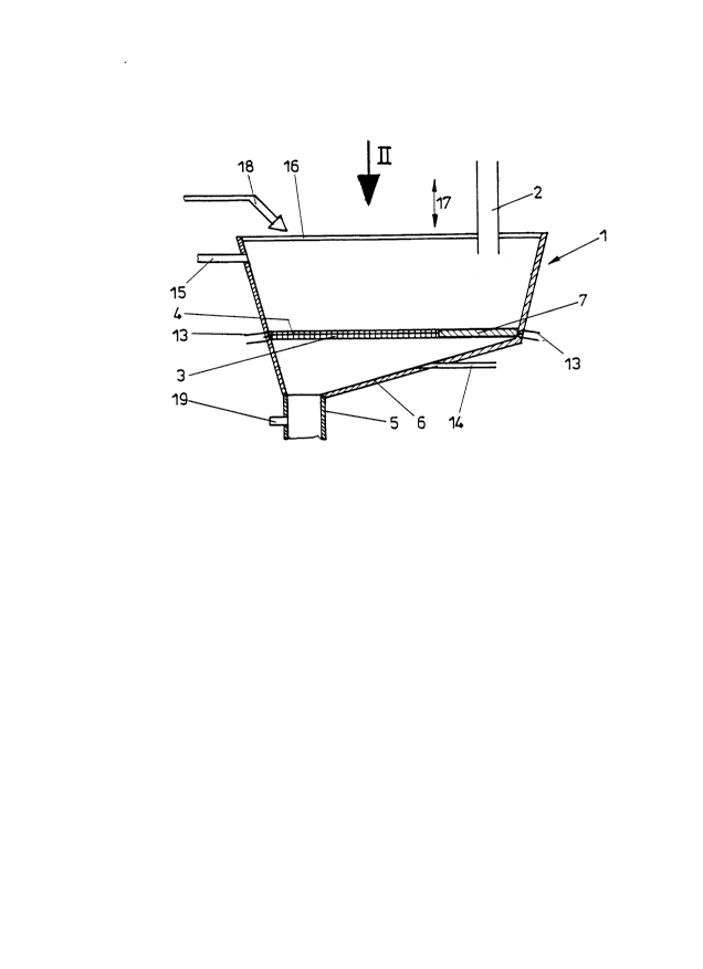
In Figures 1 and 2 a tundish is generally designated with 1,
into which via a feed line 2, especially a refractory pipe
or a refractory casting gutter, molten metal is fed from a
converter or a ladle, which are not shown. After passing of
the lten metal through a removeable filter 3 covering es-
sentially the complete section of the tundish 1 and exten-
ding essentially in horizontal direction and being provided
with openings extending essentially in vertical direction,
which are indicated schematically with 4, the molten metal
is removed through a discharge opening 5 from a funnel-
shaped bottom portion 6 of the tlln~i ~h 1. In a plane being
essentially aligned with the plane of the filter 3 there is
provided an impact means, for example a splash core 7, in
the area of the feed line 2, whereby it is prevented that
lten metal being fed through the feed pipe 2 directly hits
the filter 3 and that the included impurities and slags
directly obstruct the filter 3 in this area.
Simply the filter 3 is mounted in an exchangeable frame 8,
being arranged in the bottom area of the tundish 1 or being
formed as an intermediate bottom, as is schematically indi-
2 1 69320
-- 8 --
cated in Fig. 2. This frame 8 may be additionally providedwith aperture elements 9 and 10, whereby it is possible to
change the effective passing area of the filter in the sense
of double arrows 11 and 12 through simple translational
movement of the aperture elements. By changing the position
of the aperture elements 9 and 10 the effective passing area
of the filter 3 can be adjusted to the needs, for e~ample a
predetermined casting velocity etc..
For avoiding that an excessive cooling and thereby a
solidification of the melt occurs in the area of the filter
3 even with relatively low passing velocities through the
filter 3, whereby the filter 3 is occluded by the soli-
difying melt or solidifying impurities, there is further
provided a heating device 13 in the area of the filter 3, as
is schematically indicated in Fig. 1. This heating device 13
may be only provided in the area of the peripheral wall of
the tundish 1 or can also be coupled with respective heating
devices in the frame 8 comprising the filter 3 to maintain
the desired temperature of the filter 3.
For largely preventing undesired chemical reactions in the
molten metal after passing through the filter 3 there is
additionally provided a feeding opening 14 in the funnel-
shaped bottom portion 6 of the tundish 1 for introducing aninert gas into the purified melt.
Particularly when using the tundish 1 for a continous
casting process it is necessary that accumulating impurities
or slag floating on the molten metal can be removed from the
tnn~; ~h 1, wherefore a discharge opening 15 is provided on a
wall of the tundish 1 being arranged opposite of the feed
line 2. Instead of such a discharge opening 15 there can
also be provided an offset region in the upper portion of
this front wall.
21 69320
For preventing a splashing of the molten metal when intro-
ducing the same into the tundish and for further preventing
an excessive cooling of the molten metal during filtering or
purifying in the tundish 1 there is further provided a
covering or a lid 16, which may be lifted or lowered
according to double arrow 17.
When using the tundish 1 in discontinous casting processes
it might be necessary to check the penetrability of the
filter 3 between individual casting steps to decide if an
exchange of the filter 3 by simple removal of the frame 8 is
necessary. Such a check of the penetrability of the filter 3
can be done with compressed air, wherein after completely
discharging the melt out of the tundish 1 there is injected
compressed air onto the filter 3, as is schematically indi-
cated by the feeding line 18, whereafter the penetrability
of the filter 3 being achieved is detected by a sensor 19
being arranged in the outlet 5.
In the embodiment of Fig. 3 the numerals of the prec~e~;ng
figures have been maint~;n~ for similar elements. In this
embodiment of a tundish 1 an impact means 7 being formed as
a splash core is arranged above the filter 3, wherein the
surface 20 of the impact means 7 facing the feed line 2 for
the molten metal is slightly inclined relative to the
horizontal plane and is arranged at a level, which amounts
to nearly a third of the bath height h of the melt in the
tundish 1. For surely preventing a solidification of the
melt and/or impurities in the area of the impact means 7
there is further provided a heating device 21 in the area of
the impact means 7. With this embodiment for discharging the
slag there is provided an offset portion on the front wall
being opposite to the feed line 2 and being schematically
indicated with 22.