Note: Descriptions are shown in the official language in which they were submitted.
- _ 21 6q480
~ PRO-ED BOLT Cl,~ER
BAC~;GROU?~I)
This irl~,e.l~ion relates to an improved bolt cutting device of the tvpe comprising two jaws
in face to face rPl~ionchip which are pivotally connPcse~ together and each having an end adapted
S for co~nPrtion to a handle. Each of the jaws includes a bevelled cutting edge arranged to rotate
toward and away from each other but not beyond each other in the same plane of rotation.
Operation of the handles causes the jaws to move between open and closed positions thereby
severing the bolt or si-m-ilar elongate member placed therein.
These jaw ~csembliPs are co~ or. with bolt cutting devices wherein each of the jaws is
mounted for rotation around its l~eCLi~e pivot pin or bolt. The pivot bolts are carried on a pair
of straps, one strap on each flat side of the jaw pair. The handles are normally adjustable to perrnit
the jaws to be adjusted to the correct position wherein there is a small clearance between the cutting
edges of the jaws in the closed position.
Bolt cutting devices employing the jaw assemblies described above comprise a relatively
large number of co.l,yone.lL~ which renders the assembly relatively complicated in terms of
~n~nl-f~rttlrin~ and assembly. The improved bolt cutter of the present invention overcomes the
deficiPn~ iP5 of the prior art and provides a bolt cutter of less weight to ease manipulation and less
parts to reduce ~ nre re~u.l~,lle.l~.
An example of a prior bolt cutter is the B. B. Brunosson U.S. Patent No. 3,gO6,631 which
shows a jaw assembly for a bolt cutting device with a single pivot for the jaws.The M. Blanc U. S. Patent No. 3,949,473 discloses a bolt cutter with each jaw pivoted
about its respective pin and mounted between parallel plates.
U. S. Patent No. 4,058,893 to A. Z Boyajian discloses a bolt cutter with one stationary
jaw and a movable jaw actuated through a roller carn arrangement by one of the handles.
The A. ~ Boyajian U. S. Patent No. 4,249,308 discloses another bolt cutter with one
stationary jaw and one movable jaw actuated by a carn roller and cam groove arranged to enable
the carn groove to change its contour and thereby change the m-orh~nic~l advantage.
U. S. Patent No. 4,569,132 to R. A. Hill discloses a compound-action scroll snip which
uses a plurality of washers as a friction reducing means berween pivoting members.
U. S. Patent No. 5,058,272 to G. J. Steube discloses a hydraulically powered bolt and
cable cutter utilizing a scissor mech~nism to actuate the cuttar jaws.
SUI\~MARY
The improved bolt cutter includes a pair of jaws rotatable about a common axis with a pai~
of handles rotatably intercoMected with the jaws. Each handle includes a boss which pivoes about
a cornmon axis to operate the jaws between open and closed positions. .~n ad)ustment means to
21 69480 ~
compensate for wear of the jaws and m~int~in the jaws in substantially face to &ce contact in the
- closed position includes a pair of eccentric bushings disposed between the handle bosses on a
collullon axis. The eccentric bushings include a plurality of protrusions which engage
complementary recesses on the handle bosses to prevent rotation of the eccentric bushings with
respect to the pair of handles when the handles are operated.
An object of the present invention is to provide an improved bolt cutter which minimi7Ps
the number of components to reduce ~ f r~nce reqUi~
Another object of the present invention is to provide an ill,plove~ bolt cutter of less weight
to ease manipulation.
BRIEF DESC~IPrION OF THE DR~WINGS
T,hese and other objects and advantages of the present invention are set forth below and
further made clear by iefer~"~ce to the drawings, wherein:
Figure 1 is an plan view of a prior bolt cutter with each jaw pivoting about its respective
pivot pin.
Figure 2 is an exploded view of the ~i~u~ed bolt cutter of the present invention.
Figure 3 is a plan view of the irnproved bolt cutter of the present invention.
Figure 4 is a cross-sec~ion~l view of the cutter head of Figure 3 taken along lines 1 4.
Figure 5 is a plan view of the underside of the eccentric bushing showing the offset of the
bore with respect to the centPrline of the bushing.
Figure 6 is a cross-sectional view of the eccentric bushing of Figure 5 taken along lines 6-
6.
DESCRIPIION OF THE PRE~:RRED EMBODIMEl~
With reference to Figure 1, a prior bolt cutter, denoted generally by numeral 10, is shown
with the jaws closed. Jaws 12 and 14 are m~in~inPd in opposed relationship by flat plates or straps
16. Jaws 12 and 14 each pivot about their respective pivot bolts 18 and 20 when actuated by
handles 22 and 24. Handles 22 and 24 are pivotally connPcte~ to jaws 12 and 14 by bolts 26 and
28 and are rotatable about pivot pin 30 on a co"~norl pivot axis. Compensation for the wear of
jaws 12 and 14 is by means of adjustrnent bolt 32 in handle 24.
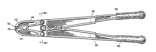
The improved bolt cutter, denoted generally by numeral 40, is shown in Fiaure 2 in an
exploded view. Bolt cutter 40 includes cutter head 42 comprised of left jaw 44 and right jaw 46
which are interchangeable. Jaws 4. and 46 include beveled cutting edges 48 and 5û and are
secured in opposing relationship by jaw bolt ~2 with thread locking compound, such as Loctite
thereon, washers 53 and locking jaw nut 54. Handles 56 and 58 are interchangeable elongate
members of a generally I shaped cross section formed of a suitable material as cast aluminum or
2 1 6 9 4 8 0 PCr~S9~/08s~s
a zinc aluminum alloy. One end of handles 56 and 58 is enlarged with raised lip or StOp 60 forrned
thereon to control the position of handles 56 and 58 in the closed position.
Adjacent stop 60 on each handle 56 and 58 are center pivot hole 62 and handle hole 64.
Handle holes 64 have wear bushings 65 positioned therein and are formed of a suitable wear
S ll,Si~Lal~L material as steel. As seen more clearly in Figures 3 and 4, the rear portion of jaws 44
and 46 have holes 47 drilled thcr~ r.)ugh to receive handle bolts 66 with thread locking compound,
such as Loctite thereon, which are closely received in steel bushing 65 in handle holes 64 to secure
jaws 44 and 46 to handles 56 and 58 with lock nuts 67 and washers 67a. The side of center pivot
hole 62 opposiLe handle StOpS 60 has a plura~ity of hemicphPrica] recesses 68 formed therein and
evenly spaced c~cuu-~.e,lLially. Center pivot bushings 70 have comple.~ taly protrusions 72
formed thereon and an eccentrically drilled hole 74 therein as seen in greater detail in Figures 5
ar d 6.
Center pivot bushings 70 are assembled to handles 56 and 58 25 shown in Figures 2, 3 and
4 _nd secn~red tnerein by bolt 76 which is cross-drilled to receive locking pin 79 after castellated
nut 78 is threaded thereon. In this position, protrusions 72 of center pivot bushings 70 engage
complementar recesses 68 of handles 56 and 58 to prevent rotation of center pivot bushings 70
with respe~ to handles 56 and 58. Cushion grips 80 are installed on the rear portion of handles
56 and 58. During initial assembly and subsequent use, the O~ IU1II poSjtioning of cutting edges
48 and 50 is obtained as follows. With locking pin 79 removed, c~ctp1l~t~d nut 78 is loosened
slightly on bolt 76 to allow center pivot bushings 70 to be moved away from handles 56 and 58
thereby dicPngaging pluL~usions 72 from recesses 68. This allows center pivot bushings 70 to be
rotated which shifts the position of eccentric hole 74 to change the relative position between handles
56 and 58 and thereby adjust the gap between cutting edges 48 and 50. C~ctpll~tpd nut 78 is then
re~ightene~ on bolt 76 and pin 79 reinstalled to prevent rotation of center pivot bushings 70 with
respect to handles 56 and 58 as previously described.
r~e construction of our i~ luv~d bolt cutter and the methods of its applic~tion will be
readily l~ndprstood from the foregoing description and it will be seen we have provided an
improved bolt cutter which minimi~P5 the number of components to reduce ...~ rn~nre
requireme~ts and provide an improved bolt cutter of less weight to ease manipulation.
Fur~hermore, while the i~vention has been shown and described with respect to certain prefe-led
embodiments, i~ is obvious that equivalent alterations and modifications will occur to others skilled
in the art upon the readin~ and undprst~nriing of the specification. The present invention includes
all such e~uiv~lent alterations and modifications, and is limited only by the scope of the appended
claims.