Note: Descriptions are shown in the official language in which they were submitted.
2 1 6~487
CATERING CONTAINER ASSEMBLY
Field of the Invention
The present invention relates generally to a high-strength, modular catelhlg
container assembly. More particularly, the invention relates to a catering tray,catering bowl and a domed cover.
5 B~ck~ound of the Invention
Catering containers have long been employed to store and lldl~rer food prior
to presenting the food to those persons who will consume it. Generally, a caterer
loads the food onto the catering containers after pl~aldlion and stores the containers
until the time at which the food is to be presented to consumers. The caterer then
10 transfers the food from its preparation location to a dining location. To achieve the
best results, it is most desirable to utilize catering containers on which food is easily
loaded, stored, transported, and presented to the consumer while m~int~ining theintegrity of the food.
Most catering containers have easy loading capability since they are flat and
15 circular. The flat tray is then covered with a lid until presentation. However, flat
circular containers can be difficult to store and present since horizontally adjacent
containers abut each other at their circular periphery which leaves a gap, and
therefore, requires additional surface area. Containers with rectangular-shaped
profiles abut against each nicely and elimin~te the gap. But, rectangular-shaped20 containers deviate from the traditional circular catering containers and are less
aesthetically pleasing. Moreover, circular containers are preferable since they have a
greater ability to distribute food in all directions.
Numerous catering containers are often stacked vertically to use less space in
storage. However, this requires a structurally sound container and lid assembly such
25 that the containers on the bottom are not crushed under the weight of those at the top.
The lid must evenly ~ r~r the vertical forces to the container through an
interlocking mech~ni~m between the lid and the container. Additionally, as the
height of the stack increases, the stability of the stack decreases such that those on
top may slide out of ~lignment and fall from the stack. This st~cking stability
30 problem is accentuated when a stack of containers is being m~nll~lly transported by
the caterer.
2 1 69487
The container must also be strong enough to carry its contents. Not only is
the static holding strength important, but the rei.~t~n~e to dynamic torsional and
bending stresses is critical since the container must not become contorted during
h~n-lling and transportation. If the containers are made of metal or ceramic, the issue
of strength becomes secondary. But, many catering containers today are made of less
costly polymers which brings the strength issue to the folcrlolll.
The aesthetical presentment of the contents of the catering container is also
essential. It is most desirable to have a translucent lid such that the contents are
revealed without removing the lid. Not only is translucency essential during
presentation to the consumers, but it is also beneficial to the caterer in that he or she
knows which containers hold which foods. Translucency is easily accomplished
when the lid is a polymer. But, to produce a strong polymeric lid, m~nllfacturers
have resorted to lids with a series of structural ribs. However, these structural ribs
greatly detract from the translucency of the lid, and therefore, the plcscll~bility of
the catering container.
A need therefore exists for an aethPtir~lly pleasing catering container
assembly which overcomes the aforementioned shortcomings associated with
horizontal assembly presentation, vertical st~ ing, and structural stability.
Summary of the Invention
Briefly, the present invention is directed to a new and improved catering
container assembly. More particularly, the present invention relates to a structurally
sound polymer tray and bowl which interlock with a structurally sound polymer
domed cover.
One object of the invention is cateling assembly modularity. This is achieved
by having a hexagonal periphery on the tray and cover to allow for the horizontal
arrangement of multiple catering assemblies on a table. The hexagonal shape allows
for the juxtaposition of all catering assemblies while leaving only a minim~l gap.
The present invention also provides for a mechanism between the cover and
the tray which adequately transmits forces from the cover into the tMy. Indentations
on the lower portion of the cover engage recessed platforms on the tMy for
llal~rellil g the vertical force load from the cover onto the tray. Additionally, the
domed cover has arc shaped cover walls for llal~re,lillg the forces which reduce the
2 1 69487
,
stress concentrations associated with sharp corners. The arc shape also resists lateral
forces directed into the cover walls.
Stiffening elements are also provided in the present invention to strengthen thetray and the cover. Bar ~lirrellel~ join adjacent side walls which extend around the
5 periphery of the tray. Similar structures are present on the domed cover whichelimin~tes the need for structural ribs and, therefore, provides for substantial viewing
clarity into the catering assembly. These ~lirrenillg elements on the tray and cover
resist the torsional and bending stresses which the assembly undergoes during storage
and transportation.
In another embodiment, the tray is replaced by a bowl with a periphery
substantially similar to that of the tray but having a deeper bottom for holdingliquids. Structural elements similar to those existing on the tray are also present in
the bowl. As with the tray, the domed cover is used to cover the contents of thebowl. Furthermore, the surfaces providing depth to the bowl are inwardly arced to
I-all~rer the vertical forces along that surface and resist the force from the food it
contains.
Additionally, a stacking engagement mech~ni~m between the cover of one
catering assembly and the tray or bowl of another catering assembly is also provided.
The st~cking engagement mechanism ",ini",i~es the tendency of stacked catering
assemblies to slide across each other.
The above ~Ullllll;il,~/ of the presented invention is not intended to representeach embodiment, or every aspect of the present invention. This is the purpose of
the figures and detailed description which follow.
Brief Description of the Draw-n~s
Other objects and advantages of the invention will become apl)al~ upon
reading the following detailed description and upon refelellce to the drawings in
which:
FIG. 1 is an isometric view of the tray;
FIG. 2 is a side view of the tray;
FIG. 3 is a top view of the tray;
FIG. 4 is a cross-sectional view of the tray;
FIG. 5 is an isometric view of the domed cover;
2 ~ 69487
-
FIG. 6 is a side view of the domed cover;
FIG. 7 is a top view of the domed cover;
FIG. 8A is a cross-sectional view of the domed cover;
FIG. 8B is a cross-sectional view of the domed cover holding a catering
5 container;
FIG. 9 is an isometric view of the bowl;
FIG. 10 is a side view of the bowl;
FIG. 11 is a top view of the bowl;
FIG. 12 is a cross-sectional view of the bowl;
FIG. 13 is a top view of three tray or bowl catering assemblies which are
adjacent each other; and
FIG. 14 is a side view of two tray-bowl catering assemblies which are
vertically stacked on each other.
While the invention is susceptible to various modifications and alternative
15 forms, certain specific embodiments thereof have been shown by way of example in
the dMwings and will be described in detail. It should be understood, however, that
the intention is not to limit the invention to the particular forms described. On the
contrary, the intention is to cover all modifications, equivalents, and alternatives
falling within the spirit and scope of the invention as defined by the appended claims.
Description of the Preferred E mbo~iment
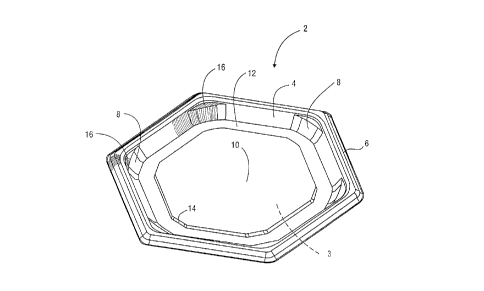
Referring initially to FIG. 1, a catering tray 2 having a hexagonal periphery
is illustrated. The tray 2 has a base 3 and six side walls 4 extending upwardly from
the base 3. A flange 6 is ~thcl~d at an upper portion of the side walls 4 and extends
around the periphery of the tray 2. The side walls 4 are strengthened by bar
25 stiffeners 8 which join adjacent side walls 4. These bar ~lirrellel~ 8 provide
substantial resi.ct~n-~.e to the torsional and bending stresses the tray 2 undergoes while
being handled and transported. Instead of the stresses being concentrated in thecorners of adjacent sides 4, the bar stiffeners 8 assist in evenly llal~re~ g the stress
between adjacent side walls 4 such that the likelihood of failure by deformation or
30 cracking is reduced
A raised food platform 10 is formed on the base 3 of the tray 2 and allows the
food to be aesthetically displayed at the center of the tray 2. The food platform 10
2 1 6q487
shown in FIG. 1 is substantially hexagonal, but it can also be a variety of shapes
such as ovular, circular, or polygonal. A trough 12 is disposed between the foodplatform 10 and the side walls 4 on the base 3 of the tray 2. The trough 12 provides
a region to which the fluids of the food can flow thereby preventing foods from
S sitting in fluid. The normal motions due to h~n~ling and transport shift the fluids
from the foods and into the trough 12 where they are captured. Thus, the food
platform 10 can be subst~nti~lly horizontal or slightly angled in the dowllw~ld
direction toward the trough 12 such that fluids flow to the trough 12 under the force
of gravity. Alternatively, the food platform 10 could have small channels situated
below the surface of the food platform 10 which slope to the trough 12 such that the
fluid flow path would not be hindered by the food congregated on the food platform
10.
The food platform 10 also serves the purpose of providing rigidity when the
tray 2 is loaded with food and being handled. The food platform 10 acts as a
structuMl rib on the base 3 of the tray 2 and resists the tendency of the base 3 to bow
downwardly when holding food. Additionally, the food platform 10 has angled
corners 14 which transfer stresses between adjacent edges of the food platform 10.
The angled corners 14 reduce the stress concentration on the edges of the food
platform 10, and thus, reduce the likelihood of failure.
The tray 2 also includes recessed platforms 16 at the region where adjacent
side walls 4 meet. The recessed platforms 16 provide a surface against which a
portion of a cover which shields the food on the tray 2 abuts. The forces on such a
cover are easily ~ llliL~ed into the tray 2 via the recessed platforms 16. This
reduces the force transferred through the interlocking mech~ni~m between the cover
and the tray which ",ini",i,es the risk that the cover will detach from the tray 2. The
recessed platforms 16 are positioned below and are encompassed within the upper
portion of the side walls 4 such that an abutting structure from the cover is retained
on the recessed platform 16 and prohibited for moving th~lerlolll. The recessed
platforms 16 are shown in FIG. 1 as having a generally triangular shape. However,
the shape of the recessed platforms 16 could be ovular, circular or polygonal.
Furthermore, the recessed platforms 16 could themselves have recesses endowing
~1 69487
them with a three dimensional formation wherein an abutting structure from a cover
would have a substantially similar formation for interlocking.
The recessed platforms 16 also assist in the structural integrity of the tray 2.The recessed platforms 16 llal~rer the forces around the corners of the flange 6 and
5 the upper portions of the side walls 4. This is one reason the recessed platforms 16
have been placed at the corners of the tray 2 in FIG. 1. ~ ",~tively, the recessed
platforms 16 could be moved from the corners to an intermedi~te portion of the side
walls 4. And, the recessed platforms 16 could also be placed lower on the side walls
4 as well to more directly ~-al~rer the force to the base 3 of the tray 2.
FIG. 2 illustrates a side view of the tray 2. This view more accurately shows
the shape of the flange 6 and the general height of the tray 2. Additionally, the
shape of the side walls 4 can be more easily discerned. The height of the flange 6 as
measured from the base 3 which is cont~cting a surface below the tray 2 is fixed for
all sizes of trays 2. For example, tray 2 in FIG. 2 has the same flange height as a
15 tray which is twice as wide or half as wide. This feature facilitates the presentation
of an arrangement of catering trays 2 since no flange of one tray can protrude over
the top of another tray. Although this feature may be beneficial in some applications,
the flanges 6 of different trays 2 can have dirrelelll heights.
FIG. 3 is a top view of the tray 2 wherein the hexagonal periphery is more
20 readily vi~ li7ed.
FIG. 4 is a cross-sectional view of the tray 2. The relative height of the food
platform 10 can be easily seen. Also, the raised platform 10 results in a st~cking
recess 18 which allows the tray 2 to receive a st~rl~ing projection from a cover~tt~ch~cl to another tray which would be directly below the tray 2. Thus, a series of
25 trays can be easily stacked and transported without having the top tray slip from the
stack.
Also in FIG. 4, the profile of the flange 6 is shown in detail. The flange 6
has a profile which allows it to interlock with an interlocking closure of a cover.
Thus, the profile of the flange 6 is chosen according to the interlocking closure
30 available on the cover. Also, the flange 6 has an underside area which allows for
easy gripping of the tray 2. The underside could have a gripping profile whereinfingers are positioned on the profile to ensure that they do not slip from the flange.
21 69487
Generally, the tray 2 is made of polymeric material. One example would be
poly~lylel1e with a thickness in the range from approximately 0.010 inch to
approximately 0.050 inch. Generally, the larger the tray 2, the thicker the material
must be. This tray 2 could be thermoformed from poly~lyrelle sheets. If the tray 2
5 is being designed for extra loading, then thicker sheets of polystyrene could be used.
Additionally, polyethylene or polyl,r~ylene are a few of many other polymers which
can be used as well. And, numerous other suitable methods of m~mlf~cturing such as
blow molding, injection molding, and compression molding could be performed as
well.
In addition to polymers, stronger materials such as reinforced polymers or
metals can be used. This may be applopliate if heavier foods, such as large roasts,
are the desired catered food or if the tray 2 is to be very large. Metal trays may be
advantageous since metal resists higher temperatures and can be reused numerous
times without succumhing to fatigue loading. Al~ lill.llll may be an appropliatechoice since it is ine~ensive and easy to process. The typical sizes of the catering
trays 2 are 12, 16, and 18 inches.
FIG. 5 illustrates a domed cover 30 for covering a catering container, such as
the calelil1g tray 2 shown in FIGS. 1-4. The domed cover 30 has a top 32 and cover
walls 34 extending dowllw~ldly from the top 32. A cover ~lirrel~ing bar 36 is
attach~l to the top 32 and joins adjacent cover walls 34. A turned-down flange 38
extends around the periphery of the domed cover 30 and is attached to a lower
portion of the cover walls 34. The turned-down flange 38 receives a portion of acontainer that releasably engages the domed-cover 30 such as the flange 6 on the tray
2 in FIGS. 1-4. Thus, the domed cover 30 can be detachably attached to a catering
container. A tab 39 is conn~cte~ to the turned-down flange 38 along the periphery of
the tray 2 to assist in the removal of the domed cover 30 from the catering container
to which it is attactlP~l. The details of the turn-down flange 38 are described more in
detail below and shown in detail in FIG. 8A.
A st~r~ing projection 40 is positioned at the top 32 of the domed cover 30.
The stacking projection 40 allows a catering container stacked above the domed cover
30 to fit onto the domed cover 30 to prev~nl such a catering container from sliding.
The st~r~ing recess 18 shown in FIG. 4 of the catering tray 2 is an example of a
21 6q487
\
catering container portion which mates well with the stacking projection 40. Thestacking projection can be a continuous surface which spans across the top 32.
Alternatively, the s~cl~ing projection 40 can have an i~lp~ession 42, as shown in
FI&. 5, at its center which allows for another method in which to mate stacked
5 catering containers. As will be discussed below in lcfe~ellce to FIGS. 9-12, this
impression 42 will mate with a corresponding feature in a catering bowl 60.
Reca~lse the st~c~ing projection 40 and the il~ ssion 42 mate respectively
with the tray 2 of FIGS. 1-4 and the bowl 60 of FIGS. 9-12, the domed cover 30 can
be used as an elevating device. After the domed cover 30 is removed from the tray 2
or bowl 60, it is placed on the table surface. The tray 2 or bowl 60 is then placed
above and mated with the domed cover 30. Thus, the tray 2 or bowl 60 will not
move relative to the domed cover 30. This is useful when placing a tray 2 or bowl
60 at the back of a catering table since this feature allows a consumer to reach the
food easier. It is also useful from an ~esth~otir standpoint since it allows one tray 2
15 or bowl 60 to be accented or serve as a centerpiece in an al~angelllent of numerous
trays or bowls.
The domed cover 30 has a number of structural components which provide
rigidity. The cover ~lirrening bars 36 positioned between the cover walls 34 reduce
stress concentration which would have been present had the cover walls 34 just
20 merely met each other. The cover ~Lirrening bars 36 help to resist the torsional and
bending stresses of the cover 30. Thus, the need for multiple ~lirrenillg ribs, which
have been used in the past, no longer exists. Therefore, the domed cover 30 has
substantial viewing clarity due to the lack of ribs which enh~nres the presentability of
the food within the catering container. Furthermore, because the convectional heat
25 transfer from a surface is proportional to the area of the surface, the domed cover 30
lacking multiple ribs has less surface area, and therefore, less heat l~dn~rer. Thus,
hot food encased under the domed cover 30 remains hotter while cold food remainscolder in comparison to a cover lltili7.ing multiple ribs acting as heat l~allsrel fins.
The turned-down flange 38 which circumscribes the periphery of the domed
30 cover 30 also has flange connectors 44 which resist torsional and bending stresses on
the domed cover. The flange connectors 44 lie between adjacent portions of the
2 1 6~487
turned-down flange 38 which meet at angles along the periphery of the domed cover
30.
The cover walls 36 are arced ~ulw~ldly to enhance the structural integrity of
the domed cover 30. The ~;u~ lule allows for the vertical forces exerted on the top
5 32 of the domed cover 30 to be l~al~rell~,d to the bottom portion of the domed cover
30 near the turned-down flange 38. Additionally, the curvature of the cover walls 34
resists any force loads laterally exerted into the cover walls 34. Thus, compared to a
planar wall, the arced cover walls 34 are less likely to buckle inwardly under lateral
force loads. Also, the cover ~lirrenillg bars 36 are arced to provide structural10 qualities similar to those of the cover walls 34.
The domed cover 30 also includes indentations 46 which are used to transfer
forces between the domed cover 30 and the catering container to which it attaches.
Each of the indentations 46 abut against a corresponding platform on the catering
container. For example, the recessed platforms 16 of the catering tray 2 in FIGS. 1-
15 4 provide a surface against which the indentations 46 may abut. Therefore, when theinterlocking features between the domed cover 30 and its corresponding catering
container are subjected to vertical or lateral forces, the likelihood that the interlocking
feature will remain intact is increased.
FIG. 6 is a side view of the domed cover 30. The relative height of the
20 stacking projection 40 is illustrated as is the height of the turned-down flange 38.
More impollalllly, the arc shaped cover walls 34 and cover bar ~lirÇellels 38 is also
shown.
FIG. 7. is a top view of the domed cover 30. The hexagonal periphery can
be readily seen. Also, the dimensions of the stacking projection 40 and the stacking
25 impression 42 can be compared. Additionally, the profile of the indentations 46 can
be observed. Lastly, the orientations of the flange connectors 44 with respect to the
turned-down flange 38 and the cover bar ~lirrenel~ 36 with respect to the cover walls
34 are easily discerned.
FIG. 8A is a cross-sectional view of the domed cover 30. The details of the
30 turned-down flange 38 can be understood. Because the turned-down flange 38
provides the interlocking closure onto the catering container, it must guide and latch
the domed cover 30 onto the catering container. First, a horizontal flange portion
2 1 6~487
38a extends from the cover walls 36. A guide-in portion 38b accurately positions the
domed cover 30 over the catering container. An undercut portion 38c bends inwardly
and receives a corresponding interlocking structure on the catering container. The
undercut portion 38c then returns to its normal position wherein the corresponding
5 interlocking structure of the catering container is latched thereunder. The vertical
portion 38d between the horizontal flange portion 38a and the guide-in portion 38b
also serves to limit the deformation and cracking that may occur along the turned-
down flange 38 when it is subjected to forces. Also, the interlocking between the
domed cover 30 and the catering container allows the assembly to be picked up by10 grasping only the domed cover 30. When picked up at two opposing sides, the six
corners of the domed cover 30 catch the corresponding corners of the mating catering
container thereby supporting the catering container. The flange 6 of catering tray 2
in FIGS. 1-4 is an example of an interlocking structure which mates with the down-
turned flange 38.
As shown by FIG. 8B, the domed cover 30 also serves an additional function
when removed from a catering container 31. The domed cover 30 can be turned
over and positioned such that its top 32 is resting on a table surface 33. The catering
container 31 is then placed within the domed cover 30 and snapped into the internal
region of the flange 38. This is quite useful in that those catering containers
positioned at the back of a table can be elevated such that a consumer can reach them
easier. This feature also allows the catering container 31 to be emphasized by
elevating it over other horizontally adjacent containers.
Additionally, the domed cover 30 can be filled with a solid or liquid 35 which
acts as a thermal reservoir having a substantial thermal capacity. When the container
31 is placed into the domed cover 30, a base 37 of the container 31 preferably
contacts the solid or liquid 35 of the thermal reservoir to help m~int~in the food at a
desired lelllpeldlule. Energy llan~rer occurs primarily through conduction, although
convection may occur if an air gap lies between the base 37 of the catering container
31 and the solid or liquid 35 contained within the domed cover 30. For example, if
the container 31 holds a cold food, like shrimp cocktail, then cold water, ice water,
chunks of ice, or small shaved ice particles could be placed in the domed cover 30 to
m~int~in the shrimp at a low temperature. On the other hand, if a hot food, like
2 ~ 6q487
ll
ravioli, is placed in the container 31, then hot water could be placed in the domed
cover 30 to m~int~in the ravioli at a high temperature. Obviously, the type of
material chosen for the domed cover 30 and the container 31 limits the tem~e,dLufe
of the thermal reservoir. The domed cover 30 may also have a fill line 39 to indicate
5 the m~ximllm volume of liquid or solid 35 that should be placed in the domed cover
30 prior to inserting a particular container 31. Thus, when placing the container 31
into the domed cover 30 after filling it to the level prescribed by the fill line 39, the
catering container 31 still precisely fits into the domed cover 30 without an overflow
of liquid or solid 35 being forced from the domed cover 30.
The domed cover 30 is generally made of a transparent polymeric material
although an opaque material may be useful in some applications. One example would
be oriented poly~lylelle with a thickness in the range from approximately 0.010 inch
to approximately 0.025 inch. The domed cover 30 could be thermoformed from
poly~ylelle sheets. If the domed cover 30 is being designed for extra loading, then
thicker sheets of oriented polystyrene could be used. Additionally, acrylics andpolycarbonates are a few of many other lldns~alelll polymers which can be used as
well. And, numerous other suitable methods of m~mlf~cturing such as blow molding,
injection molding, and complession molding could be performed as well.
FIG. 9 is a perspective view of a catering bowl 60. The catering bowl 60 is
similar to the catering tray 2 except six bowl walls 64 extend upwardly further from
a bowl base 69 than the side walls 4 do from the base 3 in tray 2 as depicted FIGS.
1-4. This creates a larger volume in the bowl 60 for receiving food. A flange 66 is
~tt~ d at an upper portion of the bowl walls 64 and extends around the periphery of
the bowl 60. Adjacent bowl walls 64 are joined by bowl ~lirrenel~ 68 which provide
substantial resistance to the torsional and bending stresses the bowl 60 undergoes
while being handled and transported. Instead of the stresses being concentrated in the
corners of adjacent bowl walls 64, the bowl stiffeners 68 assist in evenly transferring
the stress between adjacent bowl walls 64 such that the likelihood of failure bydeformation or cracking is reduced.
The bowl 60, like the tray 2, also includes recessed platforms 70 at the region
where adjacent bowl walls 64 meet. The recessed platforms 70 provide a surface
against which a portion of a cover which shields the food on the bowl 60 abuts. The
Z 1 69~87
12
forces on such a cover are tr~n.~mitte~l into the bowl 60 via the recessed platforms 70
to reduce the force transferred through the interlocking mech~ni~m between the cover
and the bowl 60. Thus, it is less likely that the cover will detach from the bowl 60.
The recessed platforms 70 are positioned below and are encompassed within the
upper portion of the bowl walls 64 such that an abutting structure from the cover is
retained on the recessed platform 70 and prohibited for moving thererlulll. The
recessed platforms 70 are shown in FIG. 9 as having a generally triangular shape.
However, the shape of the recessed platforms 70 could be ovular, circular or
polygonal. Furthermore, the recessed platforms 70 could themselves have recessesendowing them with a three dimensional profile wherein an abutting structure from a
cover would have a subst~nti~lly similar profile to which for interlocking.
The recessed platforms 70 also assist in the structural integrity of the bowl 60.
The recessed platforms 70 transfer the forces around the corners of the flange 66 and
the upper portions of the bowl walls 64. This is one reason the recessed platforms
lS 70 have been placed at the corners of the bowl 60 in FIG. 9. Alternatively, the
recessed platforms 70 could be moved from the corners to an intermediate portion of
the bowl walls 64. And, the recessed platforms 70 could also be placed lower on the
bowl walls 64 as well to more directly transfer the force to the base 69 of the bowl
60.
The bowl walls 64 are inwardly curved to resist the force produced by the
food contained within the bowl 60 which push ou~aldly from the interior of the
bowl walls 64 in the bowl 60. Thus, the bowl 60 can hold additional weight without
having the bowl walls 64 distort under the weight of the food.
The bowl 60 also includes a stacking protrusion 72 at the base 69 of the bowl
60. Smooth base corners 74 of the st~cking protrusion 72 near the base 69 transfer
stress from along the sides of the base 69 thereby minimi~ing stress concentrations
which ûccur at sharp corners. The st~ing protrusion 72 interlocks with a mating
recess on a cover of an adjacent catering container assembly disposed below the bowl
60. As an example, the impression 42 on cover 30 in FIG. 5 interlocks with the
stacking protrusion 72. Thus, stacks of catering bowls 64 can be easily made while
reducing the risk of instability or sliding.
2 1 6948 7
FIGS. 10, 11, and 12 show the side view, top view, and cross-sectional view
of the catering bowl 60 respectively. The relative height of the side walls can be
seen as well as the angles at which the bowl walls 64 depart from the base 69.
Additionally, the height of the st~cking protrusion 72 can be vi.~ li7ed.
The catering bowl 60 of FIGS. 9-12 can be formed of the same materials
having the same thi~n~.sses as the catering tray 2 of FIGS. 1-4. And, the method of
m~nllf~chlring the bowl 60 is similar to the m~mlf~tming methods of the tray 2 as
well. Additionally, the bowls 60 generally come in si_es of 12, 16 and 18 inches.
FIG. 13 illustrates three catering trays and/or catering bowls which are
adjacent each other. The catering trays are modular in that each is interchangeable
and can be placed at another location. The amount of surface area on a table needed
to arrange the bowls or trays is minimi7ed since the hexagonal shape allows the trays
or bowls to fit compactly against each other.
FIG. 14 is a cross-sectional view of two catering tray and domed cover
assemblies 101, 102 and a catering bowl and domed cover assembly 103 which are
vertically stacked on each other. The stacking recess on the base of the tray in the
first assembly 101 mates with the st~cking projection on the top of the domed cover
in the second assembly 102. And, the stacking projection of the bowl assembly 103
fits into the impression on the tray assembly 101. As can be seen, a group of
assemblies can be stacked together to provide for easy h~n~lling, storage, and
transportation.
While the present invention has been described with lefelellce to one or more
particular embodiments, those skilled in the art will recogni_e that many changes may
be made thereto without departing from the spirit and scope of the present invention.
Each of these embodiments and obvious variations thereof is contemplated as falling
within the spirit and scope of the claimed invention, which is set forth in the
following claims.