Note: Descriptions are shown in the official language in which they were submitted.
2169520
TITLE OF THE lNv~NlION
Vertical-axis hydroelectric machine
- BACKGROUND OF THE INVENTION
Field of the Invention
The invention relates to a vertical-axis
hydroelectric machine having a rotor star, which is
provided with a hub and on the outer periphery of which
a rotor rim is arranged which carries rotor poles,
lAm;nated from pole plates, and pole coils, and a
stator which surrounds the rotor, is separated from the
latter by an air gap and has a stator plate body
laminated from plates and having slots at the inner
periphery for accommodating a stator winding, which has
stator winding ends and winding connections at both end
faces of the plate body, both rotor rim and stator
plate body having radially running cooling slits
through which cooling air can be passed from the hub
through said slits in the rotor rim, the distances
between the poles, the air gap and the slits in the
stator plate body into an annular space surrounding the
latter and equipped with coolers and from there back to
the hub, the rotor itself acting as delivery and
pressure-generating means for the cooling air.
The invention in this case is related to a prior
art as results, for example, from the company
specification of BBC Brown Boveri & Company, Ltd.,
CH-5401 Baden/Switzerland, "Karakaya, a Hydroelectric
Power Plant in Turkey", Publication No. CH-T 130 213 E,
undated, in particular Fig. 6 on page 6.
Discussion of Background
In vertical-axis hydroelectric machines of the
generic category mentioned at the beginning, the
cooling air enters the rotor in the region of the rotor
hub. It passes from there through the distances between
the slanting arms to the rotor rim. The latter is
provided with radial slits which are freely connected
to the pole gaps. In this arrangement, the slanting
arms act as fan, and the slits in the rotor rim and the
2169~20
-- 2
pole gaps act as pressure generator. The cooling air
passes through the said slits and pole gaps into the
machine air gap and from there through likewise
radially running slits in the stator plate body into an
annular space which surrounds the stator plate body and
is closed off on the outside by the foundation pit or a
steel construction. The air-water coolers are normally
arranged in this annular space. Behind these coolers,
the cooling air, after deflection, is returned to the
rotor hub, specifically through free spaces above and
below the rotor rim.
To cool the stator winding end, a partial flow
of the air flowing through the rotor rim is diverted at
its end faces, flows through the winding end and the
winding connections and is then likewise fed to the
said air-water coolers. For this purpose, the
winding-end space and part of the end faces of the
rotor rim are covered by a spacious casing fastened to
the stator plate body. In the section on the rotor
side, the casing has a rotating seal which interacts
with a sealing element at the end faces of the rotor.
In this way, the said partial air flow reaches the
air-water coolers and does not mix with the cooled cold
air flowing to the hub.
Apart from the design effort required for the
casing and the rotating seal, this embodiment is
disadvantageous in as much as air which is already
heated on its way through the cooling slits in the
rotor rim and the pole gaps is used for cooling the
winding end and the winding connections.
SUMMARY OF THE lNV~NllON
Accordingly, one object of the invention is to
provide novel cooling-air circulation in a
vertical-axis hydroelectric machine of the generic
category mentioned at the beginning, which cooling-air
circulation can be realized in a simple manner in terms
of design and economically and permits optimum cooling
of the stator winding ends and winding connections.
2169~20
-
-- 3 --
This object is achieved, according to the
invention, in a vertical-axis hydroelectric machine of
the generic category mentioned at the beginning when
the rotor poles have sealing plates of non-magnetic
material at both end faces, which sealing plates extend
into the machine air gap up close to the stator bore
and are arranged close together as viewed in the
peripheral direction, if need be while leaving small
gaps, and in this way form an annular sea~ which
separates the machine air gap from the winding-end
space.
The arrangement of an annular seal of this type
in the region of the end faces of the machine
decisively simplifies the air circulation, since the
entire volume of cooling air is passed essentially
radially outward without deflection through rotor and
stator to the coolers. It is unnecessary to divert a
partial flow of cooling air for the winding ends and
the winding connections in the winding-end space. The
latter now lie freely in the fresh cooling air flowing
back from the coolers to the rotor hub.
The invention is especially suitable for
hydroelectric machines having poles without end plates,
as are the subject matter of CH-A-675 799. These poles
are composed only of identical pole plates of the same
thickness. Apart from conventional clamping elements in
the region near the axis, clamping bolts passing
through the entire pole and having combined clamping
and pressure-distribution elements at the ends are
provided in the section remote from the axis, which
pressure-distribution elements have projections
pointing outward for supporting the pole coils. This is
because an extension and widening of the two outermost
pole plates in poles of this type may at the same time
serve as a sealing plate within the scope of the
invention. However, it is more economical to design the
sealing plates as an independent component and to
fasten them to the end faces of the poles by means of
stud bolts.
2169520
_ 4
BRIEF DESCRIPTION OF THE DRAWINGS
A more complete appreciation of the invention
and many of the attendant advantages thereof will be
readily obtained as the same becomes better understood
by reference to the following detailed description when
considered in connection with the accompanying
drawings, wherein:
Fig. 1 shows a simplified longitll~; n~1 section through
a vertical-axis hydroelectric machine;
Fig. 2 shows a perspective representation of a detail
of the rotor rim with rotor poles of the machine
according to Fig. 1;
Fig. 3 shows a simplified cross-section through a part
of the rotor and stator of the machine according to
Fig. l;
Fig. 4 shows a simplified plan view of the rotor poles
according to Fig. 3;
Fig. 5 shows an enlarged, detailed plan view of the
pole gaps with fitted displacement body and pole-gap
cover;
Fig. 6 shows a cross-section through a fastening point
of a sealing plate at the pole.
DESCRIPTION OF THE PREFERRED EMBODIMENTS
Referring now to the drawings, wherein like
reference numerals designate identical or corresponding
parts throughout the several views, the basic structure
of the vertical-axis hydroelectric machine shown in
section in Fig. 1 essentially corresponds to the
machine according to the company specification (Fig. 6
on page 6) cited by way of introduction.
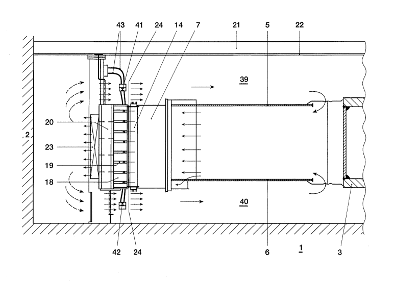
In the example, the hydroelectric machine is
completely accommodated in a foundation pit having
walls 2 and a base 1. The rotor construction comprises
a rotor hub 3, from which slanting spokes 4 radiate,
which are covered at the top and bottom by a cover ring
5 and 6 respectively. These components form the rotor
star. A rotor rim 7 is arranged at its outer periphery.
It consists of plate segments 8 which are stacked in
layers one on top of the other in a staggered manner in
2169520
- 5
the peripheral direction. In this arrangement, adjacent
plate segments 8 of a layer are distanced from one
another so that a multiplicity of radially running
cooling slits 9 are obtained which pass completely
through the rotor rim and through which cooling air can
flow radially to the outside in the arrow direction.
The mechanical connection between the slanting arms 4
and the rotor rim 7 is made in a known manner by strips
10, wedges 11 and axial slots 12 at the inner periphery
of the rotor rim 7.
At the outer periphery, the rotor rim 7 has
A~;~l ly running dovetailed slots for fastening the
rotor poles 14 provided with correspondingly formed
dovetailed pole claws 13. The rotor poles 14 carry a
pole winding 15. The structure of the rotor poles
corresponds in principle to the pole without end plates
as described in CH-A-675 799 mentioned at the beginning
and to which reference is expressly made here to avoid
repetitions. As is clearly apparent from Fig. 2, the
radial cooling slits 9 in the rotor rim 7 in each case
open out in the space between two adjacent rotor poles
14, the so-called pole gap 16, which in turn is open
toward the machine air gap 17.
The stator (Fig. 1) surrounding the rotor
comprises a stator plate body 18 which is composed of
sectional plate bodies distanced from one another and -
like the rotor rim 7 - is likewise composed of
segmented plates and has radially running cooling slits
19 between adjacent sectional plate bodies.
The stator plate body 18 is surrounded by a
stator-supporting construction 20 which is supported at
the bottom on the foundation base 1. The
stator-supporting construction 20 is fastened at the
top to the bearing-supporting star 21. Arranged on the
latter is a cover 22 which completely covers the
foundation pit and extends up to the supporting and
guide bearing (not shown in the drawing) of the
machine. At the outer periphery of the
stator-supporting construction 20, a plurality of
2169520
~~ - 6 -
air-water coolers 23 are arranged in a distributed
manner over its periphery.
In this respect, the structure described
corresponds to the prior art. In order to now realize
the cooling-air circulation according to the invention,
the rotor poles 14 have sealing plates 24 of
non-magnetic material at both end faces, which sealing
plates 24 are merely indicated in Fig. 1 and are shown
in more detail in Figures 3 to 5. These sealing plates
24, they are made, for example, of an aluminum alloy
(Anticorodal) or of glass-fiber-reinforced plastic, are
fastened in the example by means of stud bolts 25 to
the section of the pole 14 remote from the axis
independently of the clamping and supporting elements
for the pole winding 15 (Figs. 5 and 6). In Fig. 3 only
the bolts 26 passing through the pole are visible, and
the stator winding 28 held in slots in the stator plate
body 18 by means of slot wedges 27 is also shown, while
in Fig. 6 a supporting element 29 for the pole winding
15 and the conductors 30, 31 of the damper winding can
be recognized.
The sealing plates are fastened in an especially
simple manner if the last three pole plates, as in the
example, have a circular bore, corresponding to the
bolt diameter, for accommodating the bolt shank, and a
hexagonal recess for example, corresponding to the
outer contour of the bolt head and serving as an
anti-rotation locking means for the bolt, is provided
in the next pole plate on the inside. The bolts 25 are
inserted in the recess before the last three plates are
arranged in layers, and the last three plates are
slipped over the bolts 25. This type of attachment is
very efficient and simple, since it is independent of
the clamping and supporting means of the pole. The
sealing plates are also easy to exchange in the event
of a repair.
As is best apparent from Fig. 6, the sealing
plate 24 projects into the machine air gap 17 up close
to the stator bore while leaving a small gap 32
relative to the machine air gap 17. If necessary, the
2169520
slot-wedge securing means - usually a
synthetic-resin-impregnated glass cord 33 (Fig. 6)
may additionally be used to reduce the gap 32.
In the peripheral direction, the sealing plates
- apart from small gaps 34 between adjacent sealing
plates 24 - extend close together and in this way form
an annular seal, which at both end faces of the rotor
separates the machine air gap 17 from the winding-end
space.
The machine interior space may be partitioned
off from the winding-end space to an even greater
extent if, in addition, the pole gaps 16 are covered to
the outside at the end faces by a pole-gap closure
plate 35 according to Fig. 5, which represents an
enlarged plan view of the detail defined by dash lines
and designated by A in Fig. 3. This plate 35 is
preferably made of an aluminum alloy or a
glass-fiber-reinforced plastic and is provided radially
on the inside with a round widened portion 36 and is
held with the latter in an axially running round bore
37 in the rotor rim 7. It is detachably fastened
radially on the outside to the sealing plates. The
pole-gap closure plate 35 is preferably combined with a
displacement body 38 in the pole gap 16. Displacement
bodies of this type are known per se in electrical
machines having salient poles. They extend over the
entire axial length of the pole gap 16 and their task
is to fill the space between adjacent pole coils 15 in
such a way that the cooling air flows as close as
possible and at high speed past the pole coils 15.
This combination of pole-gap closure 35 and
displacement body 38 comprises a hollow body which is
open radially on the inside and is fastened at both end
faces to each pole-gap closure plate 35. It is pushed
in before assembly of the sealing plates 24 and is then
mounted together with the latter.
Completely novel cooling-air circulation for
vertical-axis hydroelectric machines can be achieved by
the invention:
2l6952o
-
-- 8 --
The (fresh) cooling air passes through openings
in the cover rings 5, 6 in the hub region into the
rotor-supporting construction and from there radially
outward to the rotor rim 7, flows through the cooling
slits 9 in the rotor rim 7, then through the pole gaps
16 into the machine air gap 17, and then through the
radial cooling slits 19 in the stator plate body 18.
The air now heated to a considerable extent is cooled
down in the air-water coolers 23 and after deflection
returns to the machine center through the spaces 39 and
40 above and below the machine. In this way, the cold
air passes the winding ends 41, 42 of the stator
winding 28 and also the winding connections and
terminal leads 43 and intensively cools these critical
parts.
The components necessary for creating the
cooling concept according to the invention are far less
voluminous than the conventional covers. The necessary
"sealing elements" have simple shapes, which are
economical to produce. Their fastening to the rotor
turns out to be simple due to the use of rotor poles
without end plates.
Obviously, numerous modifications and variations
of the present invention are possible in light of the
above teachings. It is therefore to be understood that
within the scope of the appended claims, the invention
may be practiced otherwise than as specifically
described herein.