Language selection

Search

Patent 2169658 Summary

Third-party information liability

Some of the information on this Web page has been provided by external sources. The Government of Canada is not responsible for the accuracy, reliability or currency of the information supplied by external sources. Users wishing to rely upon this information should consult directly with the source of the information. Content provided by external sources is not subject to official languages, privacy and accessibility requirements.

Claims and Abstract availability

Any discrepancies in the text and image of the Claims and Abstract are due to differing posting times. Text of the Claims and Abstract are posted:

  • At the time the application is open to public inspection;
  • At the time of issue of the patent (grant).
(12) Patent Application: (11) CA 2169658
(54) English Title: METHOD AND MANUFACTURING A ROTARY DIE CUTTING MACHINE, AND PART OF SUCH A MACHINE
(54) French Title: FABRICATION D'UNE MACHINE ROTATIVE DE DECOUPAGE A L'EMPORTE-PIECE; PARTIE D'UNE TELLE MACHINE ET METHODE CONNEXE
Status: Dead
Bibliographic Data
(51) International Patent Classification (IPC):
  • B23P 15/40 (2006.01)
  • B26F 1/44 (2006.01)
(72) Inventors :
  • RONNGARD, PER-OLOF (Sweden)
(73) Owners :
  • STALLINJESTANS LASERFORM AB (Sweden)
(71) Applicants :
(74) Agent: GOWLING LAFLEUR HENDERSON LLP
(74) Associate agent:
(45) Issued:
(86) PCT Filing Date: 1994-08-18
(87) Open to Public Inspection: 1995-02-23
Availability of licence: N/A
(25) Language of filing: English

Patent Cooperation Treaty (PCT): Yes
(86) PCT Filing Number: PCT/SE1994/000752
(87) International Publication Number: WO1995/005264
(85) National Entry: 1996-02-15

(30) Application Priority Data:
Application No. Country/Territory Date
9302667-2 Sweden 1993-08-18

Abstracts

English Abstract


A drum half of wood destined to
form part of a wooden drum for a ro-
tary die cutting machine is disclosed.
The cutting pattern (3) of the drum half
(1) is produced by means of laser beam
cutting, and the laser-beam-cut grooves
(6) extending in the circumferential di-
rection of the drum half is formed of
chain bridges (8) adjacent to the edges
of the drum half. In a method of man-
ufacturing a rotary die cutting machine
laser beam cutting is used to produce
the chain bridges in which 4-mm-long
wooden bridges (9) alternate with 4-
mm-long cuts (10).


French Abstract

Demi-tambour en bois destiné à former une partie d'un tambour en bois utilisé dans une machine de découpage à l'emporte-pièce. La matrice de découpage (3) du demi-tambour (1) est obtenue par découpage au laser, et les rainures (6) découpées au laser s'étendent dans le sens circonférentiel du demi-tambour et comprennent une suite discontinue de parties pleines (8) à proximité des bords du demi-tambour. Selon le procédé de fabrication d'une machine de découpage à l'emporte-pièce, on réalise un découpage au laser afin de produire la suite discontinue de parties pleines dans laquelle des parties pleines en bois (9) longues de 4 mm environ sont alternées avec des parties évidées (10) longues de 4 mm environ.

Claims

Note: Claims are shown in the official language in which they were submitted.


CLAIMS
1. A method of manufacturing a rotary die cutting
machine with a wooden drum that consists of two semi-
cylindrical drum halves, wherein the drum halves (1) are
provided with the desired pattern (3) by means of laser
beam cutting, and cutting rules (11, 12) are inserted in
the cut grooves (6), c h a r a c t e r i s e d in that
the grooves (6) to be cut in the circumferential direc-
tion of the wooden drum are provided adjacent to the lon-
gitudinal edges of the drum halves with such interrup-
tions as to produce a chain bridge (8) with wooden
bridges (9) of a length of about 4 mm alternating with
cuts (10) of a length of about 4 mm, said drum edge being
formed of such a bridge (9), and the chain bridge (8)
corresponding to the toothing of a cutting rule.
2. A method as set forth in claim 1, c h a r a c -
t e r i s e d in that the chain bridges have a length of
about 70-80 mm.
3. A drum half of wood destined to form part of a
wooden drum for a rotary die cutting machine, c h a r -
a c t e r i s e d in that the cutting pattern (3) of the
drum half (1) is produced by means of laser beam cutting,
and that the laser-beam-cut grooves (6) extending in the
circumferential direction of the drum half is, adjacent
to the edges of the drum half, formed of chain bridges
(8) with wooden bridges (9) of a length of about 4 mm
alternating with cuts (10) of a length of about 4 mm.

Description

Note: Descriptions are shown in the official language in which they were submitted.


-

~ W095/05264 PCT/SE9~/00752
21~6~8


fflETHOD OF MANUFACTURING A ROTARY DIE ~U~l~G MACHINE,
AND PART OF SUCH A MACHINE

This invention relates to a method of manufacturing
a rotary die cutting machine, as well as part of such a
machine.
Ba~kylo~d of the Invention
In a prior-art method of manufacturing a rotary die
cutting r~hine destined to cut e.g. package blanks, a
reduced drawing illustrating the design of the package is
glued onto a wooden drum. The contours of the drawing are
then followed and sawn by hand. However, this method is
old-fashioned in many respects, and is neither accurate
nor reliable. For instance, the prebored holes, which are
needed for introducing the saw blade, prevent the
inserted cutting rules from being firmly ret~in~.
In recent years, laser has instead been used for
cutting the groove pattern in the wooden drum, such
grooves providing a much better grip for the cutting
rule.
All cardboard cutting m~.hi n~.~., flat die as well as
rotary die cutting ma~h; n~.s, are manufactured with a
bridge system, the size of the bridges and their posi-
tions on the drum being determin~ when the cutting
machines are constructed. This is done in order to eli-
minate the "jig-saw-puzzle effect", i.e. to make all the
pieces of the drum stick together. The bridges have a
length of 8-lO mm.
Problem of the Invention
The wooden drum is usually composed of two semi-
cylindrical parts. It has, however, been found that
not even laser-beam-cut grooves adjacent to the joint
between these two parts are able to retain in reliable
fashion the cutting rules ext~n~ing in the circumferen-
tial direction of the drum, probably because the stresses
in the cut drum may act freely at the joint-defining

WO95/05264 ~ PCT/SE94/00752


edges of the drum parts. Thus, the cutting rules have
shown a tendency to straighten out at the end of the
groove curvature adjacent to these edges.
Object of the Invention
The object of the invention is to solve the above-
mentioned problem.
Sl -~y of the Invention
According to the invention, this problem is solved
by means of the chain bridges defined in the appended
claims and the following description, which replace the
prior-art circumferential groove portions adjacent to the
joint between the drum halves.
Description of an Embodiment of the Invention
An embodiment of the invention is illustrated in the
~c~ompanying drawings, in which
Fig. 1 is a plan view of two drum halves,
Fig. 2 is a perspective partial view of a drum half
which is partly provided with cutting rules, and
Figs 2A and 2B are enlarged views of the components
framed by ~he~ lines in Fig. 2.
Fig. 1 shows a wooden drum consisting of two drum
halves 1. The joint between the drum halves is designated
2. The drum halves 1 are provided with a laser-beam-cut
groove pattern 3 for cutting and scoring blanks for two
four-point-glued trays of corrugated cardboard. The
groove pattern 3 is conventionally produced, such that
8-mm-long bridges 4 remain between the cuts or slits 5.
Cutting steel rules, which have been provided with
recesses for straddling the bridges 4, are inserted in
the grooves 6 consisting of the bridges 4 and the cuts 5.
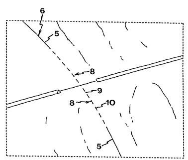
According to the invention, those parts of the cir-
cumferential grooves 6 that are located adjacent to the
drum-half edges defining the joint 2 are broken, i.e.
consist of a chain bridge 8 of 4-mm-long bridges 9 alter-
nating with 4-mm-long cuts or slits 10, one such bridge 9
defining the edge of the drum halves.

~ W095/05264 2 1 ~ 9 ~ 5 8 PCTtSE94/00752


At the top of Fig. 2A, an arcuately bent cutting
rule ll is completely inserted in a circumferential
groove 6, and at the bottom of Fig. 2A, such a cutting
rule 12 is but partly inserted in a circumferential
groove 6. It is evident from the Figure that the cut-
ting rules ll, 12 are recessed at regular 4-mm intervals
in the longitudinal direction so as to fit in the chain
bridges 8. The chain bridges 8 have a length of about
70-80 mm, but they may have any optional length, depend-
. lO ing on the design of the package and its placement on thedie.
Representative Drawing
A single figure which represents the drawing illustrating the invention.
Administrative Status

For a clearer understanding of the status of the application/patent presented on this page, the site Disclaimer , as well as the definitions for Patent , Administrative Status , Maintenance Fee  and Payment History  should be consulted.

Administrative Status

Title Date
Forecasted Issue Date Unavailable
(86) PCT Filing Date 1994-08-18
(87) PCT Publication Date 1995-02-23
(85) National Entry 1996-02-15
Dead Application 2002-08-19

Abandonment History

Abandonment Date Reason Reinstatement Date
1997-08-18 FAILURE TO PAY APPLICATION MAINTENANCE FEE 1997-10-10
2001-08-20 FAILURE TO PAY APPLICATION MAINTENANCE FEE
2001-08-20 FAILURE TO REQUEST EXAMINATION

Payment History

Fee Type Anniversary Year Due Date Amount Paid Paid Date
Application Fee $0.00 1996-02-15
Maintenance Fee - Application - New Act 2 1996-08-19 $50.00 1996-02-15
Registration of a document - section 124 $0.00 1996-05-09
Reinstatement: Failure to Pay Application Maintenance Fees $200.00 1997-10-10
Maintenance Fee - Application - New Act 3 1997-08-18 $50.00 1997-10-10
Maintenance Fee - Application - New Act 4 1998-08-18 $50.00 1998-08-11
Maintenance Fee - Application - New Act 5 1999-08-18 $75.00 1999-08-10
Maintenance Fee - Application - New Act 6 2000-08-18 $75.00 2000-07-24
Owners on Record

Note: Records showing the ownership history in alphabetical order.

Current Owners on Record
STALLINJESTANS LASERFORM AB
Past Owners on Record
RONNGARD, PER-OLOF
Past Owners that do not appear in the "Owners on Record" listing will appear in other documentation within the application.
Documents

To view selected files, please enter reCAPTCHA code :


To view images, click a link in the Document Description column. To download the documents, select one or more checkboxes in the first column and then click the "Download Selected in PDF format (Zip Archive)" or the "Download Selected as Single PDF" button.

List of published and non-published patent-specific documents on the CPD .

If you have any difficulty accessing content, you can call the Client Service Centre at 1-866-997-1936 or send them an e-mail at CIPO Client Service Centre.


Document
Description 
Date
(yyyy-mm-dd) 
Number of pages   Size of Image (KB) 
Representative Drawing 1997-06-13 1 7
Cover Page 1995-06-04 1 18
Abstract 1995-02-23 1 51
Description 1995-02-23 3 110
Claims 1995-02-23 1 38
Drawings 1995-02-23 3 49
Fees 2000-07-24 1 29
Fees 1999-08-10 1 30
Fees 1997-10-10 1 40
Fees 1998-08-11 1 37
International Preliminary Examination Report 1994-08-18 8 260
Fees 1996-02-15 1 73