Note: Descriptions are shown in the official language in which they were submitted.
~ Docket No. 7817 21 69~08
SINGLE HORIZONTAL WELLBORE PROCESS FOR THE IN-SITU
EXTRACTION OF VISCOUS OIL BY STEAM STIMULATION
FIELD OF THE Ihv~llON
This invention relates to a process for the recovery
of highly viscous oil or hydrocarbonaceous fluids from
subterranean oil reservoirs. Specifically, the invention
relates to recovering highly viscous oil using steam
stimulation in a single horizontal well.
BACKGROUND OF THE INVENTION
World energy supplies are substantially impacted by
the world's heavy oil resources. Indeed, heavy oil
comprises 2,100 billion barrels of the world's total oil
reserves. Processes for the economic recovery of these
viscous reserves are clearly important.
Asphalt, tar, and heavy oil are typically deposited
near the surface with overburden depths that span a few
feet to a few thousands of feet. In Canada, vast deposits
of heavy oil are found in the A~hAh~cca, Cold Lake, Celtic,
Lloydminster and McMurray reservoirs. In California, heavy
oil is found in the South Belridge, Midway Sunset, Kern
River and other reservoirs.
In large Athabasca and Cold Lake bitumen deposits oil
is essentially immobile - unable to flow under normal
natural drive primary recovery mechanisms. Furthermore,
oil saturations in these formations are typically large.
This limits the injectivity of a fluid (heated or cold)
into the formation. Moreover, many of these deposits are
too deep below the surface to be mined effectively and
economically.
In-situ teçhniques of recovering viscous oil and
bitumen have been the subject of much previous
investigation. These techniques can be split into three
categories: 1) cyclic processes involving injecting and
producing a viscosity reducing agent; 2) continuous
' Docket No. 7817 21 69~08
steaming processes which involve injecting a heated fluid
~ at one well and displacing oil to another set of wells; and
3) the relatively new Steam (or Solvent) Assisted Gravity
Drainage process.
Each of these techniques have large limitations if
economic application to the very viscous AthAhAsca or Cold
Lake reservoirs is desired.
Cyclic steam or solvent stimulation in these two
reservoirs are severely hampered by the lack of any
significant steam injectivity into the respective
formations. Hence, in the case of vertical wells a
formation fracture is required to obtain any significant
injectivity into the formation. Some success with a
fracturing technique has been obtained in the Cold Lake
reservoir at locations not having any significant
underlying water aquifer. However, if a water aquifer
exists beneath the vertical well located in the oil bearing
formation, fracturing during steam injection results in
early and large water influx during the production phase.
Also with fracturing it is very difficult to confine steam
where it is desired. This substantially lowers the
economic performance of wells. In addition, cyclic
steaming techniques are not continuous in nature thereby
reducing the economic viability of the process. Clearly,
steam stimulation techniques in Cold Lake and AthAhAsca are
severely limited.
Vertical well continuous steaming processes are not
technically or economically feasible in the very viscous
bitumen reservoirs. Oil mobility is simply far too small
to be produced from a cold production well as is done in
California type of reservoirs. Steam injection from one
well and production from a remote production well is not
possible unless a formation fracture is again formed.
Formation fractures between wells are very difficult to
control and there are operational problems Assoçiated with
fracturing in such a controlled manner as to intersect an
entire pattern of wells. Hence, classical steam flooding,
even in the presence of initial fluid injectivity
Docket No. 7817 2 i 69808
artificially induced by a fracture has significant
limitations.
Steam Assisted Gravity Drainage (SAGD) is disclosed in
U.S. Patent 4,344,485 which issued to Butler in 1982. SAGD
uses a pair of horizontal wells connected by a vertical
fracture. The process has several advantages to steam
stimulation or continuous steam injection. One advantage
is that initial steam injectivity is not needed as steam
rises by gravity above the upper well thereby replacing oil
produced at the lower well. Another advantage is that
since the process is gravity dominated and steam replaces
voided oil, good sweep efficiency is obtained. Yet another
advantage is since horizontal wells are utilized, good oil
rates may be obtained by simply extending the length of the
well to contact more of the oil bearing formation. In the
SAGD process, steam is injected in the upper horizontal
well while oil and water are produced at the lower
horizontal well. Steam production from the lower well is
controlled so that the entire process remains in the
gravity dominated regime. A steam chamber rises above the
upper well and oil warmed by conduction drains along the
outside of the chamber to the lower production well. The
process has the advantages of high oil rates and good
overall recovery. It can be used in the absence of a
vertical fracture.
However, one serious limitation of this process in
practical application is the need to have two parallel
horizontal wells - one beneath the other. Those skilled in
the art of drilling horizontal wells will immediately
recognize the difficulty in drilling two parallel
horizontal wells, one above the other, in thin formation
with any real accuracy for any real horizontal distance
from the surface.
U.S. Pat. Nos. 4,116,275, Butler et al; 5,148,869,
Sanchez and 5,215,149, Lu discloses steam stimulation
processes for recovering heavy oil using a single
horizontal well bore.
~1 6~08
Docket No. 7817
SUMMARY OF THE Ihv~ ON
In accordance with the present invention, highly
viscous oil is recovered from a subterranean formation
using a single horizontal wellbore subjected to steam
stimulation. First, a wellbore is drilled to penetrate the
formation comprising a substantially vertical section and a
substantially horizontal section. The vertical section of
the wellbore is cased and the horizontal section of the
wellbore is completed with a slotted liner. The wellbore
is completed with an injection tubing that extends from the
surface to the far end of the horizontal wellbore and a
production tubing that extends from the surface to the
beginning of the horizontal wellbore. After the wellbore
is suitably completed, steam is continuously circulated in
lS and out of the horizontal wellbore at a pressure below the
formation's fracture pressure thereby conduction heating
the formation surrounding the horizontal wellbore to reduce
the viscosity of the viscous oil. This step is continued
until the temperature of the horizontal wellbore reaches
the saturation temperature of steam at horizontal wellbore
pressure. Thereafter, a slug of steam is injected into the
horizontal wellbore at a pressure below the formation's
fracture pressure. Thereafter, the formation is allowed to
soak for a short period, preferably 1 to 7 days. After the
soak period, the well is then flowed back until the
production of fluids including oil substantially declines.
Thereafter, steam circulation in and out the horizontal
wellbore is resumed at a pressure below the formation's
fracture pressure thereby heating the formation surrounding
the horizontal wellbore by conduction and convective heat
to reduce the viscosity of the viscous oil and steam-
lifting fluids including oil from the horizontal wellbore.
Steam circulation is continued until oil recovery is
unfavorable. The sequence of injecting a slug of steam,
soak period, flow back and steam circulation are repeated
for a plurality of cycles until the rate of oil recovery is
unfavorable. As the cycle number increases, the size of
each succe~cive steam slug and cycle lengths also
Docket No. 7817 21 69~08
increases. During later cycle oil production rates may be
increAce~ by pumping the fluids from the well via the
production tubing instead of using steam circulation to
lift the fluids.
The present process enables the use of standard
drilling equipment and is more efficient in heating the
reservoir, thus increasing oil recovery because it makes
use of convective heating in addition to conduction heating
of the reservoir. Convective heating enhances the heating
of the reservoir 4 to 6 times, thus increasing oil
recovery.
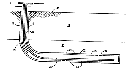
BRIEF DESCRIPTION OF THE DRAWINGS
The drawing is a schematic longitudinal sectional view
of a horizontal well utilized in carrying out the process
of the invention.
DESCRIPTION OF THE PREFERRED EMBODIMENTS
This invention is directed to a method for removing
immobile or highly viscous oil from a formation or
reservoir which formation is penetrated by a horizontal
wellbore using steam stimulation. Referring to the
drawing, the drawing illustrates a subterranean formation
or reservoir 10 which contains highly viscous oil below the
earth's surface 12, beneath an overburden 14. A wellbore
16 having a substantial vertical section 18 and a
substantially horizontal section 20 has been drilled to
penetrate the formation 10 and to extend therethrough. The
wellbore 16 is subsequently cased down to the beginning of
the horizontal wellbore 20. The entire length of the
horizontal wellbore section 20 section is lined and the
liner 22 has slots 24 over its entire surface. The
horizontal wellbore 20 and surrounding formation are in
fluid communication through slots 24. An injection tubing
26 is run inside the wellbore 16 from the surface to the
far end of the slotted liner 22. The injection tubing 26
is insulated to ensure that the quality of injected steam
exiting at the end of the tubing is as high as possible. A
production tubing 28 is run between the wellbore 16 and the
injection tubing 26 from the surface to the lower end of
21 S9~08
Docket No. 7817
the vertical section 18 of the wellbore. The annular space
30 between the vertical wellbore casing and the
injection/production tubings may be filled with an inert
gas, preferably nitrogen. The nitrogen blanket serves
three major purposes: (1) reducing heat losses to the over-
burden for better thermal efficiency and for casing
protection, (2) initiating steam-lift production mechanism
after flow-back, and (3) providing a direct measurement of
downhole pressure. Gauges may be used to monitor
bottomhole temperature and pressure directly.
Initially, after the well has been completed the
formation surrounding the horizontal wellbore is
conditioned by continuously circulating steam in and out of
the horizontal wellbore at a pressure below the formation's
fracture pressure for a time sufficient to heat the
formation surrounding the horizontal wellbore by transient
conduction. It is important not to fracture the formation
because then it would be very difficult to confine the
steam around the horizontal wellbore. Steam injection
pressure during this first step can be controlled at the
surface by adjusting chokes positioned in injection tubing
26. The steam is injected into tubing 26 at a pressure so
that the pressure of the steam in the horizontal wellbore
20 does not exceed the formation's fracture pressure.
While circulating steam, the bottomhole flow pressure is
controlled at the surface by adjusting steam circulation
rate and the choke settings in the production tubing 28.
The steam circulates down the tubing 26 to the far end of
the slotted liner 22 and back toward the heal of the
horizontal wellbore through the annular space 32 between
injection tubing 26 and the slotted liner and then up to
the surface via production tubing 28. Therefore, initially
the steam just circulates in and out of the horizontal
wellbore 20 and heats the area surrounding the horizontal
wellbore by transient conduction since penetration of the
steam into the formation 10 at these early stages is almost
nil. As the formation 10 around the horizontal wellbore 20
heats up the viscous oil becomes reduced in viscosity and
0 8
Docket No. 7817
drains into the horizontal wellbore through slots 24 in the
liner 22 creating some voidage in the formation. The
drainage of formation fluids (oil and water) is gravity
dominated. The creation of voidages in the formation 10
allows subsequent injection of steam slugs into the
formation that results in convective heating of the
formation in addition to conductive heating. Convective
heat transfer increases effective thermal conductivity by 4
to 6 times. The conditioning of the formation around the
horizontal wellbore 20 is complete when the temperature of
the horizontal wellbore reaches the saturation temperature
of steam at horizontal wellbore pressure. This may also be
indicated by a substantial amount of oil in the produced
fluids. Conditioning of the horizontal wellbore 20 is
usually complete after a period of 1 to 7 days depending
upon the injection and production pressure and steam
circulation rate. After the formation surrounding the
horizontal wellbore 20 has been suitably conditioned, a
slug of steam is injected into the horizontal wellbore 20
below fracture pressure followed by a short soak period of
1 to 7 days. After the soak period, the well is flowed
back until the produced fluids substantially decline.
Thereafter steam circulation in and out the horizontal
wellbore is resumed at a pressure below the formation's
fracture pressure and fluids including oil are steam lifted
from the horizontal wellbore to the surface via production
tubing 28. Although steam circulation continues to heat
the formation 10 surrounding the horizontal wellbore 20 it
is not normally enough to expand the heated volume around
the horizontal wellbore and oil production eventually
declines or ceases to flow. Steam circulation is continued
until the rate of oil recovery in the steam-lifted produced
fluids is unfavorable. The above sequence of injecting a
slug of steam followed by a soak period, flow back and
steam circulation is repeated for a plurality of cycles
until the rate of oil recovery is unfavorable. As the
cycle number increases, the size of each sU~Ccive steam
slug and cycle lengths also increase. The size of each
21 69808
Docket No. 7817
successive steam slug and the cycle length will depend upon
the characterization of the formation. Entering of steam
into the reservoir and the drainage of reservoir fluids
(oil and water) is gravity dominated. Also, although steam
is injected below fracture pressure, some degree of local
failure of sand in shear (dilation) takes place and is
advantageous to the process as it facilitates the entering
of steam into the formation, thus resulting in convective
heating. Further, on a cyclic basis, the cold water
equivalent of total injected fluids equals the total
produced fluids. It is preferred that the steam quality be
as high as possible to provide more heat to the formation
and thereby increase oil production. Preferably the steam
quality is at least 80% quality.
In another variation of the process, during later
cycles oil production rates may be increased by pumping the
fluids from the well rather than using steam circulation to
lift the fluids. The pump is located in the lower end of
the production tubing 28. In addition, the production of
fluids are regulated to minimize steam production. In
still another variation of the process, it is also possible
that under some reservoir conditions and with different
levels of injection pressures, the cyclic phase of the
process can be avoided, thus resulting in a process of
continuous steam injection and oil production. In this
embodiment steam is continuously injected in and out the
formation to heat the formation and lift the fluids until
the rate of oil recovery is unfavorable.