Note: Descriptions are shown in the official language in which they were submitted.
2169880
Apparatus for clamping a chipper knife
The present invention relates to an apparatus for clamping a
chipper knife to a rotatable chipper disc or drum by using a
clamping element and a knife clamp and a knife spacer
movable relative to each other for supporting a back surface
of the knife against the knife clamp.
Chippers are used for making wood chips for example from
tree trunks for the digestion of pulp or burning of wood.
The prior art is described in the publication US 4,155,384,
which discloses a disc chipper provided with a disc and
knives. The Finnish publication FI 78412 discloses a
so-called turn knife and its clamping to a disc chipper.
During chipping, a chipping force is directed to the knife
thus causing major local tensile stresses in the knife and
the knife structure must therefore be given a substantial
thickness in the direction of tensile stress. The chipper
knives are wear parts and increasing the amount of knife
material incurs an extra cost. In difficult conditions, for
example when chipping frozen wood, the knives ara subjected
to extremely great loadings. This may lead to the breakage
of a knife, which in turn adds to maintenance costs.
The object of this invention is to avoid deficiencies of the
prior art and to introduce a chipper knife which, in terms
of its thickness, can be made thinner than the knives of the
prior art and which knife is nevertheless clearly more
durable as far as breakage is concerned.
This object is achieved by an apparatus of the invention,
the said apparatus being characterized in that the knife
clamp is provided with supporting surfaces which the back
surface of the knife is adapted to support against by at
least two spaced-apart surfaces, and that the knife spacer
includes a supporting surface which is adapted to subject a
front surface of the knife to a force acting between said
_ 2169880
2
supporting surfaces of the knife clamp for bending the knife
between said supporting surfaces of the knife clamp towards
the knife clamp so as to generate a compression stress in
the non-supported section of a front surface of the knife.
Preferred further developments of the invention are set
forth in the subclaims.
A specific feature in an apparatus of the invention is that
the first support point in the back surface of the knife,
counting from the knife edge, is located close to the knife
edge, and that the free length of the front surface of the
knife, i.e. the distance between the first support point of
the front surface and the knife edge, is large compared to
'15 the distance between the first support point ~f the knife's
back surface and the knife edge. Now, when a clamping force
is directed to the knife at the first support point of the
knife's front surface, which support point lies between the
support points of the knife's back surface, the knife bends
in such a manner that a compression stress is generated on
the front surface side of the knife by the action of such
bending. At the same time, said first support points,
counting from the knife edge, on the front and back section
of the knife, are vigorously pressed against the knife.
An apparatus of the invention is capable of creating the
effect that the stresses caused by a chipping force are
distributed over the long free section of the front surface
and that the chipping force reduces the compression stress
acting on the front surface of the knife but cannot create
knife-damaging tensile stresses. Another essential feature
is that the chipping force increases the supporting forces
acting on the support points or surfaces of a knife. As a
result of these factors, dangerous vibration of the knife is
prevented and the contact of the first support points or
surfaces on the front and back side of the knife is ensured,
so as to prevent the access of wood material between the
support points and the knife.
2a
2169880
According to a first aspect of the invention, there is provided an
apparatus for clamping a wood chipper knife having front and back surfaces and
a
cutting tip to a rotatable chipper disc or drum, comprising:
a knife spacer for mounting on the disc or drum and for receiving
said chipper knife so as to support the front surface of said chipper knife;
a knife clamp movable relative to the knife spacer, for engaging the
knife spacer and supporting the back surface of the chipper knife;
a clamping element movable relative to the knife spacer and the
knife clamp, for drawing the knife clamp and knife spacer toward each other
and
thereby clamping the knife therebetween such that an unsupported portion of
the
front surface including the cutting tip is exposed to contact the wood to be
chipped;
wherein the knife clamp is provided with supporting surtaces against
which the back surface of the knife is supported by at least two spaced-apart
surfaces, and
the knife spacer includes a supporting surface which is adapted to
subject the front surface of the knife to a force acting between said
supporting
surtaces of the knife clamp for bending the knife between said supporting
surfaces of the knife clamp towards the knife clamp so as to generate a
compression stress in the unsupported portion of the front surface of the
knife.
The unsupported portion may define a free distance between the
supporting surface of the knife spacer and the tip of the knife, which is a
multiple
compared to the distance measured in the direction of the front surface of the
knife between the supporting surface of the knife clamp closest to the tip of
the
knife and the tip of the knife.
The knife may be designated as a turnable knife made of a material
having a substantially flat cross-section.
2b Z 169880
The knife may be designed as a turnable knife made of a material
having a mildly Z-shaped cross-section.
The front surface of the knife may consist of the surface of a Z-
profile projecting section extending away from a Z-profile middle section.
The knife having a Z-shaped cross-section may be designed and
clamped in such a manner that the clamping forces of the knife straighten said
knife by increasing an angle which exists between a first projecting section,
which
includes the unsupported front portion of the knife and a middle section.
The knife having a Z-shaped cross-section may be designed and
l0 clamped in such a manner that the clamping forces of the knife are adapted
through the intermediation of supporting surfaces to increase an angle between
the knife middle section and a projecting section remaining inside the
apparatus.
The knife may be provided with a thickening on the unsupported
front surface adjacent to the supporting surface of the knife spacer.
The knife clamp may comprise a body element and a knife clamp
element, the knife spacer comprises a body element and a knife spacer element,
and the knife clamp element and the knife spacer element as well as the knife
fitted therebetween are designed as a mounting unit adapted to be fitted
between
the knife clamp body element and the knife spacer body element. The mounting
unit may be provided with at least one guide surface for bringing the mounting
unit
in a controlled manner between the knife clamp body element and the knife
spacer body element and for applying a compression force to the mounting unit
through the drawing together of the body elements by said clamping element.
The
knife clamp element and the knife spacer element of the mounting unit may be
provided with mutually guiding surfaces, said surfaces guiding the knife
spacer
element and the knife clamp element relative to each other in such a manner
that,
by pressing the knife spacer element and knife clamp element of the mounting
unit between the flat surtaces of the knife spacer and knife clamp body
elements,
2169880
the supporting surfaces in the knife clamp element and knife spacer element of
the mounting unit, abutting against the knife, produce a force required for
clamping the knife, and a bending stress to the knife.
2169880
3
The invention will now be described in more detail with
reference made to the accompanying drawings, in which:
Fig. 1 shows a prior art chipper knife with its clamping
element.
Fig. 2 shows the stresses occurring in the knife of fig.
1 during the course of operation.
Fig. 3 shows a knife according to the first embodiment
of
the invention provided with a clamping element
with the knife unclamped.
Fig. 4 shows a knife according to a first embodiment of
the invention provided with a clamping element
with the knife clamped.
Fig. 5 shows a knife according to a second embodiment
of
the invention with the knife unclamped.
Fig. 6 shows a knife according to a second embodiment
of
the invention with the knife clamped.
Fig. 7 shows the solution of fig. 3 with the knife fitted
in a mounting element with the knife unclamped.
Fig. 8 shows the solution of fig. 4 with the knife fitted
in a mounting element with the knife clamped.
Fig. 9 shows the solution of fig. 5 with the knife fitted
in a mounting element with the knife unclamped.
Fig. 10 shows the solution of fig. 6 with the knife fitted
in a mounting element with the knife clamped.
Fig. 1 illustrates the clamping of a turnable knife to a
disc chipper according to one prior art. A mildly z-shaped
knife 1 is clamped by means of a clamping element 5 to a
chipper disc 4 between knife clamp 2 and knife spacer 3.
A force F2 represents the clamping force of the clamping
element 5. A force F1 represents the direction of a chipping
force applied to the knife 1 during chipping, the force
being slightly inclined in relation to the plane of the
chipper disc. The knife 1 is immobilized by forces which
result from the force F2 of the clamping element 5 and
produce supporting forces applied to supporting surfaces 6,
216980
4
7 and 8. The supporting surfaces 6, 7 and 8 are parallel to
countering surfaces of knife clamp 2 and knife spacer 3. A
vertical surface 9 of a protrusion at the other end of the
knife clamp 2 transmits to the chipper disc 4 and to the
knife spacer 3 a component of the chipping force F1, which
component is parallel to the chipper disc 4.
Fig. 2 illustrates stresses caused by the chipping force F1
in the knife 1 when using a knife as shown in fig. 1. The
knife 1 is pressed by its supporting surfaces 6, 7 and 8
between the knife clamp 2 and the knife spacer 3. The
chipping force F1 produces a major tensile stress at the
point 10. The magnitude of chipping force F1 varies widely
and it is particularly great when chipping a hard material,
such as frozen wood, whereby the knife may be subject to
vibration. The intensity of vibration may be such that the
knife may get loose from its supporting surface 8 and break,
usually at the point 10. In order to reduce the stress
directed towards the cross-sectional area of the knife and
to eliminate the knife vibration, the knife must be made
thick in the direction of its cross section.
Figs. 3-10 illustrate mechanisms for supporting a chipper
knife based on the invention. The components corresponding
to each other are designated with the same reference numbers
as in figs. 1 and 2.
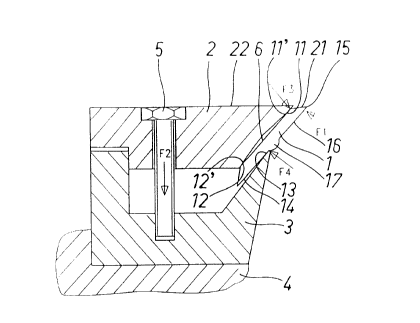
The knife 1 shown in figs. 3 and 4 is designed as a turnable
knife made of material having a substantially flat cross-
section. The clamping elements for the knife 1 comprise, as
described in reference to fig. 1, a knife clamp 2 and a
knife spacer 3 for clamping the knife 1 therebetween by
means of clamping element 5. The knife clamp 2 is provided
with supporting surfaces 11 and 12, which the back surface 6
of the knife 1 is adapted to support against by at least two
spaced-apart surfaces 11', 12'. The surfaces 11', 12' are
preferably placed in the opposite ends of the knife 1,
whereby the knife 1 forms a bended element supported by the
216988
ends. The knife spacer 3 includes a supporting surface 13,
which is adapted to apply to a front surface 14 of the knife
1 a force acting between the supporting surfaces 11, 12, of
the knife clamp 2 for bending the knife 1 between~said
5 supporting surfaces 11, 12 of the knife clamp 2 towards the
knife clamp 2 in such a manner that the free section of a
front surface 16 is subjected to a compression stress. In
fig. 4, the back surface 6 of the knife 1 is then for most
parts thereof compressed against or towards a trough-like
groove formed by the supporting surfaces 11, 12 of the knife
clamp 2. Thus, the front surface of the knife 1 is subjected
to a compression stress. In fig. 4, the trough-like groove
formed by the supporting surfaces 11, 12 is in the knife
clamp 2 but it is obvious that the groove can also be made
in the knife 1 itself.
The free distance between the supporting surface 13 of the
knife spacer 3 and a tip 15 of the knife 1 is adapted to be
multiple compared to the distance measured in the direction
of the front surface 16 of the knife 1 between the
supporting surface 11 of the knife clamp 2 closest to the
tip 15 of the knife 1 and the tip 15 of the knife 1. A
torque of the chipping force F1 acting on the tip 15 of the
knife 1 relative to the supporting surface 11 abutting
against the knife back surface 6 and closest to the knife
tip 15 becomes small as a result of the shortness of a
torque arm. This torque is compensated for by means of a
counter torque produced by means of a force F4 applied by
the supporting surface 13 of the knife spacer 3 to the knife
1, said counter torque having thus a very long torque arm.
As a result of such torque arm ratios, the chipping force on
one hand reduces the compression stress existing on the
front surface 16 of the knife 1 and, on the other hand,
increases the supporting forces F3, F4 between the knife 1
and the supporting surfaces 11 and 13, which both actions
contribute to maintaining the knife undamaged.
Adjacent to the supporting surface 13 of the knife spacer 3,
2169880
6
the knife 1 is provided with a thickening 17 in the free
front surface 16 of the knife 1. The thickening 17 is
intended to prevent chips from colliding with the knife
spacer 3 at the junction of the front surface 16 of the
knife 1 and the knife spacer and, thus, from eroding the
point in question. A slip surface 21 included in the knife 1
does not require any type of thickening provided that a top
surface 22 included in the knife clamp 2 is arranged, as
shown in fig. 4, in such a manner that the logs possibly
running along the slip surface 21 do not collide with a
corner between the top surface 22 and the supporting surface
11.
The knife 1 shown in figs. 5 and 6 is designed as a turnable
knife made of a material with a mildly Z-shaped cross-
section. Clamping elements for the knife 1 comprise, as
described in reference to fig. 1, a knife clamp 2 and a
knife spacer 3 for clamping the knife 1 therebetween by
means of a clamping element 5. It is because of the shape of
the knife 1 that the shape of the knife clamp 2 and knife
spacer 3 naturally differs to some extent from the solution
shown in figs. 3 and 4. The front surface 16 of knife 1
consists of the surface of a Z-profile projecting section 19
extending away from a Z-profile middle section 18. The knife
1 having a Z-shaped cross-section is designed and clamped in
such a manner that the clamping forces of the knife 1
straighten said knife 1, in other words, increase an angle a
between the projection section 19, which makes up the actual
knife 1, and the middle section 18.
The clamping solution for a Z-shaped knife shown in figs. 5
and 6 differs from that of a straight knife shown in figs. 3
and 4 mainly as follows.
The knife clamp 2 is provided with supporting surfaces 11,
12, which together form an angle ~ which is larger than the
angle a between the free projection section 19 and middle
2169~~0
section 18 of the knife 1. Due to this, at the initial stage
of clamping there are two line contacts at extremities 23,
24 of the flanks 18, 19 of the angle a. As for its opposite
surface, the knife 1 is initially clamped by means of a line
contact between a supporting surface 13 of the knife spacer
3 and a corner 25 between the projecting section 19 and
middle section 18 of the knife 1, said line contact
developing, as the clamping progresses, into a more
extensive surface contact as the angle a is approaching the
angle ~.
In order to achieve a reliable knife clamping, the knife
clamp 2 is provided with an extra surface 26 for a second
projecting section 28 in the knife 1 and the knife clamp 3
is provided with an extra surface 27, which are preferably
configured in disagreement with fig. 5 so that the extra
surfaces 26, 27 bend said second protrusion in such a manner
that the angle between a middle section 18 and said second
protrusion 28 decreases when the knife 1 is pressed to
position. This is to secure that the knife is placed
accurately enough in such a manner that the front surface 16
of the knife 1 is sufficiently far out to prevent the chips
sliding therealong from colliding with the supporting
surface 13 of the knife spacer 3 and, thus from eroding the
same.
When the knife 1 is clamped, a supporting force between the
knife clamp 2 and the knife 1 is at its peak at a location
23 in the knife 1. Moving away from said point 23, the
contact of the knife 1 with the knife clamp 2 diminishes in
such a manner that, near the bent portion, the apex of angle
a, there may be a small gap between the knife 1 and the
knife clamp 2. Thus, to be absolutely precise, the bending
of a knife occurring during the clamping of a knife does not
bend the knife in an exactly planar fashion but, since the
knife is made of a flexible material, the knife supporting
surface bends into the shape of a slightly curved plane,
including the location 23 which is, as noted above, in the
tightest contact with its abutting surface of the knife
2169880
clamp 2.
As a result of the above, rapidly changing chipping force F1
does not cause dangerous vibration of the knife or
disengagement of the knife contact from the surface of the
knife clamp at point 23. The stress condition of the knife
caused by pretensioning is such that it compensates for the
stresses caused by the chipping force F1 on the surface 16
and the knife has a low maximum stress value. For the above
reasons it is possible to make a knife of the invention
substantially thinner and still to achieve, as far as the
knife breakage is concerned, a clearly improved reliability
over the prior art solutions.
Thus, a knife of the invention will be cheaper in price than
the prior art knives and the maintenance costs of knives
(chippers) are reduced with fewer knife breakages.
Figs. 7-10 illustrate yet another preferred embodiment of
the invention which is configured so that the knife clamp
comprises a body element 2' and a knife clamp 2, that the
knife spacer comprises a body element 3' and a knife spacer
3, and that the knife clamp 2 and the knife spacer 3 as well
as a knife 1 fitted therebetween are designed as a mounting
element, which comprises an integral unit and is adapted to
be fitted between the knife clamp body element 2' and the
knife spacer body element 3'. When using a mounting element,
it is possible to carry out in a simple manner the machining
of precision-demanding surfaces included in the knife clamp
2 and the knife spacer 3 and coming against the knife 1. The
surfaces between the mounting element and the body element
2' as well as the mounting element and the body element 3'
are preferably straight flat surfaces.
The mounting element is provided with at least one guide
surface 20 for bringing the mounting element in a controlled
manner between the knife clamp body element 2' and the knife
spacer body element 3' and for applying a compression force
2169880
9
to the mounting element through the body elements 2' and 3'.
Thus, a mounting element assembled into an integral unit
outside the chipper by means of screws 30 in a per se known
manner (fig. 9) can be fitted in position quickly and
accurately, whereafter clamping of the element and bending
of a knife in the element are carried out by means of a
clamping element 5.
The knife clamp 2 and the knife spacer 3 of the mounting
element are provided with mutually guiding surfaces 29 and
30, said surfaces guiding the knife spacer 3 and the knife
clamp 2 relative to each other in such a manner that, by
pressing the knife spacer 3 and knife clamp 2 of the
mounting element between the flat surfaces in the knife
spacer and knife clamp body elements 3' and 2', the
supporting surfaces included in the knife clamp 2 and knife
spacer 3 of the mounting element and abutting against the
knife produce a force required for clamping the knife and a
bending stress to the knife.