Note: Descriptions are shown in the official language in which they were submitted.
2~.6989t~
-1-
FIELD OF THE INVENTION
This invention relates to the field of medical
instrumentation, and in particular to a bridge that can
be used for electrical monitoring or electrical
stimulation of a biological entity.
BACKGROUND TO THE INVENTION
Electrical monitoring or stimulation of a
biological entity such as an organ has been effected in
the past by the use of metal conductors which are in
to contact with the biological entity (to be referred to
generically as an organ in this specification). While
it has been important that the metal conductors are
constituted by a material that can be tolerated by the
organ (or body through which the conductor passes), a
major problem arises when the conductors are located in
the environment of a high intensity moving magnetic
field, e.g. an electromagnetic field such as is
generated by a magnetic resonance imaging (MRI) machine.
The moving high intensity electromagnetic field
2o generates electric currents in the metal conductors,
which can adversely affect normal operation of the organ
which it touches, and can change or otherwise affect the
signals picked up by the MRI machine, resulting in poor
or incorrect interpretation of the form of the organ,
hiding of formations, and/or incorrect diagnosis of a
problem associated with the organ.
An example of the above is an attempt to use
an MRI machine to observe operation of a heart the
beating of which is timed by means of a pacemaker
3o connected to the heart by metal wires.
SUMMARY OF THE INVENTION
The present invention is a bridge that can be
used to carry current to or from an organ, such as a
heart, without the use of metal wires. We have found
that the present invention is substantially unaffected
CA 02169890 2001-O1-18
-2-
by the moving electromagnetic field generated in an MRI
machine, and has little or no effect on the resulting
signals picked up by the MRI machine. Accordingly the
invention can be used to pace the heart or to monitor
the heart in the presence of such electromagnetic
fields. In addition, the invention can be used for
other purposes, such as for electrocardiogram
monitoring, electroencephalogram monitoring, etc.,
whether or not an electromagnetic field is present.
1o A novel portable connection capsule has been
invented which can be used to connect the bridge to
monitoring apparatus.
In accordance with an embodiment of the
invention, an electrical bridge for communicating
signals to or from an organ or a patient is comprised of
a non-porous, non-metallic, flexible tubular duct, an
sonically conductive liquid contained in the duct for
transmitting electrical signals by ion transfer and a
non-metallic conductive plug at an end of the duct for
electrically connecting to the organ or patient.
In accordance with another embodiment, a
method of communicating signals to or from an organ or a
patient within the environment of an MRI machine is
comprised of providing a non-porous, non-metallic,
flexible tubular duct filled with an sonically
conductive liquid for transmitting electrical signals by
ion transfer, and providing a non-metallic conductive
plug at an end of the duct electrically connected to the
organ or patient.
In accordance with another embodiment, a
method of communicating signals to or from an organ or a
patient within the environment of an MRI machine is
comprised of providing a non-porous, non-metallic,
flexible tubular duct filled with an sonically
conductive liquid for transmitting electrical signals by
~~69~9Q
-3-
ion transfer, providing an electrical connection between
the patient and the liquid and providing an electrical
connection from the liquid to a metal conductor by
immersing the end of the duct and the conductor into an
ionically conductive liquid or gel bath.
In accordance with another embodiment, a
method of applying signals to an organ is comprised of
connecting a pair of ionic conducting bridges to the
organ, each bridge being comprised of an insulating tube
filled with a liquid salt solution, a porous plug at one
end of each tube touching the organ, immersing opposite
ends of the tubes in separate reservoirs containing
liquid salt solutions, immersing one end of a pair of
metal wires into respective ones of the reservoirs, and
connecting the other ends of the wires to an electric
generator for generating the signals.
In accordance with another embodiment, a
method of monitoring signals generated in an organ is
comprised of connecting at least a pair of ionic
conducting bridges to a body containing the organ, each
bridge being comprised of an insulating tube filled with
a liquid salt solution, a porous plug at one end of each
tube touching the body, immersing opposite ends of the
tubes in separate reservoirs containing liquid salt
solutions, immersing one end of each wire of a
corresponding at least a pair of metal wires into
respective ones of the reservoirs, and connecting the
other ends of the wires to an electrical signal
monitoring device.
In accordance with another embodiment, an
ionic conductor is comprised of a long tube filled with
thixotropic gel comprising a salt solution, a porous
plug closing one end of the tube, a non-porous plug
closing the other end of the tube, and a metal wire
CA 02169890 2001-O1-18
-4-
extending through the non-porous plug into the gel and
having a free end outside the non-porous plug.
BRIEF INTRODUCTION TO THE DRAWINGS -
A better understanding of the invention will
be obtained by considering the detailed description
below, with reference to the following drawings, in
which:
Figure 1 is a schematic drawing of a first
embodiment of the invention in use,
l0 Figure 2 is a schematic drawing of a second
embodiment of the invention in use, and
Figure 3 is a cross-section of a third
embodiment of the invention, a bridge connection capsule
which can form part of the embodiments of Figures 2 or
3 .
DETAILED DESCRIPTION OF PREFERRED EMBODIMENTS
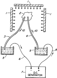
Figure l shows an excised heart 2 which is to
be paced in an MRI spectroscopy environment, in order to
obtain scientific or pharmacological determinations
using MRI spectroscopy. Since MRI exhibits very high
electromagnetic fields as well as very high radio
frequencies, it is difficult to obtain good signal to
noise ratios, to determine the data required. Since
pacing is done with convention D.C. signal generators,
the current and voltage delivered, to pace the heart,
requires leads to and from the heart 2 that pass through
the MRI electromagnetic fields. Platinum or other
conventional metal leads present a major problem in the
high radio frequency fields. In the high
3o electromagnetic environment of the MRI, the signal to
noise ratio is very low and it is difficult to obtain a
signal carrying the information required.
Two ion salt bridges 3 and 4 are used which in
effect are wireless and non-metallic. When they are used
for pacing heart 2, the signal to noise ratios have been
CA 02169890 2001-O1-18
-$-
found to be sufficiently high that pharmacological or
scientific data can be obtained. The heart 2 is paced
by D.C. voltage and current provided from generator 7
via reservoirs 5 and 9 which form bridge junctions.
Metal lead wires 6 and 8 are connected between generator
7 and reservoirs 5 and 9 and ion bridges 3 and 4 are
connected between reservoirs 5 and 9 and the heart 2 to
be paced. A current path thus is provided from
generator 7 to reservoir 9 via lead wire 8, from
l0 reservoir 9 via bridge 4 to heart 2, from heart 2 via
bridge 3 to reservoir 5 and via metal lead wire 6 to
generator 7.
The bridges 3 and 4 are preferably 48" or
longer so that the reservoirs 5 and 9 and generator 7
are out of range of the radio frequency fields and
magnetic effects of the MRI machine.
MRI measurements are made, which is made
possible because the bridges 3 and 4 are wireless and
non-metallic. The bridges are preferably made of 2 mm
(but can be smaller or larger) polyethylene tubing,
filled with a thixotropic gel of 3.6 molar KCL. Inside
the full length of the 48 inches or more is a saturated
cotton thread. The gel and cotton thread fill the
tubing to ensure against bubbles, air locks, dry out and
crystallization.
Each end of the ion bridges 3 and 4 are
terminated in each tapered fibrous (pulp) porous
junctions with the cotton thread in contact with each
pulp junction. The pulp junctions and the cotton thread
should be saturated in a 4 molar KCL before production
is undertaken. When not in use the ion bridges should
be stored in 4 molar KCL solution.
The above-described ion bridges conduct the
ions which have been found to be unaffected by the R.F.
Reservoirs S and 9 which act as intermediaries
CA 02169890 2001-O1-18
-6-
(junctions) between the D.C. generator 7 and leads 6 and
8. Ion bridges 3 and 4 continue ion and thus current
flow to the heart being paced, without being
substantially affected by, or affecting the MRI
electromagnetic field.
The ion bridges 3 and 4 can be made longer, if
more distance is needed to place the reservoir leads 6
and 8 out of the influence of the MRI electromagnetic
field. The gel composition and cross section of the ion
to bridge can be altered to increase current flow just as
one would change the wire size and length to do the
same.
The ion bridges 3 and 4 and reservoirs 5 and 9
are inexpensive to fabricate, can be sterilized, are
storable and are reusable.
Figure 2 shows a patient 2 in an MRI machine,
subjected to a high electromagnetic field. In the
conventional method the patient is to be connected to an
electrocardiogram (E.K.G.). However use of a
conventional EKG monitor, lead wires, and monitoring
electrodes, is difficult or impossible since the metal
in the lead wires and electrodes make the signal to
noise ratio too low as a result of the high R.F. and
high electromagnetic field of the MRI machine. The
present invention overcomes this problem by providing a
wireless, non-metallic bridge in place of the metal
leads, and which does not reduce the signal to noise
ratio. This permits the monitoring of a high risk,
critically ill patient during an MRI procedure.
The procedure uses, for example, three bridges
and connectors to obtain an acceptable E.K.G. trace and
heart rate.
A conventional E.K.G. machine 20 is used that
displays e.g. trace 21 and heart rate 22. The E.K.G.
cables 17, 18, 19 are typically connected to a junction
~~.69&~(~
block 16. Three metal leads 13, 14, 15 connect to block
16 in order to connect to corresponding leads 17, 18 and
19 respectively. The other ends of leads 13, 14, 15 are
dropped into reservoirs 10, 11 and 12. Reservoirs 10,
il and 12 are located outside of the environment of the
MRI electromagnetic field as well as the monitor 20,
cables 17, 18, 19, 13, 14, 15 and block 16.
The reservoirs 10, 11 and 12 contain a 4 molar
KCL solution as in the first embodiment of the invention
to described with reference to Figure 1. Reservoirs 10, 11
and 12 interface metal leads 13, 14, 15 with ion bridges
7, 8 and 9. Ion bridges 7, 8 and 9 are physiological
ion salt bridges that carry signals from the patient 2
to the monitor 20 via reservoirs 10, 11, 12 and leads
13, 14, 15, 17, 18, 19.
The leads 7, 8, 9 are preferably about 48"
long, are metalless and wireless, conduct ions and are
substantially unaffected by the high radio frequency
fields and the high electromagnetic fields of the MRI
machine 1. The construction and design of the ion
bridges are similar to that described with reference to
the embodiment of Figure 1.
The ion bridges 7, 8 and 9 must be connected
to the patient 2 to carry the signal to monitor 20. The
connection is effected by electrodes 4, 5 and 6. These
are preferably comprised of a 2" or small foam or tape
adhesive, to which is attached a 2 cm plastic
(biocompatible) cup or well to hold a column of 3.6
molar KCL gel (the same gel as in the ion bridge). A
small recess is cut in the plastic well to accept and
hold a corresponding ion bridges 7, 8 or 9. Electrodes
4, 5 and 6 and ion bridges 7, 8 and 9 can be adhered to
the patient by the acrylic adhesiveness of the foam or
tape pad. The monitoring electrodes 4, 5 and 6 can be
for one time use, and disposable. A syringe, containing
CA 02169890 2001-O1-18
_g_
the 3.6 molar KCL gel can be supplied with a pack of the
electrodes 4, 5 and 6 and used to fill each well.
As with the fist embodiment, the 48" or longer
length of the bridges 7, 8, 9 make it possible for the
reservoirs 10, 11, 12, cables 13, 14, 15, 17, 18, 19 and
block 16 and monitor 20 be out of the environment of the
NCI electromagnetic and radio frequency fields
effectively monitor the patient.
Figure 3 illustrates the cross-section of
to another form of the liquid connection reservoirs 10, 11
and 12 described above, in the form of a capsule 30.
The arrangement is provided in order to be able to
monitor or pace an animal or human heart or any other
organ in an MRI or NMRI spectroscopy environment, as
described above, using the wireless, nonmetallic ion
bridge described herein.
The capsule 30 can replace the liquid
junctions 5, 9, 10, 11, 12 since the latter junctions
have limitations due to size, bulk, and spilling,
especially when used in an NMRI nuclear magnetic
resonance imaging, or spectroscopy environment. The
capsule or connector comprises a bridge as will be
described and a short metal (e.g. copper) wire lead 34.
The medium for conducting the ion flow in the bridge is
the same gel used in the earlier described ion KCL salt
bridges, which results in less chance of developing
junction potentials.
Each capsule 30 is comprised of a preferably
10 foot to 13 foot or longer ion KCL salt bridge 32
extending from one end. A metal (e. g. copper) very
short lead 34 extends from the other end.
The capsule 30 in the drawing is an apparatus
of transferring electron flow from an ion KCL wireless
nonmetallic bridge or conductor to a short metal
CA 02169890 2001-O1-18
-9-
conductor. The very short metal conductor has been
determined not to affect the MRI signal at the MRI end.
For E.C.G., or E.E.G. monitoring in an MRI
environment, the embodiment of Figure 3 can be used.
The ion bridge 32 is connected to the subject or patient
for each of 3 leads or 5 leads of the E.C.G, or E.E.G.
The length allows the capsule and wire 34 to be located
out of the NNEtI environment. Wire 34 connects to the
instrument doing the measurement.
To monitor pH in an organ in an MRI
environment, a 10 t0 13 foot or longer ion bridge
terminating in capsule 30 can be used with the short
wire 34 connected to the pH electrode or other ion
electrodes. The other end or a second capsule are
located out of the NMRI environment, with wire 34
connected to the instrument doing the recording.
The capsule 30 in Figure 3 is preferably
comprised of a 2 inch long barrel of 1 c.c. syringe 36,
forming a cylindrical tube, and two rubber bushings 38
each closing a correspond end of the tube. The tube is
filled with thixotropic gel 40 (same as the gel in
bridge 32). An ion KCL bridge 32 which is preferably 10
to 13 feet or longer as previously described, includes a
tubular duct, gel 40 and cotton strand 42 or yarn with
the cotton strand or yarn projecting outward from the
end of a plug of the duct at the remote end.
A short copper wire 34, generally less than 2
inches long and .025" diameter extends from the gel 40
outwardly through bushing 38.
Preferably a fibrous strain relief 44 is used
for wire 34. The cotton thread 42 extends into the
cylinder 36.
The capsule 36 is light, compact, and has been
found to be easier to use and is more rugged than the
earlier described liquid reservoir system of converting
2.~ ~9~~~
or transferring the electron flow from the ion KCL gel
bridge to a very short copper wire.
Applications of the above described invention
are for example to pace a patient's or animal's heart,
be it pig, toad, rat or other hearts and organs, during
an MRI spectroscopy procedure using two physiological
ion salt bridges and two reservoirs filled with 4 molar
KCL solution, to monitor a patient's or animal's heart
during an MRI procedure using for example three
1o physiological ion salt bridges and three reservoirs
filled with 4 molar KCL solution. The reservoirs can be
generally as described with reference to Figures 1 or 2,
or as described with reference to Figure 3.
A person understanding this invention may now
conceive of alternative structures and embodiments or
variations of the above. All of those which fall within
the scope of the claims appended hereto are considered
to be part of the present invention.