Note: Descriptions are shown in the official language in which they were submitted.
-
~ 7 ~
The invention relates to a cigarette tube filling
device with a housing bottom part having an approximately semi-
cylindrical lower half of a press chamber for forming a shaped
tobacco article.
A cigarette tube filling device of this type is known
from DE 2,159,054. In this, the housing bottom part is made
block-like and on the top side has, to form the press chamber,
an approximately semicylindrical recess on which rests a thin-
walled semicylindrical tongue at an end of which remote from the
ejection nozzle are provided the abutment and a pin-shaped
extension projecting outward through a slot at the housing
bottom part transversely to the axis of the press chamber. In
one embodiment, finger engagement takes place directly on a
spherical thickening of the extension, and in another embodiment
there is provided a slide which engages over the housing top
part pivoted downward onto the housing bottom part and which
grasps the end of the extension by means of a perforation and
offers a relatively large engagement surface.
In both cases, the guidance of the tongue leaves much
to be desired. The propulsive force exerted on the end of the
extension on the outside leads to a bending moment which is
conducted to the end of the thin-walled tongue. This results
in a one-sided bearing of the tongue in the semicylindrical
recess of the housing bottom part and in considerable friction.
The forces, already appreciable in any case, which are necessary
for pushing out the formed pressurized tobacco strand into the
cigarette tube are further intensified as a result of the
friction.
23473-172
4'~, A
- 2 - ~ g ~ ~
The known embodiment is also complicated to produce,
either because the housing bottom part must be openable at the
end so that the tongue together with the abutment and the
extension can be pushed in from the end, or because a separate
extension has to be connected to the tongue and the abutment
through the slot from the side.
DE 2,055,673C discloses a similar cigarette tube
filling device which, laterally of the actual filling device,
also comprises a storage space for tobacco.
In this case, the extension located on the tongue is
angled at 90~ and extends through a corresponding duct to the
side wall where an actuating knob is provided. At the same
time, the tongue forms in a self-supporting manner the lower
half of the press volume. However, guidance in the angled duct
easily leads to tilting and, moreover, makes it necessary for
the housing bottom part to be composed of a plurality of parts
in the region of this duct.
The object on which the invention is based is to
design a generic cigarette tube filling machine in such a way
that it works smoothly and is easy to assemble.
The invention provides cigarette tube filling device
comprising: a housing bottom part in which is formed an
approximately semicylindrical lower half of a press chamber
for the shaped tobacco article; a housing top part in which is
formed an approximately semicylindrical upper half of the press
chamber and which can be pivoted downward from an opened
position, in which the tobacco for the shaped tobacco article
23473-172
A
- 3 -
can be introduced into the lower half of the press chamber,
onto the housing bottom part about an axis parallel to the
axis of the press chamber and located laterally outside the
press chamber to a closed position to form an essentially
closed and essentially cylindrical press chamber; a nozzle
which is arranged at one end of the press chamber and is
concentric to the latter and which has an approximately
identical inside diameter for slipping on a cigarette tube;
a device activated when the housing top part is pivoted downward
for clamping the cigarette tube on the nozzle; a flute-shaped
tongue which extends in the housing bottom part along the press
chamber over a substantial part of the length of the press
chamber and onto which the tobacco for the shaped tobacco
article can be applied; a slide at that end of the press
chamber facing away from the nozzle, which slide is connected
to the tongue, forms an abutment for the end of the shaped
tobacco article and is displaceable along the press chamber;
and an extension of the slide which extension engages through
a lateral slot of the housing bottom part and forms a unitary
component with the slide and the tongue and on which extension
a handle for displacing the slide and the tongue along the
press chamber is arranged outside the housing bottom part,
characterized in that the housing bottom part is itself sub-
divided at a separating plane and consists of a trough-shaped
base part and of a cover part arranged above the latter, in
that there is provided in one of the parts of the housing
bottom part a straight guide parallel to the press chamber and
engaging on the slide for the component consisting of tongue,
23473-172
A
- 3a -
slide and extension, and in that, with the base part and cover
part separated, the component consisting of tongue, slide and
extension can be inserted into the housing bottom part trans-
versely to the separating plane and, after the base part and
the cover part have been assembled, the elements of the straight
guide are inseparably in operation.
By virtue of this design, the component consisting of
tongue, slide and extension can be inserted into the base part,
whereupon the cover part is attached and assembled together with
the base part. This assembly alone at the same time brings into
operation the straight guide which ensures exact support
against the propulsive forces, without the tongue itself having
to perform the guidance.
Preferably, assembly of the two parts of the housing
bottom part takes place by means of a snap connection, so that
assembly can be carried out virtually with one manipulation.
For reasons of a saving of space, it is recommended
to arrange the guideweb on the sides of the press chamber which
face the extension.
Since the tongue forms in a self-supporting manner
the lower part of the press chamber, the tongue is exposed to
the pressure caused by the compression of the tobacco strand
when the housing top part is pivoted downward and the tobacco
strand is formed. For support against this pressure, a support-
ing web may be provided beneath the tongue. Preferably the
handle extends laterally next to and over the entire height of
the housing and can be grasped simultaneously by two fingers
from above and below. As a result of this design, the guidance
23473-172
r,~
-
- 3b -
of the handle, that is to say the extension of the slide, is
not loaded by the handle grasping forces. Moreover, in this
case, the exertion of the propulsive force presents
particularly few problems.
An exemplary embodiment of the invention is
illustrated in the drawings.
Figure 1 shows a perspective view of the cigarette
tube filling device in the initial state;
23473-172
iA ~
2169924
-- 4
Figure 2 shows a view according to Figure 1 from
the left on an enlarged scale;
Figure 3 shows a perspective view of the ciga-
rette tube filling device, with the housing top part
swung open;
Figure 4 shows a perspective view of the ciga-
rette tube filling device after the filling of a ciga-
rette tube has taken place;
Figure 5 shows a cross section approximately
along the line IV-IV in Figure 1;
Figure 6 shows a side view of the component
comprising the tongue, the slide and the extension
together with the handle, in section along the line VI-VI
in Figure 8;
Figure 7 shows a view according to Figure 6 from
the left;
Figure 8 shows a view according to Figure 6 from
above in section along the line VIII-VIII.
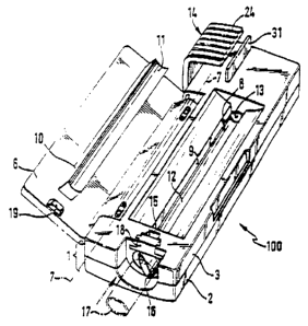
The cigarette tube filling device, designated as
a whole by 100 in Figure 1, is represented there approxi-
mately in its natural size. It has a generally elongately
cuboidal outer shape, the longest side of the cuboid
exten~;ng parallel to the press chPmher. The cigarette
tube filling device 100 can therefore be carried conveni-
ently in the jacket pocket.
The cigarette tube filling device 100 comprises
a housing bottom part 1 which itself consists of a base
part 2 and a cover part 3 which are separated along a
separating plane 5 approximately parallel to the base
~ ., 2169924
-- 5
surface 4 and which can be connected to one another by
means of hook-like snap connections attached at a plura-
lity of locations and not reproduced in the drawings.
In the normal operating position evident in
Figures 1, 3 and 4, when the cigarette tube filling
device is being used, the latter rests with the base
surface 4 on a horizontal bed, for example a table. The
horizontal projections of the base part 2 and of the
cover part 3 of the housing bottom part 1 overlap one
another in this case.
In the region of an upper lateral longit~ ;nAl
edge, the housing top part 6 is mounted foldably or
pivotably in a lid-like manner about a pivot axis 7. The
hou~ing top part extend~ over approximately three-
quarters of the length of the housing bottom part, that
is to say approximately over the length of a cigarette.
The housing top part 6 has, on the underside facing the
housing bottom part 1 during pivoting, a longitl~;nA1 web
10 which, on its lower edge, has a part-cylindrically
concave recess 11 which, when the lid-like housing top
part 6 is "folded shut", enters a correspQr~;ng elongate
recess 9 o$ the cover part 3 of the housing bottom part.
The press chamber, designated as a whole by 8, is formed
in the recess 9, which press chamber, according to Figure
3, is limited upward by the part-cylindrical recess 11 of
the housing top part 6 and downward by a semicylin-
drically bowl-shaped tongue 12. The reces~ 11 and the
tongue 12 together limit the approximately cylindrical
press chamber 8, the diameter and length of which corres-
2169g24
_ -- 6
pond approximately to a cigarette.
That end of the press chamber 8 at the top inFigure 3 is formed by an abutment 13 perpendicular to the
axis of the press chamber 8 and formed on a slide 20
(Figure 5) which is guided in the housing bottom part 1
on a straight guide ext~n~;ng parallel to the axis of the
press chamber 8 and which can be displaced forward on a
handle 14 according to Figures 1, 3 and 4, as is evident
from Figure 4. The tongue 12 and the abutment 13 are
taken up during this movement.
The wall 15 at that end of the press chamber 8
facing away from the abutment 13 in the position
according to Figure 3 has a perforation in the axial
direction, the diameter of which corresponds
approximately to that of a cigarette and which is
surrounded by a nozzle 16 connected to the cover part 3.
The nozzle 16 projects from the front side of the wall 15
and is exposed all-round, 80 that a finished cigarette
tube 17 can be pushed onto the nozzle 16 in the way
indicated by dot-and-dash lines in Figure 3.
Mounted above the nozzle 16 in the cover part 3
is an elastomeric body 18 which is freely accessible from
above and which, in the relieved state reproduced in
Figure 3, leaves with its underside a small clearance
relative to the top side of the nozzle 16, 80 that the
pll~h; ng on of the cigarette tube 17 is not impeded.
Provided on the underside of the housing top part
6 is a projection 19 which, when the housing top part 6
is folded shut, exactly meets the elastomeric body 18 and
~ 1 ~992~1
-- 7
deforms the latter in the way evident from Figure 2, with
the result that the latter comes into place with its
underside firmly on that end of the cigarette tube 17
~upported by the nozzle 16 and clamps the cigarette tube
17 against forces which endeavor to pull the cigarette
tube 17 off from the nozzle 16.
The initial position for producing a cigarette i8
reproduced in Figure 3. The housing top part 6 is folded
open. The press chamber 8 is accessible from above. Loose
tobacco is now introduced into the press chamber 8 as
evenly as possible in a quantity sufficient for a ciga-
rette. The cigarette tube 17 is slipped onto the nozzle
16. The housing top part 6 is then pivoted downward and
the loose tobacco is pressed by the web 10 to form an
approximately cylindrical strand which rests on the
tongue 12. With the housing top part closed the molding
18 retains the cigarette tube 17 on the nozzle 16.
The tongue 12 is now pushed forward according to
Figure 4 by means of the handle 14, the tongue 12 passing
through the nozzle 16 into the cigarette tube and t~k; ng
up the tobacco strand which is pushed by the abutment 18.
In the position shown in Figure 4, the tobacco strand i~
transferred completely into the cigarette tube 17.
The handle 14 is then returned again into the
rear position reproduced in Figures 1 and 3, the tongue
12 being drawn out of the cigarette tube 17 and the
tobacco strand remaining in the cigarette tube 17 on
account of the greater friction on the paper of the
latter. The housing top part can then be released, with
216~921
-- 8
the result that the elastomeric molding 18 i8 relieved
and the cigarette tube 17, filled with tobacco, can be
pulled off from the nozzle 16.
The design of the cigarette tube filling machine
100 on the inside emerges from Figures 5 to 8. It is
evident from the cross section of Figure 5 that the
tongue 12 together with the abutment 13 is attached to a
slide, designated as a whole by 20, from which an exten-
sion 21 approximately parallel to the base surface 4 of
the base part 2 and located in the region of the inter-
face between the base part 2 and the cover part 3 extends
outward through a lateral slot 22 of the housing bottom
part. The handle 14 sits on the extension 21 just outside
the housing bottom part 1 and has a part 23 which extends
approximately over the height of the housing bottom part
plus the housing top part 6 and which has at the top,
just above the housing top part 6, an angling 24
partially engaging over the housing top part 6 and, at
the bottom, an equidirectional angling 25 which engages
into a correspon~;ng recess 26 of the base part 3 and
which, with its underside, is aligned with the base
surface. The handle 14 can thereby be grasped with two
fingers simultaneously from above and below, 80 that the
grasping forces do not load the guide of the slide.
The slide 20 extends between the press chamber 8
and the handle 14. The straight guide of the slide 20
comprises a guide web 27 which projects upward from the
bottom of the trough-shaped or bowl-shaped ba~e part 2,
narrows slightly upward and [lacuna] parallel to the
21~9~2~
g
pre~s chamber 8 over a [lacuna] correspon~; ng to the
cigarette and therefore to the advance of the slide 20
and which, according to Figure 5, engages from below into
a correspon~;ng recess 28 of the slide 20, which recess
28 surround [sic] the web 27 with only slight play, but
still in an easily slidable manner.
A web 29 rl~nn;ng approximately parallel to the
bottom of the base part 2 extends from the slide 20
toward the press chamber 8, which web 29 is angled upward
in the region of the press chamber 8 and is connected to
the underside of the tongue 12 at a point located outside
its center on the side of the slide 20. The tongue 12 is
therefore kept completely free by the straight guide 27,
28 from tilting moments exerted by the handle 14.
When tobacco is located in the press chamber 8
and i8 compressed during the downward pivoting of the
housing top part 6, according to Figure 5 the tongue 12
experiences downward-directed forces, against which it is
supported as a result of the bearing of its lower region
on a supporting web 30 projecting from the bottom of the
base part 2 and ext~n~;ng parallel to the press chamber
8.
The tongue 12, slide 20, extension 21 and handle
14 form a unitary component 40 which is represented in
Figures 6 to 8. This component, like the rem~;n;ng parts
of the cigarette tube filling device 100, can be
injection-molded from plastic. The length of the tongue
12 from the left-hand end 12' as far as the abutment 13
corresponds to the length of the tobacco strand in the
2169924
- 10 -
cigarette. The length of the handle 14, especially of the
upper part 24, i8 selected in such a way that it covers
that rear part of the housing bottom part 1 which i~ free
of the housing top part 6, as is evident from Figures 1
and 3, 80 that, in this position of the handle 14, the
housing top part 6 can be swung upward. The height of the
handle 6 above the cover part 3 is selected in such a way
that the part 24 of the handle can be guided over the
housing top part 6 with a slight clearance, as is evident
from Figures 4 and 5. Provided on the top side of the
cover part 3, in the vicinity of the overhanging edge of
the part 24 of the handle 14, i8 a web 31 which is to
cover the gap between the part 24 and the top side of the
cover part 3, 80 that no foreign bodies infiltrate
between them in the transport position reproduced in
Figure 1.
The assembly of the cigarette tube filling device
100 is particularly simple. It is necessary merely to
attach the housing top part 6 pivotably to the cover part
3. The component of Figure 6 to 8, designated as a whole
by 40, is inserted into the base part 2 of the housing
bottom part. The cover part is then placed on top and
fastened by snapping in. The straight guide 27, 28 is
consequently activated without the parts being capable of
coming loose from one another again and without detach-
able housing parts having to be present, for example on
the end faces. A housing design essentially closed all-
round and protected against the penetration of dirt is
obtained.