Note: Descriptions are shown in the official language in which they were submitted.
2 1 69~86
PROCESS FOR AUTOMATICALLY CONTROLLING A CROP PROCESSING UNIT
BACKGROUND OF THE INVENTION
1. Field of the Invention:
The invention is directed to a process for aulo,nalically controlling at least
one crop processing unit in a harvesting machine.
2. Description of the Prior Art:
Currently combines operated by custom harvesters are operated at
extremely high harvesting car~cities. This harvesting capacity can only be
attained, if such a combine is optimally adjusted. The sieve aperture, the blower
output, the degree of threshing, must be adjusted to lead to the maximum possible
threshing, the least possible amount of straw and chaff output, the least possible
15 loss of grain, the highest possible degree of grain cleanliness and the fewest
possible damaged kernels. Since these adjustments are dependent upon the
particular variety of crop, crop condition, the operating condition of the cG",bi"e and
other factors, there is no single correct adjustment, but rather, an unending
multitude of adjustment combinations, among which the correct one must be found
20 at any given time. It is impossiLI- for an operator to optimally update these adjustments at all times and at the proper time.
It is therefore known (EP-B1-0 339 141, EP-B1-0 339 140, DE-C2-29 03
910) to perform adjustments on combines automatically. For this purpose, loss
sensors can be used to determine in relative or absolute terms, how much grain is
25 deposited on the ground from the separating or the cleaning arrangement of the
combine. This loss information can be used to vary the flow of the crop over thecleaning arrangement, the blower output, the total throughput of the machine andthe like. According to US4,360,998 instead of loss sensors, the loss is calcu~ted
by a function extrapolated beyond the end of the sieve from the screening
30 performance of the grain sieve.
Under these known methods and devices the determination of a grain loss is
critical. However the grain loss is difficult to establish in relative as well as in
objective terms, as the values determined reproduce the actual losses precisely
21 69986
over a small region. It is equally detrimental that after such a procedure, the
control process is initiated only at the last possible point in time, that is, when the
separating and cleaning process is completed. At this point in time, completely
different conditions may exist over the sieves, for which the values determined from
5 the grain losses are no longer valid.
A further problem in the formation of absolute mass values lies in the fact
that the measurement system must first be calibrated, before a c~lGul~tion of the
actual mass is possible.
SUMMARY
It is an object of the present invention to provide an automatic control
process which adjusts a cleaning shoe at an early point in time without a
deter",il1ation of grain loss.
With the present invention only process parameters are measured, that
permit a determination of the quality of the current processing operations without
15 any recalculation to a mass value. It is not necess~ry to determine the actual
mass flow through, the sieves or the chaffer, but the relationship between the
measured values at various measurement points is sufficient. It is significant,
however, that measurement values are sensed over the entire crop flow. Since
measurement values from the sensors distributed over the entire crop flow are
20 compared to each other, influences such as humidity, grain size, degree of
cleanliness and the like have no effect since these are sensed equally by all
sensors and hence cancel each other out. Finally, determinations of value are
available to establish operating performance of the various components using
values of the cleaning operation in connection with the coordinates of the cleaning
25 surface.
V\rlth these cleaning values equalized or approximated, functions are
calculated for which the sensors provide support points. Single or multiple
differentiation of the functions over an axis of the cleaning surface, or over time,
results in useful evaluations over the location and timing of the cleaning. The
30 differentiation establishes the shape of the function and the influence of constants
and coerficient~ of lower order is eliminated. The function displays certain
characteristics, for example, the location of the extreme values, the slope and
21 69q86
nterval of the length or the time, the points of reversal and the length of arc. If the
ideal cleaning function is compared to the current actual cleaning function, detected
information and adjustment values can be derived from the evaluation of the
current deviation, that are able to G,cti",i~e the actual shape of the function in one
5 or more characteristics. By correlating the course of the signals over time of the
cleaning devices among each other it is possible to calculate the actual runningtime of the mass flow between the individual operating devices. Such cleaning
functions can be derived for the crop flows under the straw walkers as well as
under the sieves and under the threshing concave.
The cleaning shoe should be understood to include not only the sieves and
the chaffer; it can also include the straw walkers that are affected by threshing
values or throughput.
BRIEF DESCRIPTION OF THE DRAWINGS
Figure 1 shows a harvesting machine operated according to the process of
the invention.
Figure 2 shows a schematic side view of the cleaning shoe of the harvesting
machine with several sensors.
Figure 3 shows a graphical illustration of the shape of an ideal function of
the cleaning flow with respect to the operating components.
Figure 4 shows a further graphical illustration of the shape of an ideal
function with a summing function.
DETAILED DESCRIPTION
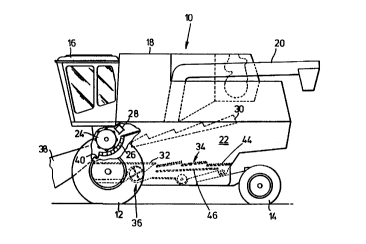
Figure 1 shows a harvesting machine 10 in the form of an agricultural
combine that is supported on forward driven wheels and rear steerable wheels 12
and 14. The harvesting machine 10 is provided with an operator's cab 16 from
which it can be controlled by an operator. The present invention can be used on a
stationary threshing machine, an experimental threshing installation or the like. A
grain tank 18 is located behind the operator's cab 16. The grain tank 18 is
provided with an unloading auger 20 for unloading clean grain from the tank. Thegrain tank 18 is supported on a frame 22.
A harvested crop is directed by feederhouse 38 past stone trap 40 to a
transverse threshing cylinder 24 and ~ssoci~ted concave 26. The threshed crop is
21 69986
.
~hen directed by beater 28 to straw walkers 30. Grain and chaff falling from theconcave 26 and the straw walkers 30 is directed to grain pan 32. The grain pan 32
in turn directs the grain and chaff to cleaning shoe 34. The cleaning shoe 34
comprises a series of sieves 44 and chaffers 46 through which air is blown by
5 blower 36. In the cleaning shoe 34 the grain is separated from the chaff and the
clean grain is directed to the grain tank 18. The lighter chaff is blown out the rear
of the combine by the blower 36. The heavier straw components are thrown out
the rear of the combine by the straw walkers 30. The harvesting machine 10 can
be a conventional combine as illustrated in Figure 1, or a rotary combine, or a
10 combine having another configuration.
Harvesting machine 10 is provided with adjustment devices, not shown, for
the controlling of the gap between threshing concave 26 and cylinder 24, the
circumferential speed of the threshing cylinder 24, the width of the opening of the
sieves in the cleaning shoe 34, and the air flow delivered by the blower 36. These
15 adjustment devices are provided with electrically conl,oll~d servo motors and are
used to operate the harvesting machine 10 at optimum conditions. Optimum
operation of the harvesting machine 10 is understood to require adjustments withwhich the harvested crop is processed and separated into its individual components
(clean grain, straw, chaff) in such a way that the highest possible output per unit of
20 area, a maximum amount of clean grain, is obtained. In order to attain this
optimum operation a certain relationship must be maintained between the
mechanical processing of the crop (threshing), the width of the sieve opening, and
the blower output depending upon the crop variety, condition of crop, degree of
cleanliness, vehicle speed, slope inclination and other factors. Since the
25 afore",entioned conditions can often change even in a single field, it is necessary
to change the current adjustments to comply with the current conditions.
Air flow through the cleaning shoe is fundamentally controlled by the
rotational speed of the blower 36. Air flow represents a significant factor in
determining cleanliness of the grain, and in determining grain losses. The
30 illusl,ated embodiment concentrates on varying the rotational speed of the blower
36. For this purpose, the blower 36 is driven by an infinitely variable belt drive, not
shown, that is adjusted by an eledric motor.
2 1 699û6
The speed of the blower is controlled by an adjusting signal. By
automatically controlling the speed of the blower, the mass of the crop located on
the cleaning shoe 34 experiences an optimum separation into clean grain and
chaff, thereby achieving a high degree of cleanliness and low grain losses.
Sensors 48 are arranged, as shown in figure 2, beneath chaffer 46. These
sensors maybe formed in a rod-shaped configuration and arranged in such a way
that they generate signals that correspond to the mass of crop falling through
openings in the chaffer 46. For this purpose at least two, but preferably a multitude
of sensors 48 are arranged in the direction of the crop flow. It is advantageous if
the sensors 48 encompass a significant part of the width of the crop flow. Thesesensors 48 are connected by cables or through radio signals to at least one
computer.
Deviating from or in addition to this embodiment, similar sensors 48 may
also be provided at other locations that underlie the crop flow, for example, under
the threshing concave 26 and/or under the straw walkers 30.
Sensors 48 detect the mass of clean grain falling from chaffer 46. The
amount of clean grain is dependent upon the air flow delivered by the blower 36
and the size of the openings in the chaffer 46. Grain loss sensors of known design
may be provided at the end of the cleaning shoe 34 in order to establish the ideal
function 50 and which transmit a qualitative signal for the mass of the grain that the
harvesting machine 10 leaves on the ground. It should be noted, that the invention
does not have the goal of determining the grain losses, but that the grain loss
sensors are intended to simplify the task of finding an Gpli",al adjustment in the
establishment of the ideal function. For the operation of the harvesting machine 10
grain loss sensors are not required once the ideal function 50 has been defined.Moreover for the initial establishment of a necessary series of
measurements the proportion of the so-called carry-over can be determined. In
addition, for the determination of the exact grain losses a counting and weighing of
the grain on the ground can take place, which can be performed in addition to ori"stead of the evaluation by the grain loss sensors.
After the sensors 48 have been installed and connected to a corresponding
computer, the harvesting machine 10 is put into threshing operation. During the
21 69~86
~reshing operation a multitude of measurement data sets are generated from the
signals of the sensors 48 while maintaining an ideal adjustment, so that a
relationship can be established between the mass of the grain passing through the
cleaning shoe and its variation over the length of the chaffer, which could appear
5 graphically as illustrated in figure 3. As can be seen in figure 3, the trend of the
curve, which is a graphical representation of the ideal function 50, results from a
multitude of supporting points each of which represents the measured value of a
multitude of sensors 48. This relationship can be expressed mathematically as the
ideal function 50 and is identified by function characteristics that remains constant
10 under all harvesting conditions with a particular location of inflection points, a
particular slope and a particular position of the maximum point.
In order to more easily manipulate the ideal function 50, a summing function
52 is generated for it, which can be expressed by the equation:
Y=A*e(s^h) where h = e(C x)
In figure 4 the ideal function 50 is the lower curve and the summing function
52 is the upper rising curve. The ideal function 50 represents an ideal cleaningfunction and the summing function 52 represents a summing cleaning function.
In the summing function 52, whose generation is not necess~ry but is
advantageous for the further processing, the symbols represent:
Y the mass of the crop as detected screened through the chaffer 46;
X the screening length, that is, the length of the path covered by the
crop along the cleaning shoe 34, in particular on the chaffer;
A a coerricie"l that has a relationship to the entire throughput of grain
through the harvesting machine 10;
B,C coeffficients that have a relationship to the rotational speed and thereby to
the output of the blower 36.
According to the typical ideal function 50 or its graphical representation as a
30 curve, this has its maximum approximately at the transition between the first third
and second third, and flattens out in the last third. In the summing function 52 this
region is characterized by the largest increase. When the entire mass flow is
21 69986
Increased, it is shown by a change in the coefficient A, the characteristic shape of
the curve of the function does not change, but only its position in the diagram.It should be noted that the ideal function so determined is valid for
harvesting machines of the same design while for harvesting machines of other
designs other ideal functions are valid.
Preferably the deter",i.,ation of the coerficienls of the summing function 52
from a measured distribution of material is programmed as algorithm in a computer
program and the computer program is supplied as input to a computer. Although itis possible to integrate the algorithm into hardware, in the present embodiment a
software solution is preferred since this can be maintained more easily and is more
flexible for future operating conditions. The computer is instal'ed as small
computer in the region of the operator's cab 16. However, it is also possible totransmit the corresponding data wireless by radio to a remote computer which canbe operated from the operator's cab 16.
The computer is equipped with an operating unit with which particular
threshold values can be controlled and from which guidelines can be derived, such
as allowable grain losses, control limit values, volume of throughput, vehicle speed
and the like. As a rule allowable values can be controlled from the outside and are
represented as threshold values.
The sensors 48 are connected to the input of the computer which accepts
the signals resulting from the mass of the grain cleaned by the chaffer 46 wherethese may be digitized either inside or outside the computer. The computer is
preferably a programmable small computer. However, a simple conventional
analog or digital summing device or the like may be used instead. In distributedmeasurement intake systems, instead of a single computer, a master-slave
computer combination could be used.
The computer or, if applicable, the master computer has a control output
leading to the drive of the blower 36 and through a co"esponding output signal
may increase or decrease the rotational speed of the blower 36.
Since the curve according to the ideal function 50 as well as that according
to the summing function 52 are known on the basis of the prior determinations inits qualitative characteristics, which are described for the course of the summing
21 69986
~unction 52 by the coefficient B and C, a momentary curve defined by all sensor
measurement values at a particular point in time or the actual course of the
function can be transmitted to the algorithm for the determination of the
coefficients, which calculates the coefficients A, B and C for the momentary curve.
The momentary coeffcients B and C are now actual values, which can be
compared with the control input (known coemcients B and C), in order to control a
control deviation. An operator may intervene here by changing the allowable
deviations of known coefficients B and C whereby the changed process conditions
are tolerdted more or less strongly. Due to the possibility of esli",dling the curve
from a few support points, considerably more sensible characteristics are given
with the coefficients B and C compared to the loss measurement afflicted by
~neasur~",ent errors, at a time earlier than with a loss measurement a goal-directed
intervention is possible and all quality characteristics of the cleaning process (loss,
cleanliness, carry-over load) can be affected. The coefficient A thereby remainsvariable since it is dependent purely on throughput. If a variation of the momentary
function from the ideal function can no longer be conl,.lled by the blower (or in the
sieve gap) or if this type of control is not desired, then another approximation,
although a somewhat coarser approximation, to the ideal function can be
performed by a change in the throughput.
Herein lies the basic difference from the conventional control system, which
initially measure the grain losses in absolute terms. The grain loss, however, is
only of subordinate interest, since it gives only a limited picture of the current load
on the harvesting machine 10 and the measurement of the grain loss is highly
error-prone.
According to the process under the invention there is a constant comparison
between the optimum and the current shape of the curve, that is, the ideal and the
actual shape of the curve, over the comparison of the mathematically, according to
the algorithm, determined values. The shape of the curve here is understood to be
the totality of the measured values of a cycle of data acquisition which can be
represented in its simplest form in the two-dimensional representation in a curve in
a diagram. During the calculation of the control differential the shape of the curve
is formed by process~hle data. Since a change in the parameter -A- has no
2 1 69986
suhstarltial effect on the peculiarities of the curve or the function, but only on its
position, when there is a deviation of the actual values from the target values a
change may be limited to its effect upon the coeffficients -B- and -C-. Since the
coefficients -B- and -C- each for itself, but also in a mathe",alical relation to each
5 other, either as product or as sum, have a relationship to the output of the blower
36 (or to the result of the cleaning operation) these can be changed by means ofan adjustment signal from the computer to the infinitely variable belt drive of the
blower and thereby the course of the actual function may be changed to comply
more closely to the course of the ideal function 50. Through a further comparison
10 performed shortly thereafter it could be established whether the direction of the
change in the blower output has led to the desired result; this is not absolutely
necess~ry, since the result of the comparison between the target and actual values
contains the direction not the amount of the necess~ry change to the blower. This
correcting variable in one direction remains active until the blower rotaliGnal speed
15 has changed so much that the resulting shape of the actual function has againapproached the shape of the ideal function 50 - whereby the comparison of targetminus actual comparison has the result of zero, which then signifies "zero" direction
(that is, a rest condition). This results in an independence from the adjusting
characteristic of the blower 36; however, in subsequent algorithms safety inquiries
20 must be made, if the controller does not have a stop.
From the comparison of target value (from which the control value was
derived) and actual value (when this is a necessarily modified control value) the
control deviation is formed (xv,= actual - target) Xwis the input signal of the
controller, which forms a control value. The control value is (modified and
25 amplified, if necessary) the intrusion into the process in order to close the control
loop.
It should be noted that for various values of throughput, if applicable also formeasurement errors or other effects there are a number of the ideal function 50
curves of equal shape, where a part of the coerficients B, C describes the series of
30 courses of ideal function only their form and not or very little in the throughput.
Then the series of functions is associated with a corresponding series of
coefficients that can be separated into varying coefficients for all functions and
21 69~86
`ralmost) constant coefficients in all functions of the series. A constant coefficient is
a machine constant once determined that remains equal over all conditions and
grain varieties at optimum operating quality.