Note: Descriptions are shown in the official language in which they were submitted.
~7~9~
BPCL Case 8578fB300(2)
APPARATUS AND PROCESS FOR POLYMERISING OLEFIN
IN GAS PHASE
The present invention relates to an apparatus and to a process for gas-phase
polymerization of olefin(s) in a fluidized and optionally mechanically stirred bed,
particularly with a device improving the drawing offofthe polymer m~nllf~ct-lred.
It is known to polymerize one or more olefins in the gaseous phase at a
s pressure which is higher than atmospheric pressure in a reactor with a fluidized bed
and a vertical side wall, where polymer particles being formed are kept in the
fluidized state above a fluidization grid by virtue of a reaction gas mixture
cont~ining the olefin(s) to be polymerized and travelling according to an upwardstream. The polymer thus manufactured in powder form is generally drawn off
0 from the reactor by at least one side discharge conduit situated along the vertical
wall of the reactor above the fluidization grid and is then subjected to a
decompression and deg~csin~ stage. The reaction gas mixture leaving via the top of
the fluidized-bed reactor is returned to the base of the latter under the fluidization
grid through the intermediacy of an external circulation conduit provided with a5 compressor. While being returned, the reaction gas mixture is generally cooledwith the aid of at least one heat exchanger provided in the external circulationconduit so as to remove the heat produced by the polymerization reaction. The
polymerization is carried out in the presence of a catalyst or of a catalyst system
introduced into the fluidized bed. High-activity catalysts and catalyst systems,20 which have been known already for a number of years, are capable of producinglarge quantities of polymer in a relatively short time, thus avoiding a stage ofremoval of the catalyst residues in the polymer.
When the polymer is drawn from the reactor, it is found to be accompanied
by the reaction gas mixture present under pressure in the reactor. It has been
25 observed that the proportion of the reaction gas mixture accompanying the
2`~1)0g~
polymer which is drawn offis generally high. This makes it necessary to provide
large-sized devices for decompressing and deg~sing the polymer which is drawn
off, and an appropriate and costly device for recovering and recompressing the
reaction gas mixture drawn offwith the polymer and for recycling most of this gas
s mixture into the polymerization reactor. Such devices generally include a lock
hopper for polymer recovery, connected to the side wall of the fluidized-bed
reactor by a draw-off conduit fitted with an isolation valve. The lock hopper may
also be connected to a decompression and deg~sing chamber by a discharge
conduit, itself fitted with an isolation valve. In most cases the draw-offconduit
0 leaves the side wall of the reactor in a direction that is perpendicular to the said
wall7 that is to say in a horizontal plane. It then reaches a lock hopper either while
still ~e~ g in the same horizontal plane, as described in US Patent
No. 4 003 712, French Patent No. 2 642 429 or European Patent No. 188 1257 or
while descending vertically after having formed an elbow7 as described in European
Patent No. 71 430. The draw-offconduit may also leave the side wall ofthe
reactor while being directed downwards and while forming a relatively small angle
with a horizontal plane, for example an angle of 18 as shown in Figure 1 of French
Patent No. 2 599 991, and next reach a lock hopper while descending vertically
after having formed an elbow. It has been observed that7 in all cases7 the proportion
of the reaction gas mixture accompanying the polymer which is drawn offis
relatively high and results in the above-mentioned disadvantages. To solve this
problem7 European Patent No. 71 430 proposes to use a separator for polymer
recovery comprising a vent conduit system comprising a valve and connecting the
said separator to the fluidized-bed reactor at a point situated above the draw-off
2s conduit near to the top of the fluidized bed for venting back to the reactor the gas
separated from the polymer in the separator. The same proposal is disclosed in
French Patent N 2 164 500 for drawing offa catalyst from a fluidized bed reactor
in a fluidized catalyst cracking (FCC) process. A mixture of fluid and catalyst is
drawn from the bottom of the reactor into a separator which is located below thelevel of the reactor and wherein the fluid is separated from the catalyst and isrecycled from the separator into the upper part of the reactor near the top of the
fluidized bed via a vent conduit provided with a valve.
An apparatus and a process for gas-phase polymerization of olefin(s) have
now been found which make it possible to avoid the above-mentioned
disadvantages. In particular, they make it possible to draw offin an extremely
- 2170098
simplified and efficient manner a polymer m~n~lf~ctured in a fluidized and
optionnaly stirred bed reactor? considerably reducing the proportion of the reaction
gas mixture drawn offwith the polymer, while avoiding blocking the draw-off
system and avoiding using a vent conduit system as disclosed in the above-
s mentioned Patents.
The subject of the present invention is first of all an appal alus for gas-phasepolymerization of olefin(s), comprising a fluidized and optionally mechanically
stirred bed reactor with a vertical side wall, provided at its base with a fluidization
grid, a conduit for external circulation of a reaction gas mixture connecting the top
o of the reactor to the base of the latter under the fluidization grid and including a
compressor and at least one heat exchanger, and at least one conduit for drawingoffpolymer provided with an isolation valve and connecting the vertical side wall
of the reactor to a lock hopper equipped with a discharge valve, apparatus
characterized in that the draw-offconduit leaves the vertical side wall of the
reactor while being directed downwards,so that each part ofthe said conduit forms
with a horizontal plane an angle A ranging from 3 5 to 90.
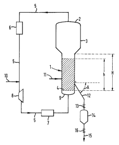
Figure 1 shows diagrammatically an apparatus for gas-phase olefin
polymerization, including particularly the device for drawing offpolymer according
to the present invention.
Figures 2, 3 and 4 show diagrammatically alternative forms of the draw-off
device of the apparatus according to the present invention.
Figure 5 shows diagl alnlllalically an apparatus which is identical with that
shown in Figure 1 and including some p~erell ed additional devices.
Figure 6 shows diagrammatically the stages for drawing offthe polymer
according to the process of the present invention.
Figure 7 shows diagrammatically the stages for drawing offthe polymer
according to an alternative form of the process of the present invention.
The apparatus of the present invention includes particularly a conduit for
drawing off polymer, which is directed downwards in order to connect the vertical
side wall of the reactor to a lock hopper, and every part of which forms with a
horizontal plane an angle A ranging from 35 to 90, preferably from 40 to 90 and
in particular from 45 to 90 or from 50 to 90. The draw-off conduit thus does not
comprise any horizontal portion nor any slightly inclined portion forming with ahorizontal plane an angle that is, for example, smaller than 35.
In the present definition an angle A is intended to mean any acute or right
0 9 8
angle that the lengthwise axis of the draw-off conduit forms with a horizontal
plane, this applying to every portion of the conduit ranging from the vertical side
wall of the reactor to the lock hopper. If a portion of the draw-off conduit (12c)
such as shown diagrammatically in Figure 4 forms an obtuse angle with a
horizontal plane? in this case the obtuse angle A'3, it will be considered that,according to the present definition, the angle A shall be the smaller angle, that is to
say the acute angle supplementary to the obtuse angle, in this case the acute angle
A3, supplementary to the obtuse angle A'3.
The draw-offconduit may consist of a single rectilinear conduit (12) such
as shown diagrammatically in Figure 2, or of a joined succession of two or a
number of rectilinear conduits (12al 12b, 12c) such as are shown diagl an~ alically
in Figures 3 and 4, it being possible for the joined part(s) between two rectilinear
conduits to be one or more portions of a curved conduit.
At the point of departure where the draw-offconduit leaves the vertical
side wall of the reactor, the initial angle A which the conduit forms with a
horizontal plane may assume any value such as that mentioned above with the
exception of 90. The initial angle, A, is thus smaller than 90, preferably notgreater than 85 and in particular not greater than 80. It may assume any valueranging from 35 to a value that is smaller than 90, p,erel~bly ranging from 40 to
85 and in particular from 45 to 80 or from 50 to 80.
The fluidized bed may occupy the whole of the reactor with a vertical side
wall, a reactor which rises to a height H starting from the fluidization grid. In this
case the point of departure where the draw-off conduit leaves the vertical side wall
of the reactor may be situated at any level of the said wall above the fluidization
grid. In practice the fluidized bed generally occupies only a portion of the fluidized-
bed reactor, so that the height of the fluidized bed, h, is equal to 0.95 ' H,
preferably 0.90 ' H and in particular 0.85 ' H, thus avoiding excessive en~ ments
of polymer particles out of the reactor. In this case the point of departure of the
draw-off conduit may be situated at any level of the vertical side wall of the reactor
above the fluidization grid, ranging up to O.9S ' H, preferably 0.90 ' H and in
particular 0.85 ' H. In practice it is preferred that the point of departure should be
situated at any level of the vertical side wall of the reactor above the grid, ranging
from 0.05 ' H to 0.95 ' H, preferably from 0.05 ' H to 0.90 ' H and in particular
fromO.1 'HtoO.85 'H.
It is preferred to employ very particularly a draw-offconduit consisting of
2170098
two joined portions of rectilinear conduit (12a, 12b) such as those shown
diagrammatically in Figure 3 . The first portion of the conduit leaves the vertical
side wall at an initial angle, A, as described above, preferably ranging from 45 to
75, and in particular from 50 to 70. The second portion of the conduit, joined to
s the first for example by a curved portion, is vertical (A = 90).
The draw-off conduit has an internal diameter that can range from 25 to
200, preferably from 50 to 150 mm, which generally depends on the di~metçr of
the polymer particles to be drawn offfrom the reactor. The internal diameter is
preferably constant from one end to the other of the draw-off conduit. The internal
0 volume ofthe draw-offconduit (V1) may be between lt2 and 1/500, preferably
between 1/5 and 1/200, in particular between 1/10 and 1/100 the internal volume of
the lock hopper (V2).
The draw-offconduit is provided with an isolation valve which is preferably
a valve with a spherical core and in particular a nonrestricted passage, which
generally has a flow opening of a diameter that is close to or identical with the
internal diameter of the draw-off conduit. The isolation valve is preferably of a fast-
opening type operating, for example, at an opening speed of less than 1 or 2
seconds. The isolation valve is preferably situated near the lock hopper, so that
the internal volume of the portion of the conduit from the vertical side wall of the
reactor to the isolation valve is substantially identical with V1.
The lock hopper is preferably a closed vessel into which the draw-off
conduit provided with the isolation valve opens in its upper part, preferably at its
top. It may, in particular, comprise in its lower part, preferably in its lowest part, an
opening provided with a discharge valve communicating with a decoll.plession anddeg~.~sing chamber through the intermediacy of a connecting conduit. The internal
volume ofthe lock hopper is preferably between 1/10 and 1/3000, in particular
between 1/100 and 1/2000 the internal volume of the reactor with the vertical side
wall.
One of the advantages of the present invention is that the lock hopper does
not need to be provided with a vent conduit system connecting the lock hopper tothe upper part of the reactor. Thus, the lock hopper preferably does not comprise
any vent conduit connecting the said lock hopper to the upper part of the fluidized
and optionally stirred bed reactor near to the top of the bed.
Figure 1 shows diagrammatically in illustration of the apparatus for gas-
phase polymerization of olefin(s) according to the present invention. The apparatus
- 217~098
includes:
(i) a cylindrical reactor (1) with a fluidized bed and vertical side wall,
provided with a top (2) and a base comprising a fluidization grid
(4),
(ii) an entry chamber (9) for a reaction gas mixture, sihl~te~ under the
grid (4) and communicating with the reactor (1) through the
intermediacy of the grid (4),
(iii) a line (11) for introducing a catalyst opening through the side wall
ofthe reactor (1),
0 (iv) an external conduit (5) for circulation of the reaction gas mixture,
connecting the top (2) of the reactor to the entry chamber (9) for
the reaction gas mixture and including a compressor (8) and at least
one heat exchanger (6, 7), and
(v) at least one conduit (12) for drawing offpolymer, provided with an
isolation valve (13), connecting the vertical side wall ofthe reactor
(1) to a lock hopper (14), the conduit (12) leaving the vertical side
wall ofthe reactor (1) while being directed downwards, so that
every part of the said conduit forms with a horizontal plane an angle
A ranging from 35 to 90, preferably from 40 to 90, in particular
from 45 to 90 or from 50 to 90.
In its lower part? the lock hopper (14) preferably comprises a discharge
conduit (15) provided with a discharge valve (16) which may be identical with the
isolation valve (13).
The reactor (1) may advantageously have above it a c~lming or
25 disengagement chamber (3) capable of reducing the ~nl~ain~lent of the polymerparticles out of the reactor, the top of the chamber (3) forming the top (2) of the
reactor.
One or more feed conduits (10) for constituents ofthe reaction gas
mixture, such as one or more olefins, for example ethylene or propylene or C4 to30 C1o alpha-olefins, one or more, preferably unconjugated, dienes, hydrogen, and
one or a number of inert gases such as nitrogen or at least one C 1 to C6, preferably
C2 to Cs alkane, may emerge into the external circulation conduit (5).
Figures 2, 3 and 4 show diagrammatically alternative forms of the draw-off
device as shown in Figure 1 and employing the same references. Figure 2 shows
3s particularly a draw-offconduit (12) consisting of a single rectilinear conduit
~17~09~
connecting the vertical side wall ofthe reactor (1) to the lock hopper (14). In
Figure 3, the draw-off conduit consists of a joined succession of two rectilinear
conduits (12a, 12b) which have respectively an angle A1 and a right angle A2. InFigure 4 the draw-off conduit consists of a joined succession of three rectilinear
s conduits (12a, 12b, 12c) which have an angle A1, a right angle A2 and an angle A3
respectively.
Figure 5 shows diagl~llullatically a ple~lled and improved alternative form
of the apparatus as shown in Figure 1 and employing the same references. It shows
particularly a feed conduit (17) for a purging gas, opening into the draw-off
0 conduit (12). The conduit (17) comprises a valve (18) for interrupting the purging.
It opens at any point of the conduit (12) situated between the point of departure
where the said conduit leaves the vertical side wall ofthe reactor (1) and the
isolation valve (13). It preferably opens near the valve (13) so as to enable the
conduit (12) to be purged at will, since the purging gas prevents the deposition and
the accumulation of polymer in the said conduit during an excessive period that
could result in the partial or complete blocking of the said conduit due to
agglomeration and possibly melting of the polymer particles. Since the isolationvalve (13) is closed at the time ofthe opening ofthe valve (18), the purging gasescapes through the conduit (12) up to the reactor (1).
Figure 5 shows furthermore an additional device allowing the polymer to be
transferred from the lock hopper (14) into a decompression and degassing chamber(19) through the intermediacy ofthe discharge conduit (15). The chamber (19) is
capable of separating the polymer from the reaction gas mixture drawn offwith it.
The separated polymer is discharged out ofthe chamber (19) by a conduit (20)
preferably provided with a valve (21), in order to be next treated or subjected, for
example, to additional degassing, and/or to be stored or gr~n~ tecl. The reaction
gas mixture separated offin the chamber (19) is discharged out ofthe latter and is
recycled into the external circulation conduit (5) by virtue of a recycling conduit
(22) provided with a compressor (23).
Another subject of the present invention is a process for continuous gas-
phase polymerization of olefin(s) in a reactor with a fluidized and optionally
mechanically stirred bed and with a vertical side wall at an absolute pressure P1
higher than atmospheric pressure, by continuous or intermittent introduction of a
catalyst into the reactor, continuous introduction of olefin(s) into a reaction gas
mixture passing continuously through the reactor according to an upward stream
~170098
and being recycled to the base of the reactor, removal of the heat of polymerization
by cooling the recycled reaction gas mixture, and drawing offthe polymer
rn~nl-f~ctllred into a lock hopper provided with a discharge valve and connected to
the vertical side wall of the reactor by a draw-off conduit equipped with an
isolation valve, process characterized in that all flow ofthe polymer drawn offby
the draw-off conduit from the vertical side wall of the reactor into the lock hopper
is produced according to a direction pointing downwards and forming with a
horizontal plane an inclination with an angle A at least equal to the angle of repose
b of the polymer and not exceeding 90.
0 The angle of repose, b, of the polymer is that defined by F.A. Zenz and
D.F. Othmer in "Fluidization and Fluid-Particle Systems" published in "Reinhold
Chemical Engineering Series" by Reinhold Publishing Corporation, New York,
(1960), pages 85 to 88. It is also called "angle of repose a" by the European
Handling Federation, Section II, Continuous Handling/Special Characteristics of
Bulk Products Transported in Pneumatic Conveyors" (FEM 2, 481), GB edition
1984, pages 9 and 10, and Figure 2.
The angle of repose b of the polymers m~nllf~ct~lred according to the
present process, in particular of powders of polyethylene, of polypropylene or of a
copolymer of ethylene or of propylene, can generally have a value higher than 30
and lower than 60, preferably ranging from 35 to 55, in particular from 40 to 45.
The process of the invention is very particularly suitable for polyolefin
powders, especially of linear low density polyethylene or high density polyethylene,
for example of density ranging from 0.87 to 0.97 g/cm3, or of polypropylene. Thepolymers m~n~lf~ctured according to the present process may particularly be
powders corresponding essentially to type B and sometimes to types A and B,
according to the classification given by D. Geldart in "Gas Fluidization
Technology" published in " Wiley-Interscience Publication" by John-Wiley & Sons
(1986), pages 33 to 46. The polymers may consist of particles which have a mass-average diameter ranging from 300 to 2000, preferably from 500 to 1500 mm.
According to the present invention, all flow ofthe polymer drawn offfrom
the reactor into the lock hopper is produced according to a downward inclinationforming with a horizontal plane an angle A that is at least equal to the angle of
repose b of the polymer and not exceeding 90, preferably ranging from b + 5 to90, in particular from b + 10 to 90. Thus, at no time from its being drawn off
from the reactor to the lock hopper will the polymer flow according to a horizontal
~1 7UOY~
plane or according to a low inclination forming with a horizontal plane an anglewhich is, for example, smaller than the angle of repose b of the said polymer.
At the point of departure of the polymer flow, where the polymer leaves the
vertical side wall of the reactor in order to flow towards the lock hopper, the angle
A of the initial inclination of the flow may assume any value equal to or higher than
b, or b + 5 or b + 10, but lower than 90, for example not exceeding 85,
preferably not exceeding 80. The angle A of the initial inclination of the flow may
thus assume any value ranging from b to a value lower than 90, preferably ranging
from b + 5 to 85 and in particular from b + 10 to 80.
o By virtue of the greatly and perpetually inclined flow type, it has been
observed that at the moment of the opening of the isolation valve bringing the
reactor into communication with the lock hopper, for example at an initial absolute
pressure P2 lower than P 1, the discharge valve of the lock hopper being closed, the
portion of the draw-off conduit upstream of the isolation valve, that is to say
between the reactor and the isolation valve, is substantially filled with polymer
which then, under the effect of the pressure difference, flows immediately into the
lock hopper according to an essentially dense-phase mode, in a first stage, until an
absolute pressure substantially equal to Pl is obtained in the lock hopper, and
which next continues in a second stage to flow into the lock hopper according toan essentially gravity mode for a sufficient time to fill the lock hopper with the
desired quantity of polymer, the said quantity being next isolated in the lock hopper
by closing the isolation valve and recovered out of the lock hopper on opening the
discharge valve.
Thus, by virtue of the strong and perpetual inclination of the polymer flow
between the reactor and the lock hopper, the portion of the draw-off conduit
upsll eam of the isolation valve is filled with polymer at rest before the opening of
the isolation valve, with the result that, when the latter opens, it is essentially
polymer in a dense phase that enters the lock hopper during the first stage and not
essentially the reaction gas mixture as in the known former processes. In addition,
when equalization of the pressure is substantially established between the lock
hopper and the reactor, generally in 1 or 2 seconds after the opening of the
isolation valve, the strong and perpetual inclination of the polymer flow promotes,
in the second stage, an essentially gravity flow mode which remains intense in the
draw-off conduit, despite an opposite current of gas escaping from the lock hopper
up to the reactor in step with the lock hopper becoming filled with polymer.
~170Ug~
The various types of solid flow mode in a gas, for example as dense phase,
concurrent or countercurrent, are defined especially by F.A. Zenz and D.F. Othmer
in "Fluidization and Fluid-Particle Systems", published in Reinhold Chemical
Engineering Series" by Reinhold Publishing Corporation, New York (1960), pages
s 477 to 487, and by J.F. Davidson and D. Harrison in "Fluidization", published by
~r.?~dçmic Press Inc., London (1971), pages 1 to 9.
It has been observed that the mean degree of filling of the lock hopper
according to the present invention is improved by at least 20 %, preferably by at
least 30 %, when compared with the known former processes.
0 It is surprising to find that the process of the invention does not lead to
partial or complete blocking of the draw-off conduit when the polymer is
particularly at rest in the said conduit just before the opening of the isolation valve
and that it flows as dense phase as soon as the said valve is opened, it being known
that the polymer drawn offfrom the reactor contains active catalyst species, that it
is still in contact with the uncooled reaction gas mixture and that the
polymerization reaction is strongly exothermic.
The polymer may be drawn off according to a cycle of operations which is
repeated during the polymerization process in a regular or irregular manner,
preferably with the aim of m~ inillg the bed of the reactor at a substantially
constant height in the reactor. By way of example, a cycle of operations is as
follows.
At the beginning of the cycle, the isolation and optionally the discharge
valves being closed, an absolute pressure P2 prevails in the lock hopper which is
empty of polymer, P2 being lower than the reactor pressure P1 . The ratio P1 :P22s mayrangefrom5:1to50:1,preferablyl0:1to25:1.TheabsolutepressureP2is
generally slightly higher than the ambient atmospheric pressure and may, for
example, range from 0.11 to 0.2 MPa, preferably from 0.11 to 0.15 MPa.
The cycle may next comprise the opening of the isolation valve, preferably
at a high speed, for example in less than 1 or 2 seconds, the discharge valve of the
lock hopper being closed. The isolation valve may be kept open for a sufficient
time to recover the desired quantity of polymer in the lock hopper, for example for
a period of 1 to 120, preferably of 2 to 40, in particular of 3 to 20 seconds. Closing
of the isolation valve may take place after an absolute pressure which is
substantially equal to the absolute pressure P 1 of the reactor has been obtained in
3s the lock hopper. Immediately or very rapidly after the closing of the isolation valve
~170098
the discharge valve is opened, preferably according to a high speed, for example in
less than 1 or 2 seconds, in order to discharge the polymer out of the lock hopper.
The polymer may, for example, be discharged into a decompression and deg~sing
chamber (19) through the intermediacy of a conduit (15) such as those shown
s diagrammatically in Figure 5. An absolute pressure P2 may prevail in the chamber
(19), which may be provided with a valve (21) in closed position at the time of
discharging the polymer from the lock hopper into the chamber, with the result that
at the end of the cycle an absolute pressure P2 is again encountered in the lockhopper.
0 The total duration of the cycle, including the discharge of the polymer out
of the lock hopper, may, for example, be from 5 to 300, preferably from 8 to 60
seconds. It is preferable that the period separating the end of one cycle from the
beginning of the following cycle should be as short as possible, for examp.le from 5
to 300, preferably from 10 to 60 seconds.
If, however, the total duration of a cycle and/or the time separating the end
of one cycle from the beginning of the following cycle are too long and create the
risk of causing partial or complete blocking of the draw-off conduit, it is preferable
to employ a purging gas, for example through the intermediacy of a conduit (17)
emerging into the draw-offconduit (12) upstream ofthe isolation valve (13) and
preferably near the said valve, as shown diagrammatically in Figure 5. The purging
gas may be the reaction gas mixture from the reactor preferably cooled, or
otherwise, one or more constituents of this mixture, hydrogen, or an inert gas such
as nitrogen or, for example, at least one C1 to C6, preferably C2 to Cs alkane, at a
pressure higher than P1. The feed conduit (17) for purging gas is provided with a
2s valve ( 18). The purging gas is introduced into the draw-off conduit upstream of the
isolation valve in order to prevent the polymer from stagnating at rest in the said
conduit when the isolation valve is closed, its introduction being preferably stopped
a sufficient time before the reopening of the isolation valve, so as to leave the
polymer the time to fill substantially the draw-offconduit. In the cycle ofthe
drawing-off operations described above by way of illustration the handling of the
valve (18) may take place in the following manner. Immediately after the closing of
the isolation valve (13) the valve (18) can be opened and can be kept open until the
beginning ofthe following cycle, just before the opening ofthe isolation valve (13).
The valve (18) is preferably closed shortly before the opening ofthe isolation valve
3s (13), for example from 1 to 30, preferably from 2 to 20 seconds before, so as to fill
~ I 7 U O J &
the draw-off conduit with polymer and consequently to promote a flow of the
polymer as dense phase through the said conduit after the opening of the isolation
valve (13). The velocity of the purging gas in the draw-offconduit may be such
that it is higher than the minimum velocity for fluidization of the polymer, or
s preferably such that it entrains the polymer out of the draw-off conduit into the
reactor.
Figure 6 shows diagrammatically the stages for drawing offthe polymer
from the reactor (1) into the lock hopper (14) through the intermediacy ofthe
draw-offconduit (12) and the isolation valve (13). In stage 6a the polymer is
0 fluidized in the reactor (1) at a pressure P 1, a portion of the polymer is at rest in
the portion ofthe conduit (12) upstream ofthe valve (13), the valve (13) is closed,
the lock hopper is empty of polymer at a pressure P2 lower than P1 and the valve(16) is open. In stage 6b the valve (16) is closed and the valve (13) is opened, the
polymer flows essentially as dense phase through the conduit (12) under the effect
e.g. ofthe pressure difference and pours into the lock hopper (14), while the
pressure in the lock hopper rises to P1. In stage 6c the pressure in the lock hopper
is equal to P 1, the polymer flows according to an essentially gravity mode through
the conduit (12) and fills the lock hopper (14), while the gas present in the lock
hopper escapes from the latter countercurrent- wise to the polymer through the
conduit (12) and returns into the reactor. In stage 6d, the valve (13) is closed, the
valve (16) is opened, the polymer present in the lock hopper leaves the latter
through the conduit (15) under the effect e.g.of a pressure difference, the pressure
in the lock hopper dropping to P2, and fluidized polymer from the reactor (1)
enters the portion ofthe conduit (12) upstream ofthe valve (13). The following
2s cycle can then recommence.
Figure 7 shows diagrammatically the stages for drawing offthe polymer
from the reactor (1) into the lock hopper (14) according to a plt;Ç~lled alternative
form employing the same references as in Figure 6, with, furthermore, a feed
conduit (17) for the purging gas and a valve (18).
In stage 7a the polymer is fluidized in the reactor (1) at a pressure P1, the
valve (13) is closed, the valve (18) is open, the purging gas moves up the conduit
(12) into the reactor and prevents the polymer from entering the conduit (12), the
lock hopper (14) is empty of polymer at a pressure P2 lower than P1 and the valve
(16) is open. In stage 7b the valve (18) is closed, polymer moves from the reactor
(1) into the portion ofthe conduit (12) upstream ofthe valve (13), where it rests.
- ~17009~
In stage 7c the valve (16) is closed, the valve (13) is opened, the polymer flows
essentially as dense phase through the conduit (12) under the effect ofthe pressure
difference and fills the lock hopper (14) while the pressure in the lock hopper rises
to P1. In stage 7d the pressure in the lock hopper is equal to Pl, the polymer flows
according to an essentially gravity mode through the conduit (12) and fills the lock
hopper (14), while the gas present in the lock hopper escapes from the latter
countercurrent-wise to the polymer through the conduit (12) and returns into thereactor. In stage 7e the valve (13) is closed, the valve (16) is opened, the polymer
present in the lock hopper leaves the latter through the conduit (15) under the
o effect e.g. of a pressure difference, the pressure in the lock hopper dropping to P2,
and the valve (18) is opened, allowing the purging gas to flush the polymer present
in the conduit (12) up to the reactor (1). The following cycle can then commence.
The isolation (13), discharge (16) and purging (18) valves are preferably
valves with a spherical core and nonrestricted passage. They can function non-
continuously, with in particular a high speed of opening and of closing produced,
for example, in less than 1 or 2 seconds. They can also function according to a
continuous movement of rotation, as described in French Patent No. 2 599 991.
The process for continuous gas-phase polymerization of olefin(s) is carried
out in a reactor with a fluidized and optionally mechanically stirred bed, ~ ed
at an absolute pressure P1 which may range from 0.5 to 6, preferably from 1 to 4MPa. The temperature of the fluidized bed may be ~n~inl~ined at a value ranging
from 30 to 130C, preferably from 50 to 110C. A reaction gas mixture passes
through the reactor at an upward velocity which may range from 0.3 to 0.8 m/s,
preferably 0.4 to 0.7 m/s. The reaction gas mixture may contain one or more
olefins, especially C2 to C1o, preferably C2 to Cg, for example ethylene or
propylene, or a mixture of ethylene with at least one C3 to C1o, preferably C3 to
Cg, olefin, for example propylene, 1-butene, 1-hexene, 4-methyl-1-pentene or
1-octene, and/or also with at least one diene, for example an unconjugated diene. It
may also contain hydrogen and/or an inert gas such as nitrogen or, for example, at
least one C1 to C6, preferably C2 to Cs alkane. The polymerization process may in
particular be carried out according to the process described in PCT Patent
Application WO N 94/28032. It may be carried out in the presence of a catalyst
comprising at least one transition metal belonging to groups 4, 5 or 6 of the
Periodic Classification of the elements (approved by the Nomenclature Committee
3s of the "American Chemical Society", see "Encyclopedia of Inorganic Chemistry",
217()0~
14
editor R. Bruce King, published by John Wiley & Sons (1994)). In particular, it is
possible to employ a catalyst system of the Ziegler-Natta type including a solidcatalyst comprising a compound of a transition metal such as those mentioned
above and a cocatalyst comprising an organometallic compound of a metal
s belonging to groups 1, 2 or 3 of the Periodic Classification of the elements, for
example an organoaluminium compound. High-activity catalyst systems have
already been known for a number of years and are capable of producing large
quantities of polymer in a relatively short time, with the result that it is possible to
avoid the stage of removal of the catalyst residues present in the polymer. These
high-activity catalyst systems generally include a solid catalyst es.senti~lly
comprising transition metal, magnesium and halogen atoms. It is also possible toemploy a high-activity catalyst comprising essentially a chromium oxide activated
by a heat treatment and used in combination with a granular support based on a
refractory oxide. The polymerization process is very particularly suitable for being
employed with metallocene catalysts such as zirconocene, haffiocene, titanocene or
chromocene, or Ziegler catalysts supported on silica for example based on titanium
or vanadium. The above-mentioned catalysts or catalyst systems may be employed
directly as they are in the fluidized-bed reactor or may be converted beforehandinto olefin prepolymer, in particular during a prepolymerization bringing the
catalyst or catalyst system into contact with one or more olefins such as those
mentioned above, in a hydrocarbon liquid medium or in gaseous phase, for exampleaccording to a non- continuous or continuous process.
The process is very particularly suitable for m~nuf~cturing polyolefins in
powder form, in particular linear low density polyethylene or high density
2s polyethylene of density ranging, for example, from 0.87 to 0.97 glcm3, or
polypropylene or copolymers of propylene with ethylene and/or C4 to C8 olefins or
elastomeric copolymers of propylene with ethylene and optionally at least one
unconjugated diene with a density ranging, for example, from 0.85 to 0.87 g/cm3.The advantages of the apparatus and of the process according to the
invention consist in remarkably increasing the degree of filling of the lock hopper
with polymer in each drawing-offoperation, while avoiding the partial or complete
blocking of the draw-offdevice. The degree of filling may, in particular, be
characterized by the weight quantity of polymer which is transferred at each
operation of drawing offfrom the reactor into the lock hopper, a quantity
3s expressed per unit of internal volume of the lock hopper: this quantity is relatively
14
~17~09~3
large and may range from 200 to 450, preferably from 250 to 400, in particular
from 300 to 400 kg/m3, it being known that these values depend greatly on the
bulk density of the polymer at rest.
The following examples illustrate the present invention.
s Example 1
A gas-phase copolymerization of ethylene with 1-butene is carried
out in apparatus which is identical with that shown diagl~"""a~ically in Figure 1. A
cylindrical reactor (1) with a fluidized bed and a vertical side wall has an internal
diameter of 3 m and a height H of 10 m and has a calming chamber (3) above it. At
its base, the reactor has a fluidization grid (4) above which there is fluidized a bed
of 18 tons of copolymer of ethylene and of 1-butene with density of 0.96 g/cm3, in
the form of a powder consisting of particles which have a mass-average diameter
of 750 mm, 90 % by weight of the particles having a diameter ranging from 300 to1200 mm. The bulk density of the fluidized powder is 300 kg/m3. The height h of
the fluidized bed is 8.5 m.
The reaction gas mixture passes through the fluidized bed at an absolute
pressure of 2 MPa at an upward velocity of 0.6 m/s and at a temperature of 92C.It contains, by volume, 30 % of ethylene, 1 % of 1-butene, 25 % of hydrogen and
44 % of nitrogen.
A catalyst of Ziegler-Natta type comprising titanium, magnesium and
halogen atoms is prepared in the form of a prepolymer in a manner which is
identical with Example 1 of French Patent No. 2 405 961. It is introduced
intermittently into the reactor via the entry line (11).
In these conditions 3.8 tons/hour of copolymer of ethylene and of 1-butene
2s are manufactured in the form of a powder which has the above-mentioned
characteristics and in particular an angle of repose, b, equal to 42.
The device for drawing offthe copolymer comprises a draw-offconduit
(12) as shown in Figure 1, which has a length of 1 m and an internal diameter of0.05 m. The conduit (12) leaves the vertical side wall ofthe reactor (1) at a height
of 1.5 m above the fluidization grid (4) in a downward direction with an initialangle, A, of 60. Midway along its length it forms an elbow and is then directedvertically (A = 90) downwards. At its lower end it has an isolation valve (13) with
a spherical core and nonrestricted passage of 0.05 m internal diameter, before
emerging into a lock hopper (14) of 105 litres internal volume, V2. In the lower3s part of the lock hopper (14) there is an exit orifice provided with a discharge valve
~170098
16
(16) communicating with a discharge conduit (15) of 0.05 m internal diameter,
connected to a decompression and deg~c~ing chamber (19) provided with a
recycling conduit (22) and a compressor (23) as well as a conduit (20) and a valve
(21), such as those shown diagrammatically in Figure 5.
The copolymer is drawn offfrom the reactor (1) according to a cycle of
operations as shown in Figure 6, including the following stages:
- the valve (13) is closed, the lock hopper (14) is empty of copolymer at an
absolute pressure P2 of 0.12 MPa, the valve (16) is open and the conduit (12)
upstream of the valve (13) is full of copolymer at rest;
o - the valve (16) is closed and the valve (13) is opened in appro~in.alely 1
second; the copolymer flows essentially as dense phase through the conduit (12)
and pours into the lock hopper (14) while the absolute pressure in the lock hopper
rises in less than 2 seconds from 0.12 to 2 MPa; the copolymer continues to flowinto the lock hopper (14) at an absolute pressure of 2 MPa according to an
essentially gravity mode, while the gas present in the lock hopper escapes
countercurrent-wise to the copolymer through the conduit (12) and returns into the
reactor (1);
- the valve (13) is kept open for 8 seconds;
- the valve (13) is closed and the valve (16) is opened in approximately 1
second; the copolymer leaves the lock hopper (14) and flows through the conduit
(15) into the chamber (19) in approximately 3 seconds, while the absolute pressure
in the lock hopper decreases rapidly from 2 to 0.12 MPa and while copolymer
enters from the reactor (1) into the conduit (12), where it rests.
The cycle ofthe operations is repeated every 30 seconds. At each cycle the
2s quantity of copolymer drawn offfrom the reactor through the intermediacy of the
lock hopper is 32 kg. The degree of filling ofthe lock hopper (14) with copolymer
is 305 kg per m3 of the internal volume of the lock hopper.
The copolymerization process takes place in this way for several days
without blocking of the draw-offdevice.
Example 2
A copolymerization is carried out which is identical with that of Example 1,
except for the fact that the apparatus employed is that shown diagrammatically in
Figure 5. Furthermore, the cylindrical reactor (1) has an internal diameter of 4.5 m
and a height H of 16 m, and a bed of 70 tons of a copolymer of ethylene and of 1-
3s butene identical with that of Example 1 is fluidized. The height h of the fluidized
16
-- ~1701)98
bed is 14 m. The absolute pressure P1 ofthe reactor is 2.3 MPa. A purging gas
feed conduit (17) provided with a valve (18) emerges into the conduit (12) just
above the valve (13). In these conditions 17.3 tons of copolymer are m~n~1f~ctured
per hour.
The device for drawing offthe copolymer is identical with that of Example
1, except for the fact that the internal diameter ofthe conduit (12) and ofthe valve
(13) is 0.075 m, the conduit (12) leaves the vertical side wall ofthe reactor (1) at a
height of 1 m above the grid (4), the internal volume (V2) ofthe lock hopper (14)
is 200 litres, the internal diameter ofthe conduit (15) is 0.0625 m, and that two
o devices of this type are installed in parallel for drawing offthe copolymer.
The copolymer is drawn offfrom the reactor (1) with the aid of the two
draw-off devices according to a cycle of operations as shown in Figure 7, including
the following stages for each of the two devices:
- the valve (13) is closed, the valve (18) is open and allows a reaction gas
mixture which is identical with that in the reactor (1) to pass through, at a
temperature of 92C at an absolute pressure of 2.4 MPa, travelling at a velocity of
0.6 m/s in the conduit (12) up to the reactor (1), preventing the copolymer fromst~gn~ting at rest in the conduit (12); the lock hopper (14) is empty of polymer at
an absolute pressure of 0.12 MPa and the valve (16) is open;
- the valve (18) is closed, fluidized copolymer enters the conduit (12)
upstream of the valve (13), where it rests;
- 8 seconds later the valve (16) is closed and the valve (13) is opened in
approximately 1 second; the copolymer flows essentially as dense phase through
the conduit (12) and pours into the lock hopper (14) while the absolute pressure in
the lock hopper rises from 0.12 to 2 MPa in approximately 2 seconds; the
copolymer continues to flow into the lock hopper (14) at an absolute pressure of 2
MPa according to an essentially gravity mode, while the gas present in the lock
hopper escapes countercurrent-wise to the copolymer through the conduit (12) up
to the reactor (1);
- the valve (13) is kept open for 10 seconds;
- the valve (13) is closed and the valves (16) and (18) are opened in
approximately 1 second; the copolymer leaves the lock hopper (14) and flows
through the conduit (15) into the chamber (19) in less than approximately 4
seconds, while the absolute pressure in the lock hopper decreases rapidly from 2 to
0.12 MPa, and while the copolymer present in the conduit (12) is flushed from the
700g8
18 - -
latter into the reactor (1) by the purging gas.
The cycle of the operations is repeated every 25 seconds for each of the
draw-off devices. At each cycle the quantity of copolymer drawn off from the
reactor through the intermediacy of each device is 60 kg. The degree of filling of
the lock hopper (14) with copolymer is 300 kg per m3 of internal volume of the
lock hopper.
The copolymerization process takes place in this way for several days
without blocking of the draw-off devices.
Example 3 (comParative)
The operation is performed exactly as in Example 1, except for the fact that
the first portion ofthe conduit (12) has an angle A of 18 instead of 60.
It is found that in each cycle of the draw-off operations the quantity of
copolymer drawn offis 30 % smaller than in Example 1. The low degree of filling
ofthe lock hopper (14) is due to the fact that before the opening ofthe valve (13)
the portion of the conduit (12) upstream of the valve (13) contains very little
copolymer and that, when the valve (13) is opened, it is essentially the reaction gas
mixture that passes through the conduit (12) and enters the lock hopper (14).
Furthermore, when the pressure equilibrium is obtained between the lock hopper
and the reactor, the flow of the copolymer through the conduit (12) takes place
slowly and finally there is relatively little filling of the lock hopper (14) with
copolymer. As a result the cycle of the operations for drawing offthe copolymer is
repeated more frequently than in Example 1, in order to ensure an equivalent
hourly output and a constant bed height in the reactor. It is observed, moreover,
that the compressor (23) intended to recycle into the conduit (5) through the
2s intermediacy of the conduit (22) the reaction gas mixture accompanying thecopolymer which has been drawn off and separated from the latter in the chamber
(19) is subjected to markedly more intensive work than in Example 1 in order to
ensure the recycling of a much larger volume of gas.
3s
18