Note: Descriptions are shown in the official language in which they were submitted.
- '~ 2 1 70 1 28
The invention relates to a device for operating switches, in
which a plurality of interlinked hydraulic switching devices
are arranged to be offset in the longitudinal direction of the
rails. In such devices for operating switches it is known to
realize the connection of the individual locks by means of a
mechanical rod assembly. However, such a mechanical connection
of a plurality of switching devices or locks requires
relatively much space as well as a great number of different
individual components. In addition to requiring more space,
such a mechanical connection impedes the ability of the tongue
means to be packed and, moreover, causes an unfavorable
unilateral mass distribution on a switch.
From EP-A2 480 303 a hydraulic switching device has already
been known, in which a plurality of individual actuating
cylinders are controlled from a hydraulic station. From DE-B2
19 52 823 different circuit arrangements for the series or
parallel connection of a plurality of such hydraulic switching
devices have been known.
The known hydraulic switching devices each reguire a separate
hydraulic drive unit, thus calling for a relatively expensive
overall structure.
The invention aims at providing a device of the initially
defined kind, which can be installed in existing switch
operating arrangements in a simple manner by way of addition
and which does not involve any expenditures for an additional
drive unit and an accordingly expensive control unit. In
particular, the invention aims at safeguarding a high degree
of reliability and non-susceptibility to failures despite a
simple mode of construction requiring only few different
structural components. Finally, the device according to the
invention is to be applicable in a simple manner as a
substitute for mechanical devices of known construction to
'- 2170128
enhance operability without increased mass.
The apparatus according to the invention provides that at
least one hydraulic cylinder/piston unit is connected with
a first mechanical switching device, the cylinder volumes
of which cylinder/piston unit(s), as pump working volumes,
are connected with the working volumes of neighboring
switching devices comprised of hydraulic cylinder/piston
units so as to be driven in same direction. By the fact
that a first cylinder/piston unit is employed as a pumping
element, expensive drive units may be obviated. In a
switching procedure, the pump unit displaces fluid from the
respective working volume into working volumes of
identically configured cylinder/piston units, thus being
able to immediately realize coupling with neighboring
cylinder/piston units. On the whole, such a device may be
assembled of identically designed cylinder/piston units of
particularly simple modes of construction with nothing but
appropriate hydraulic ducts having to be provided for the
interconnection of neighboring cylinder/piston units.
Interconnection each is effected in a manner that the
equidirectional displacement of neighboring cylinder/piston
units will be caused if medium is pressed out of the first
passive cylinder/piston unit actuated by the mechanical
switching device.
~ ~'
~ 217Q ~
Therefore, in accordance with this invention an arrangement
for operating a rail switch has a mechanical switching
device, and includes a plurality of interlinked hydraulic
switching devices separated in the longitudinal direction
of the rails and each comprising a hydraulic
cylinder/piston unit. At least one of the hydraulic
switching devices is directly connected with the mechanical
switching device, and the units have cylindrical volumes
defined by the cylinder and the piston of each respective
unit. Those volumes of respective units are hydraulically
interconnected, whereby when a piston of one of the units
is displaced relative to its cylinder in response to
displacement of the mechanical switching device (thereby
pumping fluid from one of the unit's cylindrical volumes in
accordance with the piston's displacement), the pistons of
the remaining units are displaced in the same direction.
In a particularly simple manner, the configuration
according to the invention is further developed in a manner
that the pumping element and the hydraulic switching
devices each contain in a cylinder a floating piston or a
plunger, respectively, that is guided between two working
volumes, the end or annular surfaces of the piston or
plunger each plunging into the respective opposite working
volumes having identical cross sectional areas. Such a
floating piston or plunger constitutes a structurally
particularly simple, operationally safe and compact
structural unit to be arranges on the
- 2a -
~ 21 70128
-- 3
respectively desired site while requiring little space. Theremay be provided a plurality of identical cylinder/piston units
of this type, the essential advantage being that identical
cross sectional areas are each actuated by means of a pressure
medium such that synchronous movement is obtained.
If non-linear displacement is desired, the respective cross
sectional correction may be effected with such a configuration
in a simple manner by means of sealing elements or packings in
order to ensure the respectively sought course of displacement
with the respectively displaced volume rem~; n; ng constant.
Thus, a hydraulic switching device of this kind including
floating pistons or plungers, in addition to its compact mode
of construction, also offers a simple way of adaptation to the
requirements desired in each case.
For coupling the hydraulic switching devices and the pumping
cylinder, respectively, with the mechanical switching devices,
the configuration advantageously may be devised such that the
piston or plunger of the pumping element comprises a bearing,
in particular a sliding block having an annular grove or a
bearing eye between its free ends, and that the bearing is
arranged to project from an opening of the cylinder or between
two stationarily fixed cylinders. A particularly simple and
operationally safe compact design is again feasible, which is
suitable also for subsequent installation in a simple manner.
Instead of the initially mentioned plungers or floating
pistons, the respective annular surface of a piston may ensure
the required identical working cross sections in both
directions of displacement, as already pointed out above. A
particularly simple construction in this case is provided in
that the piston is rigidly connected with a continuous piston
rod sealingly passing through the cylinders and that the
piston rod or the cylinder is stationarily fixed.
- ~ 2 1 70 1 28
In order to guarantee a high degree of safety, the overall
system advantageously is adjusted at a predetermined over-
pressure relative to atmospheric pressure. In this manner,
temperature fluctuations, which might lead to changes in
pressure, can be buffered, to which end the configuration
advantageously is devised such that the working volumes of the
cylinder/piston units are connected with a pressure reservoir
via overpressure valves. In a particularly simple manner, said
overpressure valves are designed as nonreturn valves that may
be triggered open, such controllable nonreturn valves implying
a high degree of operating safety. At high operating
temperatures medium is pressed out into the pressure reservoir
by triggering the nonreturn valves open, whereas, with the
pressure decreasing, the pressure must be made reavailable to
the system via the nonreturn valves. In order to ensure, with
such a configuration, that the operating safety continues to
- be safeguarded in case of a leakage occurring within the duct
system by warning in time, the configuration in a particularly
simple manner may be devised such that a pressure-controlled
directional control valve is each connected to the pump
working volumes, which gets into the closed position as the
pressure falls below a predetermined pressure, thus ensuring
that all of the switching devices are blocked in that case.
Blocking of the switching devices would be signalized by the
mechanical actuating drive and the pert~;n;ng control means
for the mechanical actuating drive on the respective site such
that the repair of any defect may be initiated at once.
An alternative method to cross-section changing, for
controlling a switching position differing along the rail
track is provided by a configuration which preferably is
devised such that push-open valves are arranged in a duct
connecting the two working volumes of a cylinder/piston unit
and designed, for instance, as a bore. This connection is
interrupted as a function of the position of the piston or
plunger, or there is a flow-through with the set position
being exactly assumable.
- 2 1 70 1 28
In the following, the invention will be explained in more
detail by way of exemplary embodiments schematically
illustrated in the drawing. Therein, Fig. 1 is a top view on a
section of a rail switch, Fig. 2 shows a detail of the
connection of a cylinder/piston unit including a mechanical
slide rod, Fig. 3 is a schematic partial view of the
illustration according to Fig. 2, Fig. 4 is a partially
sectioned illustration of the hydraulic cylinder/piston unit
on an enlarged scale, Fig. 5 is a top view on the illustration
according to Fig. 4, Fig. 6 is a schematic representation of
the hydraulic connection of the individual cylinder/piston
units, Fig. 7 is a modified configuration of the hydraulic
connection, Fig. 8 depicts an alternative arrangement of
hydraulic cylinder/piston units in the track extension and
Figs. 9, 10 and 11 represent further alternative embodiments
of cylinder/piston units intended for the device according to
the invention.
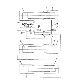
Fig. 1 schematically indicates rails 1, which are connected
with sleepers 2. In the region of a switch, tongue rails 3 are
provided in addition to the standard rails 1, which tongue
rails may be brought into the respective position by means of
an actuator schematically indicated by 4. The actuator 4 acts
on the tongue rails 3 via slide rods 5. The slide rods 5 are
coupled with a hydraulic cylinder/piston unit 7 via a central
tap 6. Furthermore, additional hydraulic cylinder/piston units
7 are visible in the rail track, each being coupled with slide
rods and locking devices, which are again schematically
indicated by 5. From the representation of Fig. 2 the type of
the mechanical connection of the hydraulic cylinder/piston
units 7 by the slide rods 5 is more clearly apparent. The
cylinder/piston units 7 each comprise a sliding block 8 in
which a pin 9 of the slide rod 5 is engaged. Upon actuation of
the slide rod 5, the sliding blocks and hence the pistons of
the hydraulic cylinder/piston units are displaced, thus
pressing medium out of the respective working volume. Fig. 3
'~ 2170128
clearly shows the type of fixation of the hydraulic
cylinder/piston unit 7 to the sleeper 2. Fixation is realized
by means of a stop plate 10 fixed to the sleeper 2. The
hydraulic cylinder/piston units 7 thereby require relatively
little space such that the packing of the substructure will
not be affected.
The mode of functioning of the hydraulic cylinder/piston units
and their preferred configuration is explained in more detail
in Figs. 4 and 5. Figs. 4 and S depict a hydraulic cylinder/
piston unit 7 comprising a plunger 11. The plungers 11 plunge
into the respective working volumes 13 of the hydraulic
cylinder/piston units via sealings 12, medium each being
pressed out of the respective working volume 13 upon
displacement of the plunger 11 in one of the directions
indicated by double arrow 14. The hydraulic connections run to
the externally provided openings 15 in the respective working
volume 13. The sliding block is again denoted by 8, effecting
mechanical coupling. A rubber sleeve 16 is provided to protect
the device.
In Fig. S the device according to Fig. 4 is visible in top
view. As can also be taken from the illustration according to
Fig. 4, equal cross sections are each effective on either side
with such a configuration of the hydraulic cylinder/ piston
unit. The fixation of the cylinders of the hydraulic
cylinder/piston units is realized on the angle plate 10 via
bolts 17.
As is apparent from Fig. 6, the working volumes 13 of the
first hydraulic cylinder/piston unit 7 acting as a pumping
element are connected with the respective working volumes 13
of neighboring hydraulic cylinder/piston units 7 via hydraulic
ducts 18, the connection being realized in a manner that, upon
displacement of the first hydraulic cylinder/piston unit,
which acts as a pumpung element, all the other hydraulic
cylinder/piston units 7 will be coupled for unidirectional
- 2 1 70 1 28
displacement. If hydraulic cylinder/piston units arranged in
parallel or in series are to follow a course differing from
that covered by the hydraulic cylinder/piston unit used as a
pumping element, the cross section must be acted upon
accordingly, to which end an appropriate sealing member may be
arranged in the interior of the cylinders to reduce said cross
section. The hydraulic ducts 18 contain a number of valves to
keep the pressure constant under operating conditions and to
be able to safely seize inadmissible situations. In detail,
there is provided a spring-loaded valve 19 actuated by the
hydraulic pressure prevailing within the ducts 18. If the
pressure within the hydraulic ducts 18 falls below a limit
value, the force of the spring of the spring-loaded valve 19
will set the spring-loaded valve 19 into the closed position
so as to avoid further displacement of the hydraulic
cylinder/piston unit 7 acting as a pumping element. In that
case, the switch actuator is blocked and an appropriate fault
message is delivered.
Furthermore, a pressure reservoir 20 is provided, which is
connected with the respective hydraulic ducts 18 via overflow
valves or nonreturn valves 21. The overflow valves or non-
return valves are switched in a manner that fluid will be
pressed into the reservoir 20 at an increase in pressure due
to thermal expansion and, vice versa, fluid will be pressed
back from the hydraulic reservoir 20 into the ducts 18 at a
slight decrease of the pressure. The spring-loaded safety
valves 19 will enter into effect only upon leakaye and a
respective pressure decrease brought about in the reservoir
20.
Fig. 7 depicts a simplified configuration of the hydraulic rod
assembly. The reference numerals from Fig. 6 have been
retained in Fig. 7. As is apparent from the simplified
configuration according to Fig. 7, a smaller number of valves
will do with equal effects being achieved. Also in that case a
pressure reservoir 20 is connected to the overall hydraulic
- _ 2170128
circuit in order to balance out oil leakages, hydraulic liquid
thus being returned into the reservoir 20 at a response of one
of the overpressure valves 21. The biassed valves or safety
valves 19 are actuated by the receiver pressure from the
piston reservoir. Overpressure may be caused, in particular,
by too strong heating-up due to sun radiation. In the
representation of Fig. 7, the piston volumes again are
connected in series, the pumping element again being provided
with biassed valves or safety valves 19. Both connection ducts
again are separately secured by means of overpressure valves.
In the representation according to Fig. 8, modified hydraulic
cylinder/piston units 7 are provided, each contacting the ends
of the slide rods 5. In principle, the modified
cylinder/piston units 7 fulfill the same purpose as the
configuration according to Fig. 1, yet the functions of
displacement to the left or to the right are separated from
each other, no common plunger or piston being employed for
both working volumes.
From Fig. 9 a modified design of the hydraulic cylinder/
piston units is apparent. Also in this case, the configuration
for the purpose of providing egual working surfaces with fluid
is devised such that equal cross sections of a piston each
become effective in the two working volumes 13. The piston 22
is connected with a piston rod 23, the annular surface each
becoming effective or being actuated in the instant case.
Moreover, the same components as in the configuration
according to Fig. 6 or 7 have been employed, the same
reference numerals having been applied again. Deviating from
the configuration according to Fig. 6 or 7, a deadlock is
caused immediately at a pressure decrease of any of the
cylinder/piston units, all of the working volumes 13 being
equipped with suitable safety valves.
In Figs. 10 and 11, the working volumes 13 of a
cylinder/piston unit 7 are interconnected by a duct 24
~ ~ 2170128
constituted by a bore, in which push-open valves 2S are
installed. These valves, if appropriately adjusted, effect the
exact course-dependent displacement re~uired, whereby the
alternately possible cross sectional changes may be obviated.
The individual displacement paths of these locks roughly may
be predetermined by defining the diameter ratios, precise
detailed adjustment being feasible via the push-open valves by
regulating the stroke of the plunger by adjustment of the
cylinder bottom relative to the push-open valve. After each
switching procedure, readjustment is effected by the reference
circuit of the push-open valves. Any displacement of a piston
due to leakages thus will be corrected by readjustment after
completion of a switching procedure.
The use of such adjustable push-open valves ensures the
hydraulic synchronism, which means that no displacement
cylinder is able to run ahead and hence no tongue distortion
can occur. Thus, the end positions of the tongue rail are
reached in a concerted manner.