Note: Descriptions are shown in the official language in which they were submitted.
i3'~ 95/05771 . . ~ ~ PC'1'lIJS94/09390
1
~EELE ~E ~LU Elu c~li E
1~
Field of the In~rantmon
This invention relates to st~erable cath~t~rs for use in a body lumen, and
more specifically to an electrode catheter having a steerable tip and an open
lumen.
l~ackgr_oun~f the Inventi~n
Electrod~ oath~ters have b~~n in common use in medical practice for
many years. They are used t~ stimulate and reap electrical activity in the
heart
and to ablate sites of ab~rrant electrical activity.
2~ in use, the el~ctrode catheter is insertod into a major v~in or artery,
e.g.,
femoral artery, and then guided into th~ chamber of the heart which is of
concern. iNithin the h~art, th~ abiiity t~ control the exact position and
on~ntation of the catheter tip is critical and larg~iy determines how useful
the
catheter is.
Steerable tip electrode catheters are no wall known. Such a catheter
generally has a control handle at its proximal end for controlling deflection
of the
tip in one or more directions. For example, tl.S. Patent No. 4,96~,134 to
applicant discloses a particularly useful steerabBe tip catheter. This
catheter
comprises a pullet wire which extends on-axis through an elongated reinforced
3~ catheter (body and then off-axis in a d~flectable tip portion. In this
arrangement,
longitudinal movement of the pullet wire reBative to the catheter body results
in
deflection of the catheter tip portion. The catheter body tends not to deflect
for
two reasons. First, it is reinforced and therefore resists compression.
Second,
the pullet wire extends coaxially within the catheter body. The compressive
forces on the cath~ter body are gen~rally uniformly distributed across the
catheter body and deflection is thereby minimized. 'This allows precise
rotational
control of the catheter body and tip.
_1_
Image
WO 95/05771 PCT/US94/09390
z1'~~~'~~
1 distal end of the pulley wire is fixedly attached to the tip portion at or
adjacent
to the distal end of the tip portion. The proximal end of the pulley wire is
o attached to the control handle for moving the pulley wire longitudinally
relative
to the catheter body and coil spring. By this arrangement, longitudinal
movement of the pulley wire relative to the catheter body and coil spring
results
in deflection of the catheter tip with minimal and preferably no deflection of
the
catheter body.
Preferably, a flexible, compressible, lubricous sleeve surrounds the pulley
wire in the tip portion. A sleeve made of polytetrafluoroethylene is presently
preferred.
In a particularly preferred embodiment of the invention, the tip portion
carries one or more electrodes, including a tip electrode. In such an
embodiment,
the first lumen extends through the tip electrode and the distal end of the
pulley
wire may be attached directly to the tip electrode. There is preferably
provided
a third lumen which extends through the catheter body and tip portion and
provides a passageway for electrode lead wires. The electrode lead wires
extend
from the electrodes carried on the tip portion through the catheter body and
control handle to one or more plugs which are electrically connected to an
electrical stimulator and/or recorder, an RF energy source or the like.
25
35
-3-
a ~~.~~~~4 , .
_ . . ~ ~ j~~'95
1 Brief Description of the Drawings
These and other features and advantages of the present invention will be
better understood by reference to the following detailed description when
considered in conjunction with the accompanying drawings wherein:
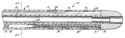
FIG. 1 is a longitudinal offset cross-sectional view of a preferred three
lumen electrode catheter constructed in accordance with the present invention,
showing all three lumens;
FIG. 2 is a transverse cross-sectional view of the catheter body of FIG.
1 along line 2-2; and
FIG. 3 is a longitudinal cross-sectional view of the proximal end of a
preferred catheter showing a fitting for the injection or withdrawal of fluid
through the open lumen of the catheter body.
FIG. 4 is a longitudinal offset cross-sectional view of another preferred
electrode catheter;
FIG. 5 is a longitudinal cross-sectional view of another ablation tip
electrode;
FIG. 6 is a longitudinal cross-sectional view of the distal end of another
preferred ablation catheter including an anchor wire;
FIG. 7 is a longitudinal cross-sectional view of the distal end of another
preferred ablation catheter including an RF antenna; and
FIG. 8 is a side view of the exterior of the catheter to show a control
handle of a type suitable for use with the catheter of the invention.
30
~if IV-t..~
-4-
Image
I~E~'7I'I~J~~~/~~3~0
~~ ~510577~ ~~ are ~~
~h~ ~th~~ ~nd ~~ t~bfing ~7J as ~~c~w~d b~ ~~~th~~ ~~~t0~~ ~~ t~hb~g ~~
e~hi~h ~a~~e ~~~ ~x~p9~a t~~~a~n~t~ ~~ ~ ~u~r hash ~~ th~ ~~~~ t~ ~~~~as~ the
o~~~ct~~~
~e ~thd~~~aa~ ~~ ~~~a6d~ t~ ~~ ~~~~ the ~~~~t ~~~~a ~ ~e ~~t~~~~to~~~~D the
~~de ~~~
~~ ~y ~~ asp~~d~d int~g~~~9y ~th the ~~th~t~P ~~d~ ~ ~o
~~~~P'sng ~ga~n t~ F6Sm ~ ~~d ~p the ~~c~~d I~~~~ ~~ ~~t~nd~ the fi~~gth
~~ th~ ~~th~t~~ ~~d~ ~ ~ end tip p~~e~~ ~ ~a ~~ the ~~~~d°s~a~~t ~h~~p
the
~~c~~d 6~~a~n ~~ his ~ d°s~a~a~t~~ ~~ ~h~~t ~o~~~ a~~h ~~d o~ ~8~~~d ~t
age de~t~~
~c~do ~c~~s~ ~~ the ~~~d ~~~ ~ ~o~~u~ di~~t~~ ~~ ~t ~~~~t ~a~~ arch ~~d
as ~a~r~-~~mp~~~s~b~~e
~
CA 02170274 2006-02-O1
loosely wound and therefore flexible and compressible. This can be accom-
plished, for example, by "stretching" the portion of the coil spring 51 which
is to
be disposed in the tip portion 14. In this embodiment, the portion of the coil
spring 48 in the catheter body 12 must still be fixedly attached, e. g. , by
glue, to
the catheter body 12 at the proximal and distal ends of the catheter body 12.
A pulley wire 36, preferably made of stainless steel, having a diameter of
about 0.006 inch is disposed within and slidably extends through the coil
spring
48 and sleeve 38. Preferably, the pulley wire 36 comprises a lubricous coating
to
prevent the pulley wire 36 from sticking to the coil spring 48. The coating is
preferably made of a material such as polytetrafluoroethylene which provides
excellent non-stick characteristics. Sleeve 38 prevents the pulley wire 36
from
"cutting through" the wall of the tip portion 14 and also provides lubricity.
The distal end of the pulley wire 36 is fixedly attached to the tip electrode
19, e.g., by weld 31 or the like. Alternatively, the pulley wire 36 may be
fixedly
attached to the outer wall of the tip portion 14. A suitable means for
attaching the
pulley wire 36 to the wall of the tip portion 14 of a deflectable catheter is
de-
scribed in U.S. Patent No. 4, 960,134.
The proximal end of the pulley wire 36 is connected to a control handle as
is well known in the art. A suitable control handle is disclosed in U.S.
Patent
No. 4,960, 134. Such a control handle can be used to effectively manipulate
the
catheter tip portion.
The third lumen 22 also extends the length of the catheter body 12 and
into the tip portion 14 and is closed at its distal end. The third lumen 22
contains
electrode lead wires 62 that are attached at their distal ends to the
electrodes
carried by the tip portion 14. The lead wires extend to the proximal end of
the
catheter body 12, through the control handle (not shown) and terminate in a
suitable plug as is well known in the art.
The coil spring is rigidly attached by polyurethane glue or the like to the
catheter body at its distal and proximal ends. Because the catheter coil
spring 48
is noncompressible, tension on the pulley wire 36 will not translate into
compres-
sive tension on the catheter body 12. The noncompressible coil spring 48
thereby
assures that the catheter body 12 does not bend as a result of tension on the
pulley
wire 36 and thereby assumes that rotational control of the catheter 10 is not
adversely affected when the pulley wire 36 is under tension. By incorporation
of
the noncompressive coil spring 48, the pulley wire 36 can be
Image
'f
1 electrode 19 may or may not also be used to deliver RF energy, as desired.
The
RF antennas 58 may be straight or have a preformed shape, as desired. FIG. 8
shows the catheter 10 with a control handle 80 at its proximal end. The
control
handle has an annular flange 84, where it meets the catheter body 1 2.
It is apparent that, if desired, an anchor wire may also be used as an RF
antenna for delivering RF energy to the endocardium.
The first lumen could be used for other applications. For example, an
optic fiber may be passed through the first lumen for viewing of or delivery
of
laser radiation to a selected site. A temperature probe may be passed through
the first lumen for monitoring temperature. In an ablation procedure, this
would
enable one, for example, to place a thermistor directly against, or even into,
the
portion of the endocardium being heated in an RF ablation procedure. This
would
enable one to monitor the temperature of the tissue being heated and control
that
temperature by controlling the intensity of the RF current being delivered to
the
tissue with more precision than current designs offer.
It is understood that the open lumen rnay perform more than one function,
e.g., contain a movable anchor wire and provide a passageway for cooling
fluid.
It is also understood that more than one open lumen may be provided, e.g., one
open lumen for passage of fluids and another for containing an anchor wire,
temperature probe, etc.
Thus, while the preceding description has been presented with reference
to presently preferred embodiments of the invention, workers skilled in the
art
and technology to which this invention pertains will appreciate that
alterations
and changes in the described structure may be practiced without meaningfully
~ departing from the principal, spirit and scope of this invention.
Accordingly, the foregoing description should not be read as pertaining
only to the precise structures described and illustrated in the accompanying
drawings, but rather should be read consistent with and as support to the
following claims which are to have their fullest and fair scope.
35
. ;NFFT
_g_