Note: Descriptions are shown in the official language in which they were submitted.
- 2170~0B
--1--
FIELD OF T~E lN V ~llON
The present invention relates to a method for
detecting malfunctions or failures in pressure
regulators used in corrosive gas distribution systems
and a method for preventing such malfunctions or
failures.
BAC~GRO~ND OF T~E INVENTION
Gas distri~ution syste~s, including inert and non-
inert gas distribution systems, are used in a wide range
of applications. Inert gases are not usually a problem
for the various parts of a gas dis~ribution system.
However, non-inert gases, i.e., gases which may have a
reaction with their environment, including reactive
gases or corrosive gases, generate several problems
related to their handling or transportation,
particularly corrosive gases which may be very
aggressive for their environment such as pipelines,
valves, pressure regulators, etc. For example,
corrosive HBr gas is used in the manufacture of
semiconductors. In many manufacturing facilities, the
corrosive HBr gas is stored in cylinders located in a
cylinder cabinet outside the manufacturing facility. A
gas distribution system is then provided to transport
the corrosive gas to the appropriate place within the
manufacturing facility.
~ 2l~u~a~
The gas distribution systems typically include many
components for gas flow control, e.g., pressure
regulators and mass flow controllers. A statistical
analysis of the origin of the failures in the corrosive
gas distribution systems revealed that these components
are the most frequent locations of malfunctions or
failures.' The general features of such a pressure
regulator valve are illustrated in FIG. 1 and include an
inlet 22, an outlet 24 and a diaphragm 26. A restricted
orifice 28 is provided in the diaphragm and defines a
seat 30. A poppet 32 biased by a poppet spring 34 and
provided with a poppet cap 40 is designed to engage the
seat 30 to thereby control or regulate the flow through
the restricted orifice 28. A pressure adjustment knob
36 connected to a load spring 38 is also provided to
effect adjustment of the pressure regulator 20.
When the pressure regulator malfunctions or fails,
it is of course necessary to replace the pressure
regulator. The malfunction or failure of the pressure
regulator, as well as the subse~uent replacement
process, can lead to undesirable cont~in~tion of the
process gas and possible failure of other components of
the system. In addition, productivity losses in the
manufacturing line inevitably result whenever a pressure
regulator malfunctions, fails or requires replacement.
Further, in some instances the malfunction or failure of
217~6
the pressure regulator can result in the leakage of
corrosive gases, thereby causing significant safety and
environmental problems.
One of the major causes of the aforementioned
malfunction or failure of the pressure regulators is the
corrosion of and/or the deposition of corrosion products
on the area of the poppet 32 at which the pressure drop
occurs (i.e., in the area of the restricted orifice 28).
Since the space between the outer surface of the poppet
32 and the seat 30 is on the order of a few microns, the
outer surface of the poppet 32 must be very smooth to
achieve proper leak tightness and to control secondary
gas flow. The presence of even a slight amount of
corrosion and/or deposition on the outer surface of the
poppet 32 can prevent achievement of the necessary lea~
tightness and can result in the occurrence of a
secondary gas leak when the regulator is in the closed
pos ltlon .
This type of internal leak in the pressure
regulator can also arise due to corrosion of the poppet
spring 34. Such corrosion can weaken the spring force
of the poppet spring 34 and thereby inhibit the poppet
32 from fully engaging the seat 30 to close the
restricted orifice 28.
In addition to the aforementioned internal leaks,
pressure regulator malfunction or failure can result
030~
from external leaks. That is, the corrosive gas flowing
through the pressure regulator can cause pitting
corrosion (i.e., tiny holes) in the diaphragm 26 of the
pressure regulator 20. This external leak can cause the
S leakage of corrosive gas directly to the surrounding
environment.
It has been found that one of the major causes of
corrosion in the gas distribution system which
contributes to the aforementloned internal and external
leaks of the pressure regulator is attributable to the
cylinder exchange process. That is, when the cylinder
containing the corrosive gas is empty, it is necessary
to replace it with a full cylinder. If proper
procedures are not followed during the replacement
process, moisture from the atmosphere can invade the gas
distribution system, there~y eventually leading to the
presence of corrosion in the lines.
To avoid the potentially serious problems that can
result from the malfunction or failure of a pressure
regulator in a corrosive gas distribution system, the
pressure regulators in the gas distribution system are
typically replaced at specified intervals of time. The
hope is that by replacing the pressure regulators at
scheduled intervals, it will be possible to avoid
situations in which the regulators fail. However, as
can be appreciated, the regulators may experience
~17~306
corrosion problems that are more significant than
expected, thereby raising the possibility that the
resulators will fail prior to replacement. Moreover,
scheduled replacements oftentimes result in the
replacement of pressure regulators which are not
malfunctioning or on the verge of failure.
Consequently, costly replacements are made regardless of
whether they are necessary.
OBJECT AND SIJ~RY OF T~IE INVENTION
In view of the foregoing disadvantages and
drawbacks associated with known non-inert, including
corrosive gas, distribution systems, it would be
desirable to provide a mechanism for identifying
malfunctioning pressure regulators in a non-inert gas
distribution system or for accurately predicting the
breakdown of pressure regulators prior to complete
failure. In accordance with one aspect of the present
invention, a method of detecting malfunctions or
failures of pressure regulators in a non-inert gas flow
system, particularly a corrosive gas flow system, while
in use includes the steps of flowing a non-inert or
corrosive gas through a gas flow system which is
provided with a pressure regulator, determining an
operating output pressure of the pressure regulator in
the gas flow system while the non-inert or corrosive gas
21~ 7~3~6
is flowing through the system, continuously measuring
the output pressure of the pressure regulator in the
absence of the non-inert or corrosive gas flow through
the system, and determining the existence of a
malfunction or a failure of the pressure regulator when
a pressure differential between the operating output
pressure of the pressure regulator while the non-inert
or corrosive gas is flowing through the system and the
output pressure of the pressure regulator in the absence
of gas flow exceeds a predetermined value.
Throughout this specification, the terms non-inert
gases, reactive gases or corrosive gases will be used
alternatively to designate the same type of gases which
are capable of having a reaction, usually a chemical
reaction, with their environment such as pipes, valves,
pressure regulators or the like.
In accordance with a preferred embodiment, the
existence of a malfunction of the pressure regulator is
identified when the pressure differential exceeds a
first predetermined value, and the existence of a
failure of the pressure regulator is identified when the
pressure differential exceeds a second predetermined
value that is greater than the first predetermined
value. In particular, a malfunction of the pressure
regulator is identified when the pressure differential
is between about 0.5 kgf/cm- and 1.0 kgf/c*. Further,
- 217u3~
the existence of a failure of the pressure regulator is
determined when the pressure differential is greater
than about 1.0 kgf/cmZ.
In accordance with another aspect of the present
S invention, a method of assessing the operating condition
of a component, such as a valve, a mass flow controller
or a similarly designed component, in a gas flow system
includes flowing gas through a line of a gas flow system
which contains such a component for regulating flow
through the line, monitoring an output pressure adjacent
an outlet of the component durins flow of gas through
the line and in the absence of gas flow through the line
and determining the operating condition of the component
on the basis of changes in the outlet pressure of the
component in the absence of gas flow through the
component.
In accordance with the preferred embodiment, the
existence of an external leak in the component is
determined when the outlet pressure decreases during the
absence of gas flow through the line. If the pressure
differential between the outlet pressure of the
component when gas is flowing through the line and the
outlet pressure of the component in the absence of gas
flow exceeds a first predetermined value, it is`
determined that the component is malfunctioning. On the
other hand, if the pressure differential between the
~17~3~6
outlet pressure of the component when gas is flowing
through the line and the outlet pressure of the
component in the absence of gas flow exceeds a second
predetermined value which is greater than the first
S predetermined value, it is determined that the component
has failed.
According to a more general aspect, the invention
relates to a method of assessing the existence of an
external lea~ in a component having at least an open
position where gas flows and having at least one closed
position where gas does not flow, comprising the step of
determining a decrease of the outlet pressure of the gas
from the component, which is in closed position, while
the gas under pressure is present on the inlet side of
said component, compared to the pressure of the gas when
the component is in open position.
BRIE~ DESCRIPTION OF T~E DRAWING FIG~RES
The foregoing features of the present invention, in
addition to others, will become more apparent from the
detailed description set forth below considered in
conjunction with the accompanying drawing figures in
which like elements are designated by like reference
numerals and wherein:
FIG. 1 is a schematic illustration of the various
parts of a pressure regulator;
~7~306
FIG. 2 is a schematic illustration of a gas flow
distribution system incorporating the pressure regulator
depicted in FIG. 1;
FIG. 3 is a graph illustrating the changes in
pressure with respect to time during certain operating
conditions of the pressure regulator illustrated in
FIG. 1;
FIG. 4A is a graph illustrating changes in output
pressure of the pressure regulator shown in FIG. 1 with
respect to the number of cylinder changes in a properly
operating pressure regulator;
FIG. 4B is a graph illustrating changes in output
pressure of the pressure regulator shown in FIG. 1 with
respect to the number of cylinder changes in a
malfunctioning pressure regulator; and
FIG. 4C is a graph illustrating changes in output
pressure of the pressure regulator shown in FIG. 1 with
respect to the number of cylinder changes in a failed
pressure regulator.
DETPTT.~ DESCRIPTION OF T~E PREFERRED E~BODIMENT
FIG. 2 generally illustrates various features
associated with a corrosive gas distribution system
incorporating the features of the present invention.
The gas flow distribution system illustrated in FIG. 2
is useful in the context of delivering corrosive HBr gas
~17~6
--10--
to a semiconductor manufacturing facility. However, it
is to be understood that the features of the present
invention which are described in more detail below are
e~ually applicable to any other type of corrosive gas or
non-inert distribution systems which employ pressure
re~ulators that are subject to malfunction or failure.
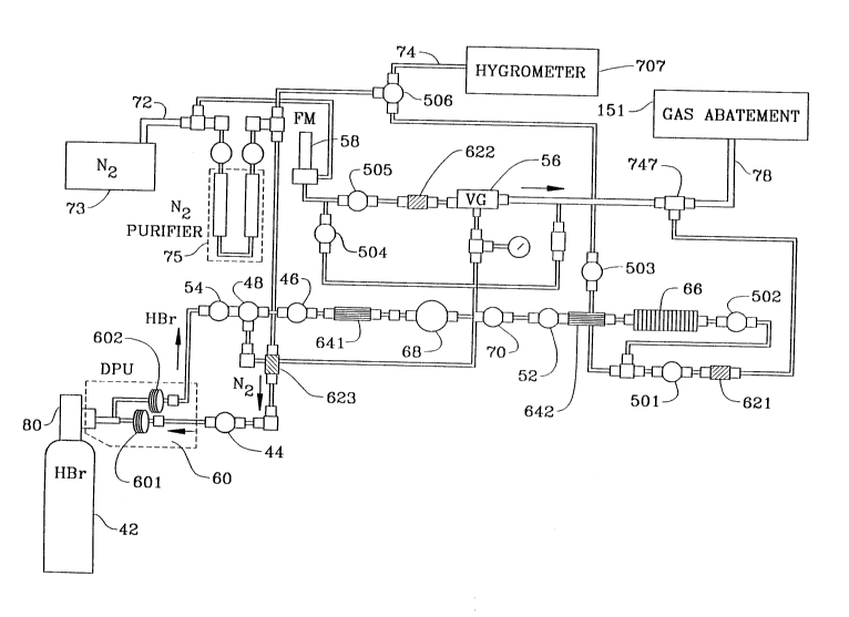
As illustrated in FIG. 2, a cylinder 42 of
corrosive HBr gas is connected to the gas distribution
system for purposes of providing a supply of HBr gas.
The cylinder 42 is designed to be replaceable so that
when the cylinder is emptied, another full cylinder can
be connected to the system. The gas distribution system
also includes several high pressure valves 44, 46, 48,
several low pressure valves 501, 502, 503, 504, 505,
506, a low pressure air control valve 52, pressure
sensors 54, 70 which measure the pressure of the
corrosive gas HBr before and after the pressure
regulator 68, a vacuum generator 56, a flow meter 58, a
deep purge or cross purge unit 60, several check valves
621, 622, 623, several filters 641, 642 and a mass flow
controller 66. A source of N2 73 is provided and is
connected with the distribution system by way of a house
line 72. The source 73 can be a liquid nitrogen storage
with an evaporator or an on-site N2 plant or N2 gas in a
cylinder, or any other N2 generator means. A N2 purifier
is also connected to the incoming N2 line 72 to deliver
`- ~170~0~
high purity or ultrahigh purity Nz as required by the
standards of the electronic industry. The various parts
of the gas distribution system described above are
interconnected with appropriate tubing (e.g., S~S 316L
EP tubings and SUS 316L BA tubings) having different
size diameters as illustrated in FIG. 2. The gas
distribution system also includes a pressure regulator
68 which can be of the general form illustrated in
FIG. 1 for reducing the pressure in the cylinder 42 to
the wor~ing pressure.
The various high or low pressure valves, whether
two port or three port valves, control the various gas
flow in two directions (on or off) while the check
valves allow the gas to flow only in one direction. The
deep purge unit DPU 60 comprises two pigtails 601, 602
which are connected to the valve 80 of the cylinder 42
and which assist in the gas purging procedure during the
HBr cylinder exchange. (The deep purge unit, DPU, can
be replaced by a cross purge unit.) The vacuum
generator 56 evacuates gas from the system to a gas
abatement device 151 through the line 78. The flow
meter 58 measures the nitrogen flow rate in the system.
The operation of the system shown in FIG. 2 involves
three basic steps, namely the initial dry down step, the
HBr flow step, and the cylinder exchange simulation.
Each of these steps is described below.
h 1 7 v ~ 0 6
--12--
1. The initial dry down
During the initial dry down, the cylinder valve 80
and valves 48, 501, 504, 505 and 506 remain closed. N2
gas flows through the purifier 75, valve 44, deep purge
unit (DPU) 60 and valve 46 to the system and the
moisture level of the purge N2 is measured by a
hygrometer 707 attached to the end of the line 74. When
the moisture content in the N2 reaches the required
value, the N2 flow stops. The purified N2 (about 20 ppb
H20) is necessary only for the initial dry down of the
complete line. For purging of the deep purge unit 60
and the cylinder valve 80 during the cylinder change, a
purified high grade N2 is sufficient. A purified low
grade N2 is used for other purposes like pneumatic valve
operation and dilution of corrosive gas before being
sent to the gas abatement device 151.
2. HBr flow
During the HBr flow, (or any other non-inert gas or
corrosive gas or reactive gas), the valves 44, 48, 503,
505 and 506 remain closed. The opening of the cylinder
valve 80 initiates gas flow from the cylinder 42 to the
system through the deep purge unit 60. The input
pressure (P) of the gas (cylinder pressure) is measured
by the pressure sensor (PS) 54. The pressure sensor 70
indicates the output pressure from the regulator 68.
The mass flow controller 66 controls the gas flow rate.
.
-
217~3~6
-13-
A gas with a constant pressure and flow rate flows to
the gas abatement device 151 through the line 78.
Nitrogen gas flows through the valve 504 and dilutes the
HBr gas in the connection 747 prior to entering the gas
abatement device 151.
3. Cylinde~ exch2nse simulation
This simulates the actual cylinder exchange in the
corrosive gas system. During the cylinder exchange
simulation, the cylinder valve 80 and valves 46, 502,
503, 504 and 506 remain closed. The opening of the
valve 505 activates the vacuum generator 56 and then,
opening of the valve 48 causes the removal of the HBr
gas, which remained in the deep purge unit 60, the
various cylinder valves, etc., the gas being sent to the
gas abatement device 151. Then the purge gas (N2) is
introduced into the line disposed between the valves 44
and 48 by closing the valve 48 and opening the valve 44.
Next, depressurizing the same part of the line is
obtained by closing the valve 44 and opening the valve
48. (This procedure, kno~n as cycle purge, is carried
out several times). Then, the cylinder valve 80 is
disconnected from the deep purge unit 60 and the opening
of the valve 44 creates a N2 flow from the pigtail bleed
601 to the atmosphere during the times the cylinder 42
is disconnected from the deep purge unit 60. After
about 2 minutes (the actual time needed to exchange a
r
~1~03~6
-14-
cylinder) the valve 80 of the cylinder 42 is reconnected
to the deep purge unit 60. Then, the atmospheric
intrusion into the cylinder valve is removed by the same
procedure that is used to remove the HBr at the
beginning. The HBr flow can thereafter start again.
With reference to FIG. 3, it has been found that in
a pressure regulator such as that illustrated in FIG. 1
which is in good operating condition (i.e., the pressure
regulator is free of internal and external leaks), the
output pressure PF is constant or substantially constant
with time so long as gas is flowing through the gas
distribution system. If the gas flow stops as a result
of, for example, the closing of a valve downstream of
the pressure regulator, the output pressure P~ of the
pressure regulator increases slightly in comparison to
that which is reached when gas is flowing and then once
again remains constant or substantially constant with
respect to time. However, if corrosion of the poppet 32
and/or the deposition of corrosion products on the
poppet 32 occurs, and/or if the spring force of the
poppet spring 34 weakens due to corrosion resulting from
the flow of the highly corrosive gases, the output
pressure of the regulator in the absence of gas flow
increases gradually due to the fact that the poppet
cannot tightly engage the seat 30 and completely close
the restrictor orifice 28. If the maximum pressure
21703~6
reached during a certain time period is represented by
PM~ then the condition of the regulator can be measured
by the following expression:
~P PM PF-
It has been discovered, therefore, that the
operating condition of the pressure regulator can ~e
assessed by continuously measuring the output pressure
of the pressure regulator when gas is flowing through
the system and in the absence of gas flow through the
system, and monitoring the pressure differential ~P that
exists between the output pressure of the pressure
regulator when gas is flowing through the system and the
output pressure of the pressure regulator in the absence
of gas flow.
lS To determine the specific parameters for assessing
the operating condition of the pressure regulator, tests
were performed to measure the pressure differential ~P
of the pressure regulator in connection with three gas
distribution systems, each designed in the manner
illustrated in FIG. 2. In addition to the components of
the gas distri~ution system described above, each system
was provided with a pressure sensor 70 positioned
immediately downstream of the pressure regulator 68 to
continuously measure the output pressure of the pressure
regulator 68. The three systems were operated so as to
simulate conditions which would likely result in three
21 ;7~306
-16-
different conditions of the pressure regulator -- a
properly operating pressure regulator, a malfunctioning
pressure regulator and a failed pressure regulator.
In each of the three test systems, an initial dry
down procedure was performed. That is, a He leak test
was initially carried out and all three systems were
then purged with purified N2 supplied from the house line
72. The usual range of flow rate for purging is between
about 0.5 to about lo standard liter per minute or SLM;
where 1 SLM = 0.167 x 10' m3/s. The first test system
was purged at 1 SLM with purified N, (<20 ppb H20) while
ba~ing at 70-80~C. In contrast, the second and third
systems were purged with purified N2 (<20 ppb H20) at
room temperature at the rate of 1 SLM. The moisture
level of the purging Nz was monitored by a hygrometer 707
allowing down to approximately 20 ppb H20 concentration
measurement (e.g., an electrolytic hygrometer like those
sold by MEEC0, Inc.) and connected to an output line 74
of each system. After several days (i.e., 1-2 days) of
purying, the moisture level of the Nz gas reached 100 ppb
at the end of the lines. The purging was then stopped
and a flow of pulsed HBr gas, controlled by the
pneumatic valve 52, was introduced into each of the
three test systems. During this pulsed HBr gas flow,
the output pressure of the pressure regulator 68 of each
test system was recorded constantly by the pressure
~170~06
transmitter 70 both in the presence of gas flow and in
the absence of gas flow. The gas flow rate was between
100 standard cubic centimeter per minute and 1000
standard cubic centimeter per minute.
As noted above, the process of exchanging a full
gas cylinder for an empty gas cylinder, if not properly
controlled, can be a major cause of the introduction of
corrosion in the gas line due to the intrusion of
moisture from the atmosphere. In order to simulate this
cylinder exchange in each of the three test systems, a
pigtail bleed of the deep purge unit 60 was disconnected
from the cylinder valve, exposed to the ambient air for
about two minutes and connected again to the cylinder
every day. After the simulated cylinder exchange
procedures were carried out for the three test systems,
each system was subjected to a purging procedure. The
purging procedure following the cylinder exchange for
the third test system was different from the purging
procedure used in connection with the first and second
test systems as described in more detail below.
In the case of the first test system, the part of
the system connecting the deep purge unit 60 to the high
pressure valves 44, 46, including the cylinder valve 80,
was purged cyclically with N, for five times in order to
2S remove atmospheric contaminants introduced during the
cylinder exchange. After this N2 purge, the same part of
- 217~3~
-18-
the system was cycle purged with HBr for five times in
order to further remove any contaminants. This
procedure was adopted to minimize the intrusion of
moisture to the system after the cylinder exchange and
thereby reduce the potential for corrosion within the
first test system.
In the case of the second test system, the purging
procedure after the simulated cylinder exchange was the
same as that used in connection with the first test
system. The only difference between the first and
second systems involved the initial dry down described
above in which the first system was dried down with
baking while the latter was not.
The N2 cycle purge after the simulated cylinder
exchange for the third test system was carried out in
the same manner as that for the first and second test
systems. However, the HBr purge after the N2 cycle purge
was not done. Therefore, the removal of contaminants
that were introduced into the system during the cylinder
change was not as efficient as in the case of the first
system or the second system and so the extent of
corrosion within the third system was significantly
higher than in the case of the first and second systems.
After the foregoing operations were carried out for
the three test systems (between twelve and twenty-four
times as shown in FIGS. 4A, 4B, 4C), the pressure
.
217~)3U6
--19--
regulator 68 for each system was Px~m;ned. The result
of that examination clearly identified differences in
the extent of corrosion due to the different initial dry
down and purging procedures associated with the three
systems. The pressure regulator from the first test
system exhibited no corrosion or deposition of corrosion
products on the poppet. Further, the poppet spring
remained substantial'y corrosion free.
As measured by the pressure sensor 70, the pressure
differential ~P of the regulator 68 for the first test
system fluctuated only very slightly, and remained smzll
and nearly constant with the number of cylinder change
simulations as illustrated in the graph of FIG. 4A.
Even after twenty-four cylinder exchange simulations,
the pressure regulator 68 exhibited no abnormality and
the pressure differential ~ was always less than about
0.5 kgf/c*.
The pressure differential oP of the pressure
regulator 68 for the second test system fluctuated
significantly, and gradually increased to about
0.9 kgf/cm2 with the number of cylinder exchange
simulations as illustrated in the graph of FIG, 4B.
After twenty-one cylinder exchange simulations, the
pressure differential ~P was less than 1.0 kgf/cm2.
Although the pressure regulator 6~ was still deemed
usable, the high value of the pressure differential ~P
2170306
-20-
(about 0.9 kgf/cm2) and the high fluctuations in the
pressure differential ~P indicated the onset of
malfunction. Upon P~m; nation, the pressure regulator
68 from the second test system was found to have minor
corrosion and minor deposition of corrosion products on
the poppet which would tend to inhibit the leak tight
closure of the restricted orifice 28 through engagement
of the poppet 32 on the seat 30 of the pressure
regulator. Also observed with respect to the pressure
.10 regulator 68 from the second test system was corrosion
on the poppet spring 34 which would tend to inhibit or
reduce the rebound ability of the poppet spring 34 in
-the absence of gas flow. This deposition of corrosion
products on the pappet 32 and corrosion on the poppet
spring 34 were deemed to be the causes of the observed
fluctuations in the pressure differential ~P with
respect to time as illustrated in the graph of FIG. 4B.
The pressure differential ~P of the pressure
regulator 68 from the third test system fluctuated
greatly and exceeded 1.0 kgf/cm2 after only eleven
cylinder change simulations as depicted in the graph of
FIG. 4C. Here, the pressure regulator 68 failed (~P >
1.0 kgf/cm~) much earlier than in the case of the
pressure regulator for the first system. Upon
~mi nation, it was observed that the pressure regulator
68 from the third test system exhibited a heavy
~17~3~6
deposition of corrosion products on the poppet 32 and
heavy corrosion of the poppet spring 34, both of which
inhibit the leak tight closure of the restricted orifice
28 through full engagement of the poppet 32 with the
seat 30 of the pressure regulator. This heavy
deposition of corrosion products on the poppet 32 and
the heavy corrosion of the poppet spring 34 were deemed
to be the cause of the failure of the pressure regulator
of the third test system through internal leak.
Based on the foregoing, it was discovered that the
variation in pressure differential ~P with respect to
time depends quite strongly on the purging procedure
associated with the cylinder exchange (i.e., with the
corrosion level in the system, particularly the pressure
regulator). For a corrosion free line, it was found
that the pressure differential ~P is quite small, on the
order of less than 0.5 kgf/cm', and does not fluctuate
with time. For a failed pressure regulator due to
corrosion and/or deposition of corrosion products on the
poppet 32, and/or due to the corrosion of the poppet
spring 34, the pressure differential ~P is quite large,
on the order of greater than 1.0 kgf/cm2, and gradually
increases with time. Thus, the pressure differential ~P
can be regarded as an arbitrary unit for the indication
of the operating condition of the pressure regulator in
the following manner.
. ~ ~
3 ~ C
-22-
When oP < O.5 kgf/cm' and does not fluctuate
with time, the regulator is functioning
normally.
When 0.5 kgf/cm- < ~P < 1 kgf/cm' and
fluctuates greatly with time, the regulator is
not functioning normally, indicating the onset
of a malfunction.
When ~P > 1 kgf/cm- and increases gradually,
the regulator has failed due to an internal
leak.
When the output pressure in the absence of gas
flow decreases gradually, even very slightly,
it indicates a leak to outside, i.e., an
external leak.
Thus, in accordance with the present invention, the
operating condition of a pressure regulator in a
- corrosive gas distribution system with respect to the
presence or absence of internal or external leaks can be
assessed by (continuously) monitoring or measuring the
output pressure of the pressure regulator in the
presence and absence of gas flow through the system.
Khowing the output pressure of the pressure regulator
when gas is flowing through the system and comparing
that pressure to the output pressure of the regulator in
the absence of gas flow to determine the magnitude of
the pressure differential allows the operating condition
0 6
of the regulator to be readily determined. This
advantageously allows pressure regulator malfunctions to
be detected at an early stage so that corrective action
can be taken before the occurrence of a corrosive gas
leakage. Thus, the safety as well as the productivity
of the gas distribution system can be increased to a
significant extent.
This technique can be used manually as well as in
computerized gas distribution systems to predict
malfunctions automatically and correct them prior to the
occurrence of a potentially harmful accident. In the
case of computerized gas distribution systems, the
pressure differential P and its variation with time can
be automatically measured with the results being
automatically fed to safety equipment so as to achieve
safe and trouble free operation of the total corrosive
gas distribution system.
In the case of a computerized cylinder cabinet, for
example, the system according to the invention can be
implemented as follows:
The gas distribution system in the cylinder cabinet
provides gas with constant pressure (P) and the computer
continuously monitors this pressure P (output pressure).
The gas flow rate is controlled by the device, e.g., a
reactor, connected to the gas distribution system in the
cylinder cabinet.
~7~3~
-24-
Since the process according to the invention uses
data on output pressure P both in the presence and
absence of the gas flow, information on the gas flow is
also sent to the computer in order to determine to which
category (with or without gas flow) the measure done on
the pressure P belongs. To make this information
available to the computer of the gas cabinet, a gas flow
meter may be installed at the outlet of the gas
distribution system in the cylinder cabinet.
It is also possible, without installing a flow
meter, to have, e.g., a signal sent by the device te.g.,
the reactor) to the computer to indicate to the computer
if the gas flows or not.
Having this information, the computer of the gas
cabinet can continuously or from time to time calculate
the ~P between P~ and the greater of P~ and PM as
previously defined, in order to determine if the
pressure regulator, or any other device tested the same
way as explained hereabove, is functioning normally, is
not functioning normally or has already failed. The
computer can generate a print-out or any other light or
sound signal as soon as the tested device (e.g.,
pressure regulator) has been determined to be
malfunctioning. It is also well within the skiils of
one of ordinary skill in the art to provide a special
alarm signal (sound, light, special print-out,
~17f~3~
-25-
separately or all together) in case of failure
detection.
The principles, preferred embodiments and modes of
operation of the present invention have been described
in the foregoing specification. However, the invention
which is intended to be protected is not to be construed
as limited to the particular embodiments disclosed.
Further, the embodiments described herein are to be
regarded as illustrative rather than restrictive.
Variations and changes may be made by others, and
equivalents employed, without departing from the spirit
of the present invention. Accordingly, it is expressly
intended that all such variations, changes and
equivalents which fall within the spirit and scope of
the present invention as defined in the claims be
embraced thereby.