Note: Descriptions are shown in the official language in which they were submitted.
S
..~, __;:~~~ 217 fl 3 ~ 2
t~.~, ~ . _~ r.- y
.~ TRA,~~ ~.6~i ~~i~
Sommer PCT/~P X4/028?? - pC ~4 454 ~
A Device for Peeling ~Iongated Vegetables
The invention relates to a device for peeling asparagus and
similar elongated vegetables, including a passage for passing
the vegetable through and arranged in the region of the
passage at least one peeling blade which acts upon the
periphery of the vegetable and presses flexibly against the
vegetable, wherein the cutting edge {19) of the peeling blade
is preceded in the peeling direction {23) by at least one
feeler (~Q, 20') which lies against the periphery of the
vegetable to be peeled and is connected substantially rigidly
to the peeling blade, wherein each peeling blade is held on,
and is capable of swivelling relative to, a blade arm mounted
so as to be capable of swinging out crosswise to the
longitudinal direction of the passage against a restoring
force and each peeling blade has a cross section in the shape
of a circle segment.
Manually peeling asparagus, for example, is laborious and
time-consuming, because every single stick has to be peeled
in several stages, each stage removing only a strip of the
outside skin of the asparagus. After one strip has been
removed, the asparagus has to be turned through a certain
angle about its longitudinal axis relative to the peeler, so
that the next strip can be peeled. If the angle selected is
too large, an unpeeled area is left between the two strips.
That strip then has to be peeled off separately in an extra
step. Since, however, the peeled portion of the outer skin of
the asparagus is difficult to distinguish from the unpeeled
portion, the person peeling the asparagus may fail to notice
that it has been turned through too large an angle and
therefore not all the skin is removed. There is this risk
particularly if relatively large quantities of asparagus are
to be peeled and after some time the person doing so becomes
inattentive or careless due to the work being monotonous and
offering little in the way of relief.
It is also difficult for persons ~.nexperienced in peeling to
keep the depth of cut constant. In this case islands of
unremoved skin may be formed between the individual peeled
strips. To avoid this, the tendency is usually to select a
greater depth of cut and/or a smaller angle of turn,
resulting in the removal of an unnecessarily large amount of
material.
The uneven depth of cut can be largely precluded by using
.5 already known implements having a swivel-mounted blade with a
cutting edge arranged in a slit. ~Iowever these implements
represent only a minor improvement, because the asparagus
still has to be peeled in a tedious working process involving
several stages.
~0
Since the relatively thin asparagus is difficult to grasp
during peeling and since the sharp blade has to be moved very
closely past the hand holding the asparagus, there is
considerable risk of injury when peeling asparagus manually.
Therefore a peeling device of the kind mentioned at the
outset has been provided which has a passage through which
the vegetable to be peeled oan be passed by m~a~s of a
feeding device tcf. DE-U-78 16 311). Several peeling blades
34 are provided in the region of the passage, these being
arranged in pairs on mutually opposed sides of the passage
and acting upon the periphery of the vegetable. The peeling
blades of the known device are held on and are capable of
swivelling relative to the blade arm. The blade arms for
their part are mounted so as to be capable of swinging out
- - 21 ~~~~2
crosswise to the longitudinal direction of the passage
against a restoring force. During the peeling operation, the
peeling blades of circle segment shape in cross section
flexibly press against the vegetable to be peeled. As this
vegetable is advanced, the straight cutting edges of the
blades pare the outer skin or layer in strips.
Hy means of the blade arms mounted so as to be capable of
swinging out against a restoring force and by means of the
~0 peeling blades capable of swivelling relative to the blade
arms, the known device enables such vegetables to he peeled
as are non-uniform in cross section over their length.
However, even when cutting into the vegetable such swivel-
mounted peeling blades are liable not to fully encompass the
35 skin and then not to peel the skin completely in a
satisfactory way.
DE-A-I7 57 433 has disclosed a peeling device with peeling
blades held rigidly in the blade arms displaceable crosswise
20 to the longitudinal direction of the passage. As the peeling
blades are fastened rigidly, they are less able to adapt to
any crass-sectional anomalies of the vegetable to be peeled.
~'or this reason it is necessary with this known device that,
for instance, the eyes in the asparagus skin first be shaved
25 off before the peeling blades come into engagement. This
requires an additional working step and may also have an
effect on the peeling result.
Therefore the object underlying the invention is particularly
30 to provide a device of the kind mentioned at the outset,
permitting asparagus and similar elongated vegetables to be
peeled quickly and simply even on a relatively large scale,
practically without risk of injury, even in manual operation
of the device. The vegetable is to be peeled with as little
21 ~03~ ~
waste as possible and with a minimum of skin left on the
vegetable.
This object is accomplished according to the invention in the
device of the kind mentioned at the outset particularly in
that the peeling blade or peeling blades have a concave
cutting edge.
Since the peeling blades are swivel-supported an the blade
f;7 arms mounted so as to be capable of swinging out crosswise to
the longitudinal direction of the passage, they can adapt
well to the unevennesses of a vegetable. As the peeling
blades are shaped according to the outer contour of the
vegetable and have a circular arc-shaped cross section, the
vegetable can be peeled round the whole of its peripheral
area with only a few peeling blades. ~n especial advantage of
the device embodying the invention is that the peeling blades
have a concave cutting edge pointing or oriented with its
circular arc shape radially in the direction of insertion.
20 Thus when cutting into the vegetable, the peeling blades can
penetrate better into its skin by virtue of their concave
cutting edge.
Since the device embodying the invention can be stood or can
2~ be held outside the area of the passage, far away from the
peeling blades, the peeling operation involves virtually no
risk of injury. The device in keeping with the invention
reduces the peeling operation to only one activity, namely
pushing the vegetable through, enabling vegetables to be
30 peeled even on a relatively large scale within the shortest
amount of time.
Since vegetables are generally not constant in diameter over
their length, at least one of the blades is movable in the
2~ ~03~~
crosswise direction of the passage and is flexibly deflected
towards the vegetable by force of pressure.
In a preferred embodiment of the invention, the swivel axis
of the blade arms is spaced upstream of the cutting edge.
Here and in the following description, the terms upstream and
downstream will he used to denote positions in relation to
the direction in which the vegetable is inserted in or pushed
through the passage. Through this lever action of the blade
~0 arm, the blade can be moved relatively far in the crosswise
direction of the gassage, without any substantial change to
the contact pressure of the blade against the vegetable. ~y
this means vegetables inserted off-centre or slantwise with:
respect to the longitudinal central axis of the passage are
1~ also peeled largely correctly. Zn addition, the lever enables
the required small contact pressure of the blades against the
vegetable to be realized in a simple fashion.
The peeling device is especially compact in design if the
20 device has a plurality of peeling blades of which at least
two paired peeling blades are arranged on opposite sides of
the periphery of the passage. If several, such peeling blades
or pairs thereof are arranged in different levels
perpendicular to the direction of passage, the vegetable can
25 be peeled in one operation round the whole of its peripheral
area. In order that the peeling blades cannot injure the
user, it is suitable if the housing reaches over all the
blade levels and outwardly covers the peeling blades
throughout the periphery of the passage.
In an advantageous embodiment, the peeling blades or pairs
thereof are evenly spaced over the periphery of the passage.
Since the device embodying the invention has several peeling
blades in the region of the passage which treat different
peripheral portions of the vegetable, a vegetable can be
21 ~~3~2
simply pushed, even manually, through the passage and at the
same time he peeled over at least a large portion of its
periphery. If the peeling blades are evenly distributed over
the periphery of the passage, the vegetable peeled by the
device displays a uniform, largely symmetrical cut.
In order to be able to peel a vegetable in only one pass or
peeling operation, a preferred embodiment of the invention
proposes that the device has preferably three axially spaced
pairs of peeling blades evenly distributed over the periphery
of the passage. In this emhodiment pith three pairs of
peeling blades, most sorts of vegetable can be fully peeled
over their entire periphery and length, even if the vegetable
in question is pushed only once through the passage, past the
15 peeling blades. ,Test for radish it may be advisable to
provide two pairs of peeling blades in the region of the
passage, whereby the radish to be peeled then has to be
pushed through the passage of the device, turned, and pushed
through again.
In order that the blade arms are pressed against the
vegetable to be peeled separately from one another and can
adjust themselves optimally to unevennesses of the vegetable,
it is suitable if at least one restoring spring is assigned
to each blade arm as a restoring element and if these
restoring springs preferably take the form of leg springs.
An advantageous embodiment of the invention proposes that the
restoring springs are preferably detachably held in a housing
and act upon the associated blade arm particularly on the
side facing away from the passage. As the restoring springs
are detachably fastened in the housing, it is easier for the
device embodying the invention to be put together and taken
apart when, for example, it is to be thoroughly cleaned ar
3~ repaired.
_ ~17030~
Instead of such restoring springs, however, it may also be
suitable for the blade arms to be capable of swinging out
against the restoring force of at least one rubber ring.
J
In one emhadiment of the invention, the rubber ring is
arranged on the exterior of the housing and the pressure
force of the rubber is transferred to the blade arm with the
aid of a transfer pin movable radially with respect to the
~0 passage. The rubber and the transfer pins are then accessible
from the outside of the housing and can be easily removed for
cleaning purposes, without the cleaner coming into contact
with the sharp blades.
However, the rubber ring may also be arranged inside the
housing. In that event, the rubber ring is preferably
arranged in such a way as to span, and bear against the
outside of, a plurality of blade arms distributed as evenly
as possible over the periphery of the passage. The rubber
20 ring is then held by the blade arms in spaced relationship to
the passage and cannot come into contact with the stick of
asparagus.
This arrangement of the rubber ring is advantageous
2~ particularly if and when the housing has an insert carrying
the blade arms. The insert is then easy to place in the
housing together with the blade arms held together by the
rubber ring. Given such a rubber ring acting an the blade
arms inside the housing, it is possible to dispense with any
30 further externally arranged rubber rings and transfer pins,
at least for the peeling blades having a comparatively short
blade arm.
If there are several levels of blades, it is advantageous to
3~ arrange some of the rubber rings inside the housing and the
2~~03~2
others on the exterior of the housing. In this case the
rubber rings for the upper levels of blades are suitably
arranged internally, whereas the rubber rings for the lower
levels of blades are arranged on the exterior of the housing
in order that they cannot get into the region of the passage.
r~ further development of the present invention proposes that
the preferably substantially cylindrical or annular housing
has on its outer periphery at least one contact point for
attaching a pedestal and/or a further housing. Such a
development of the housing enables it to be connected in a
practically modular fashion to further devices and/or at
least one pedestal. In case of such combination, it is
suitable if these devices have different peeling blades
and/or passages differing in diameter for peeling different
vegetables or sorts of vegetables.
One embodiment which is especially simple and easy to handle
proposes that each housing has several, preferably three,
2~ equi-circumferential contact points and i.s adapted to be
detachably connected to at least one further housing and/or
to a pedestal by means of a form-fit joint, particularly by
means of a slot and key joint. Such a form-fit joint between
the individual housings enables the respedive devices to be
~5 simply joined and separated. When joining several devices,
two of the three contact points of the outer housing may for
instance be used for connection to adjacent devices, whereas
the third canta.ct point is used for a pedestal. Thus a
peeling device composed of several housings can be stabiy
30 stood.
It is especially advantageous if the blade arms each have a
forked holder engaging the associated peeling blade arid if
the two fork ends engaging the peeling blade are preferably
JJ elastically expandable for blade removal. By expanding the
21 ~039~
fork ends engaging the peeling blade, the peeling blade can
be removed from the forked holder and if necessary be
replaced by a new peeling blade. since the preferably elastic
fork ends of the holders only have to be expanded for
changing the peeling blades, no additional tool is required
for blade detachment.
It is especially suitahle if the blade arms are made of
plastic. such blade arms made of plastic are not only
.0 inexpensive to make, but they do not rust and can also be
easily expanded in the region of their elastic, forked
holders for removing the peeling blades.
It is advantageous if the peeling blades have journals at
1~ either end, engaging with bearing recesses or similar bearing
openings of the associated forked holder. This swivel
mounting of the peeling blades facilitates their smooth
swinging movement and permits their simple detachment from
the forked holders of the blade arms.
To limit the swinging movement of the peeling blades in their
swivel bearings, a preferred embodiment of the invention
proposes that the journals and forked holders have oblique
sides in spaced relationship to each other and to the contact
surface between the journals and the associated bearing
openings. These sides compose co-operating stops and counter
stops to limit the tipping and swinging movements of the
peeling blades.
The smooth swinging movement of the peeling blades and their
good rotary guidance is enhanced if the journals of the
peeling blades and the sides of the forked holders defining a
bearing opening are rounded in the region of their common
contact surface.
J
~~70~~
t~
A further development of the invention consists in that the
peeling blades are in each case connected substantially
rigidly to at least one additional feeler. As considered in
the direction of insertion, the additianal feeler is arranged
spaced from the cutting edge of the associated peeling blade
to swivel the latter from a non-operative position into a
cutting position. The device, serving particularly for
peeling asparagus, is in this case designed in such a way
that when the asparagus has not yet contacted the additional
~0 feelers, the peeling blades are swung out in a non-operative
position in which the cutting edges are swivelled outwards.
The peeling blades are swung into their cutting position only
when the asparagus tip has reached the additional feelers
spaced downstream of the cutting edge of the peeling blade.
~5 Therefore not the delicate asparagus tip, but only the stick
behind it is peeled, as is customary.
In an embodiment of especially simple design, contemplated
particularly far peeling asparagus, the swing back of the
~0 peeling blades from their cutting position into a non
operative position is accomplished by the centre of gravity
of the peeling blades being above the swivel axis of the
blades. In this ease the device is preferably arranged in
such a way that the direction of insertion is substantially
25 in the direction of gravity.
In an advantageous embodiment of the invention there are
restoring springs or the like swinging the cutting edge
outwards in the non-operative state of the blades. Such an
30 embodiment can then be used in any operating positions.
If the asparagus is pushed tip first into the passage, the
asparagus tip moves past the outwardly deflected cutting
edges, without contacting them. As soon as the tip touches
35 the additional feelers, the peeling blades are pressed
2~ ~o~~~
11
against the vegetable. The blades associated to the
additional feelers hence swing from the non-operative
position into the cutting position and the cutting operation
begins. Py means of the additional feelers it is hence
achieved that the peeling operation begins only after the
asparagus tip, hence at its neck, and the delicate tip is not
damaged by the blades.
If the device embodying the invention is to be used far
peeling carrots, cucumbers or similar elongated vegetables,
it is suitable if the peeling blades in each case have a peel
deflector arranged downstream of their cutting edge. That
free, end portion of the deflector which is remote from the
cutting edge is preferably angled or bent outwards. The
~5 opposite portion of the deflector bears in particular against
the outside of the cutting blade and/or joins the cutting
blade. The vegetable peel sliding along the outer surface of
the peeling blade downstream of the cutting edge is deflected
outwards by the peel deflector. Therefore it can no longer
~0 come within reach of and interfere with downstream peeling
blades.
ff the vegetables are to be fully peeled throughout their
length, it is suitable if the centre of gravity of the
2~ peeling blades is below the swivel axis of the blades. This
arrangement of the centre of gravity of the peeling blades
practically ensures that the peeling blades are in their
cutting position even when in their non-operative state.
30 A preferred embodiment of the invention proposes that as
considered in the direction of insertion, the front, free end
area of the feelers is in each case preferably angled
outwards in a funnel shape counter to the direction of
insertion. Particularly if at least one restoring Spring is
3~ assigned to each blade arm as restoring element, this funnel-
CA 02170392 2005-02-04
30898-1
12
shaped configuration of the feelers arranged upstream of the
cutting edges means that a wide variety of vegetables with a
wide range of diameters are encompassed by the peeling
blades and peeled in the device embodying the invention.
Further features of the invention follow from the
description given below of exemplary embodiments of the
invention, taken in conjunction with the claims and
drawings. The individual features may be realized singly or
severally in an embodiment of the invention.
In accordance with this invention, there is
provided a device for peeling elongated vegetables
comprising: a housing having a passage defined
therethrough, the passage extending in a longitudinal
direction of the housing and having a first end adapted for
insertion of a vegetable into the passage, which defines a
direction of vegetable insertion, and a second end adapted
for removal of the vegetable from the passage; a peeling
blade located in the housing in proximity to the passage,
the peeling blade having a cutting edge adapted to act on a
periphery of a vegetable and being movably mounted for
movement crosswise to the longitudinal direction to press
against the vegetable; and a feeler connected to the peeling
blade, the feeler being located upstream of the blade in the
direction of vegetable insertion and being adapted to lie
against a periphery of the vegetable.
A peeling device and parts thereof are depicted in
the drawings on different scales and partly in schematized
form, in which
Fig. 1 is a partly sectional side view of a
peeling device, showing the two upper blades of the pairs
thereof distributed over altogether three levels,
CA 02170392 2005-02-04
30889-1
12a
Fig. 2 is a fragmentary, partly sectional view of
the peeling device of Fig. 1 in the region of the passage,
depicting a blade arm in different swivel positions,
Fig. 3 is a front view of a peeling blade of the
peeling device of Fig. 1, showing part of the blade arm,
Fig. 4 is a side view of a peeling blade of Fig. 3,
showing part of the blade arm,
Fig. 5 is a fragmentary, partly sectional view of
the peeling device of Figs. 1 to 4 in the region of the
passage, as the peeling operation commences,
~1~03~?
Fig. 6 is a fragmentary, partly sectional side view of a
peeling device similar to that of Figs. 1 to 4,
wherein a restoring spring as restoring element is
assigned to each of the blade arms of the peeling
device and holds the associated arm in the region of
the passage of the peeling device,
Fig. 7 is a plan view of the peeling device of Fig. 6,
Fig. ~ is the peeling device in a sectional side view turned
through y0° compared to that in Fig. 6,
Fig. 3 is a blade arm in the region of the swivel bearing of
its peeling blade,
Fig. 10 is a front view of a peeling blade far the peeling
device of Fig.6, whdreby the peeling blade has an
additional feeler arranged downstream of the cutting
edge and is provided particularly for peeling
asparagus,
Fig. 11 is a plan view of the peeling blade of Fig. iQ,
Fig. 12 is a side view of the peeling blade of Figs. 10 and
11,
Fig. 13 is a side sectional view of the peeling blade of
Figs. 10 to 12,
Fig. 14 is a front view of a peeling blade, whereby a peel
deflector is arranged downstream of the cutting edge
of the peeling blade,
Fig. 15 is a plan view of the peeling blade of Fig. 14,
3~
2~ 7032
~'ig. 16 is a side view of the peeling blade of figs. 14 and
25 and
rig. 27 is a side sectional view of the peeling blade of
Figs. 14 to 16.
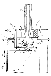
Fig. 1 shows a partly sectional view of a peeling device 1
having a substantially cylindrical housing 2. The housing 2
has an insert 3 with a passage 4 extending generally
t~ concentrically with respect to the longitudinal central axis
of the housing 2. The passage 4 is of substantially
cylindrical shape in its middle and lower area, flaring in a
funnel shape in its upper area. The insert 3 has altogether
six external grooves 5 evenly distributed over the periphery
i6 of the passage 4. The grooves 5 extend in the longitudinal
direction 6 of the passage 4 and in cross section are
arranged radially with respect to its longitudinal central
axis. In each of the six grooves 5 there is one swivel
bearing ~ for a blade arm 9 extending into the respedive
~fl groove 5 and projecting into the interior of the housing 2.
The swivel bearing 0 is located in the raglan of the top 7 of
the insert, approximately in the centre of the groove 5. The
free end of the blade arm 9 carries a forked holder 20 of
generally semicircular shape. The forked holder 10 is
26 centrally and rigidly connected to the blade arm 9 at an
angle of 90° and has a swivel bearing 11 at either end for
swivel mountings a blade 2~. A transfer element 23, which is
movable radially with respect to the passage 4, engages the
blade arm 9 approximately midway. The transfer element 23
0 consists of a press pin 14 surrounded in part by a sheath 15
to reduce the external friction. On the exterior of the
housing 2, the press pin 14 has a groove running in the
circumferential direction of the housing 2. Inserted in the
groove is a rubber ring 16 which extends round the periphery
35 the housing 2 and subjects the press pin 24 to pressure
2.~ 703.9
directed towards the blade arm ~. The blade holder 17 and the
blade 12 are thereby deflected in the direction of the
longitudinal central axis i8 of the passage 4, according to
F ig. 2.
The rubher ring I5 also acts upon a second transfer element
(not shown) arranged on the periphery of the insert 3 so as
to be rotationally staggered through 180° with respect to the
first transfer element. The second transfer element acts upon
0 a blade arm g' which extends into the groove 5' opposite
groove 5 and on a holder 10' carries a further blade 12'
which in relation to blade 12 is rotationally staggered
through 180° with respect to the longitudinal central axis 18
of the passage 4. The peeling device 1 thus has a pair of
~5 blades 22, 22' arranged in a plane perpendicular to the
longitudinal central axis 18.
beneath the latter level of blades are two further ones each
about 10 mm apart. Each level has a pair of blades which, in
20 relation to the level above, is rotationally staggered
through 120° with respect to the longitudinal central axis IS
of the passage 4. Hence there are altogether six blades
evenly distributed over the periphery of the passage 4. The
individual levels of blades each have a separate rubber ring
2~ I6, so that the blades 12, I2' can be deflected largely
independently of one another, without causing any substantial
change in the contact pressure of the other blades.
The insert 3 can be removed from the housing together with
30 the blades I2, I2' and blade holders I7, I7', allowing the
inside of the peeling device 1 to be simply cleaned.
Figure 8 illustrates a front view of the blade I2, showing
the two swivel bearings 11 which are arranged approximately
2~'~~3~2
level with the cutting edge iy and engage with the holding
element i0.
The blade i2 is cylindrically bent in the d~.rection of the
SW7.Ve1 axis 22, the radius of bend corresponding
approximately to the radius of a very large stick of
asparagus 50. By this means, thin as wail as thick sticks 50
can be treated by the device 2, without having to change the
blades 12, 12' in number or arrangement. Oonditioned by the
~o cylindrical bend of the blade 12, only the central area of
the cutting edge i~ lies against the periphery of a thin
stick 50, peeling only a comparatively narrow strip of the
outer skin. In the case of thick sticks 50, the cutting edge
i9 contacts a substantially wider strip of outer skin 53,
i~ 53', so that the stick of asparagus 50 is also peeled round
the whole of its peripheral area.
The cutting edge i9 is also bent in the shape of a circle
segment in the longitudinal direction 6 of the passage 4,
20 improving the cutting action of the blade 12 particularly
when cutting into the asparagus.
On the side situated in the cutting direction 23, the blade
I2 furthermore has a feeler 20 rigidly connected to the
25 cutting edge I9. On the side of the blade 12 facing away from
the feeler 20 is an additional feeler 21 likewise rigidly
connected to the cutting edge 19. fig. 4 represents a side
view of the blade I2, showing feeler 20 and additional feeler
21.
The functions of feeler 20 and additional feeler 21 will be
explained below with reference to digs. 1 and 5. Before the
asparagus 50 is inserted in the passage 4, the blades 12, 12'
are in their non-operative position in which the feelers 20,
20' are deflected by gravity towards the blade arms 9, 9'.
2~7~~~~
.7
The asparagus 50 is now inserted lengthwise, tip 51 first, in
the passage 4. In so doing, the asparagus tip 51 contacts the
additional feelers 21, 21' and deflects them outwards (fig.
1 ) . As a result, the feelers 20, 20 ' swivel inwards and lie
against the outer surface of the asparagus at about the level
of the asparagus neck 52 (Fig. 5). At the same time the
cutting edges 19, 19' contact the asparagus 50 and the
cutting operation begins. The additional feelers 21, 21'
hence cause the peeling operation to begin only after the
~0 asparagus tip 51, at about the level of the asparagus neck
52. For this purpose the distance between the swivel bdarings
11, 11' and the lower edge of the additional feeler 21, 21'
is adapted to about the length of the asparagus tip 51.
During the cutting operation the feeler 20, 20' slides along
i5 the outer surface of the asparagus 50 and prevents the
cutting edge 19, 19' from swivelling too far into the
asparagus. The cutting direction of the blades 12, 12'
thereby extends tangentially to the outside of the asparagus
50, achieving a uniform depth of cut.
2~
To facilitate inserting the sticks of asparagus 50 in the
passage 4 and removing them at the opposite end of the
peeling device 1, the housing 2 of the peeling device 1 is
suitably fastened to a holding arm in such a way that the top
25 side and bottom side of the peeling device 1 are freely
accessible. ~y way of example, the holding arm may have a
pedestal for standing the device or it may be clamped to
tabletop, for instance, by a clamping device.
30 Fig. 6 illustrates the preferred embodiment of a peeling
device 1' largely conforming with the peeling device 1 of
Figs. 1 to 5. The device 1' also has a passage 4 for passing
through the vegetable to be peeled. A plurality of peeling
blades 12 acting upon the peripheral area of the vegetable
35 are provided in the region of the passage 4 of the peeling
21'0302
device 1'. One blade arm ~ is associated to each peeling
blade 12 and has a forked holder 20 for the respective
peeling blade 12.
The blade arms ~ are in each case mounted so as to be capable
of swinging out against the restoring force of a restoring
spring 24 in the housing 2 of the peeling device 1'. The
restoring springs 24 each associated to a blade arm are here
in the farm of leg springs. The leg springs have their free
s~ spring wire ends detachably held in insert openings of the
housing 2 and act upon the associated blade arm ~3 on the side
facing away from the passage 4.
As becomes apparent from ~'ig. 6, the blade arms 9 with their
swivel axes 2~ are in each case rotatable in a bearing recess
of an inner housing ring 2~. The blade arms are secured in
these bearing recesses by a central noosing ring 27 which is
slipped onto a portion of the inner housing ring and held in
position there by fasteners 28. The central housing ring 27
2C~ rests on the inner annular flange 29 of an outer housing ring
30 and can be removed upwardly from there counter to the
direction of insertion.
The swivel axes 25 of the blade arms g are spaced upstream of
25 the peeling blades 12.
Of the six peeling blades 12 and appertaining blade arms 9 of
the peeling devioe 1', two paired peeling blades 12 at a time
are arranged on opposite sides of the periphery of the
30 passage 4. These pairs of peeling blades are arranged in
staggered relationship to one another in the longitudinal
direction of the passage 4.
The peeling blades I2 have journals 31 at either side, each
3~ engaging with a bearing opening 32 in the associated forked
2.~ ~D3~~
19
holder i0. ,~aurnais ~1 and forked holders 10 have oblique
sides 34 and 35 in spaced relationship to each ether and to
the contact surface 33 between the journals 31 and the
associated bearing openings .~2. These sides 34 and ~5 compose
~i co-operating stops and counter stops to limit the tipping and
swivel movements of the peeling blades 22. 3ournais 31 and
bearing openings ~2 in each case compose a swivel bearing 21.
The peeling blades I2 rotatabie in these swivel bearings 11
can adapt wail to the outside surface of a vegetable as it is
pushed through. To enable the peeling blades i2 to be evenly
guided and rotated during these swivel movements, the
journals .i1 of the peeling blades 12 and the sides ~5 of the
forked holders 10 defining a bearing opening ~2 are rounded
in the region of their common contact surface 3.~, as is clear
particularly from the detail of dig. 9.
The blade arms 9 are here made of plastic. As a result of
this and as a result of the dimensioning and configuration of
the forked hailers 20, the two fork ends applied to a peeling
blade 12 are elastically expandable for blade removable,
without requiring much effort ar a special tool.
These peeling blades 12 can therefore be simply detached and
replaced by new or different peeling blades 12.
It may also be advisable to change the peeling blades if, for
example, the thickness of peel is to be altered. The fixed
distance between the cutting edge 29 on the one hand and the
opposite free end area 20a of the feeler 20 on the other hand
determines the thickness of peel. The thickness of peel can
be selectively varied by simply replacing the blades 12, 12a
and/or 12b by blades having a different radial distance
between the blade portions 19, 20a.
~~ 70~~
As shown by Figures 10 to 13 on the one hand and r figures 14
to 17 on the other hand, two different blade types are
provided for the peeling device 1'.
similarly as in Figures 1 to 5, the peeling blade 12a shown
in figures ltd to 13 serves particularly for peeling
asparagus. It has an additional feeler 21 arranged downstream
of the cutting edge i9. since the centre of gravity of the
peeling blade 12a in rigures 10 to 1:~ is above the swivel
~t~ axis il of the blade, the peeling blade can swivel by itself
into its non-operative position in which the feeler 20 points
outwards and the additional feeler 21 points to the passage
4.
i5 As a stick of asparagus is pushed through the passage 4 of
the peeling device 1', the peeling blade 12a is moved into
its cutting pasition when the delicate asparagus tip touches
the additional feeler 21. since the asparagus tip has then
already passed the cutting edge 19, not the tip but only the
2c~ stick of asparagus is peeled, as is customary.
In contradistinction the peeling blade 12b illustrated in
Figures 14 to 17 is provided for vegetables which are to be
peeled throughout their length. Instead of having an
additional feeler 21, the peeling blade 12b of Figures 14 to
17 has a peel deflector 36 arranged downstream of the cutting
edge 19.
Whereas the portion of the peel deflector 36 facing the
cutting blade 12b bears against the outside of the cutting
blade, the opposite, free end portion 37 thereof is angled
outwards. The vegetable peel removed by the cutting edge 19
therefore slides over the peel deflector ~6 outwards where it
can no longer come within reach of and interfere with
3~ neighbouring, downstream peeling blades 12b.
~i 70~0~
Since the centre of gravity of the peeling blade 12b is
beneath the swivel axis 11, the peeling blades i2b when idle
are also held in the cutting position illustrated in Figures
16 and 17. In comparing Figures 10 to 13 and Figures I4 to l7
it becomes clear that the journal 3i of cutting blade 12b is
arranged in the region of the feeler 20 and the journal 31 of
cutting blade i2a is spaced downstream of the cutting edge
29.
i0
The cutting blades ~.2a and 12b of convex curvature in cross
section are circular arc-shaped at the mutually adjacent
sides of cutting edge 2g and feeler 20. Since, compared to
the feelers 20, the circular arc shape of the cutting edge 19
15 has a larger radius in the longitudinal direction and a
smaller radius in cross section, the distance between the
mutually adjacent sides of cutting blades I2, I2b and feelers
20 increases outwardly from about either side of their
longitudinal central axis ~S. In their outer edge area the
20 mutually adjacent sides of cutting blades 12a, 12b and
associated feelers 20 extend spaced from and parallel to the
respective swivel axis. ~y virtue of this Configuration of
the peeling blades 12a, I2b, the vegetable skin is easily
intercepted and guided well during the peeling operation,
2~ without being able to lodge at the outer edge areas between
peeling blades and feelers 20.
Figures 1~ and l7 clearly show that the free end area 20b of
the feelers 20 is preferably angled outwards in a funnel
30 shape counter to the direction of insertion. This funnel-
shaped configuration of the feelers 20 ensures that even when
vegetables differing greatly in diameter are pushed into the
passage of the device 1', they are sure to be intercepted by
the peeling blades. This automatic adjustment of the device
1' to the differing diameter possibly conditioned by the sort
~~ 21703?
of item to be peeled is further enhanced by the restoring
springs Z~ serving as restoring elements. before every
peeling operation, the blade arms and the peeling blades they
hold are moved back by the restoring springs to an initial
position corresponding to an item of comparatively small
diameter. ~y means of the funnel-shaped configuration of the
feelers 20, larger vegetables such as cucumbers for instance,
are also encompassed by the peeling blades 12. wring the
peeling operation, the blade arms ~ adjust themselves to the
i~ thic~Cness and unevennesses of the surface of the respective
vegetable against the restoring force of the restoring
springs 24.
As is apparent from figures f and 7, the peeling device 1'
has three contact points :gig evenly distributed over the outer
periphery of the housing 2. The contact points 3g serve for
connecting this housing 2 to a further housing 2 of another
peeling device 1' or - as here - to a pedestal 40. At the
contact points 3y the housing 2 of the peeling device 1' can
2C be connected by means of a slot and key joint to at least one
further housing having e.g. different peeling blades 12, 12a,
12b for peeling other vegetables or a larger or smaller
passage. The housings 2 of the peeling devices 1' can hence
be combined in a practically modular fashion to farm a larger
25 peeling device.
With the aid of the peeling device 1', asparagus or other
elongated vegetables can also be manually peeled quickly and
simply on a relatively large scale, with practically no risk
30 of injury.
Claims