Note: Descriptions are shown in the official language in which they were submitted.
~ WO 96/01671 2 1 7 D 5 ~ 2 PCT~P95102227
ICE- or ROLLER-SKATE
The present invention relates to a skate, more
specially to a skate comprising a boot provided at its
bottom side with a support for mounting at least one means
for a movement on a base surface. The skate according to
the invention is an ice skate or a roller inline skate.
In a known embodiment, an ice skate comprises a boot
composed of a leg portion hingedly connected at the
location of the ankle to a foot portion having a downwards
directed extension in the form of a substantially U-shaped
support for mounting the runner blade. The foot portion is
usually connected to the U-shaped support at the heel and
toe locations. The runner blade is of perfect curvilinear
radius configuration with the concave side facing upwards,
and the point of blade-ice contact is positioned forwards
corresponding with the vertical axis passing through the
skater's center of gravity.
Inasmuch as the optimization of the skating performance
requires the skater to apply the necessary thrust within
the range between the vertical axis passing through his
ankle and the vertical axis passing through the center of
blade, it is evident that known skates of this type will
never lend themselves to any such optimization, since the
U-shaped configuration of the support results in that the
thrust is exercized at the toe and heel locations, i.e.
outwards of the desired location.
It is an object of the invention to eliminate this
inconvenience and to create an ice skate permitting the
skater to transmit the thrust action to a suitably
determined location of the runner blade.
This object and others to become evident from the
following description are attained according to the
invention by an ice skate comprising a boot having attached
to its sole a support for mounting the runner blade,
characterized in that it comprises an insole with a
downwards directed extension interacting with the blade at
a location disposed between the vertical axes passing
WO96/01671 PCT~P95/02227
2`1 ~59~ ~
respectively through the ankle and the vertical axis
through center of boot/blade.
In a known embodiment, a roller skate comprises a boot
having a leg portion articulated at the location of the
ankle to a foot portion the sole of which has attached
thereto a support for mounting a plurality of rollers in
longitudinal alignment with one another.
In view of the fact that the optimization of the
skating performance requires the skater to exert the
necessary thrust at a location disposed between the
vertical axis passing through the ankle of his foot and the
vertical center axis of the boot, it is evident that these
known
- roller or inline skates do not readily lend
themselves to such optimization, since
- unskilled skaters practice the sport in a
substantially erect posture, as a result of which the
thrust is exerted along the axis passing through the
center of boot or even in front thereof, and
- unskilled skaters practice the sport with their body
bent forward substantially at right angles to their
legs, as a result of which the center of gravity of
body along an axis forwards of the center axis of the
boot/blade or frame.
It is an object of the invention to eliminate these
shortcomings and to provide a roller skate permitting the
skater to exert the required thrust at a location disposed
between the vertical axis passing through the ankle and the
center axis of the boot.
This object and others to become evident from the following
description are attained according to the invention by a
roller skate comprising a boot provided at its bottom side
with a support for mounting a plurality of rollers in
longit-~i n~l alignment with one another, characterized in
that the sole of the boot is provided with a downwards
directed prismatic extension having attached thereto a
support for mounting the rollers, said extension being
WO96/01671 PCT~P95/02227
2~7~2
disposed at a location between vertical axes passing
respectively through the ankle and through the longit~ n~l
center of the boot.
The invention shall be further explained with reference
to the accompanying drawings, wherein:
Fig.1 shows a partially sectioned sideview of an ice
skate according to an embodiment of the
invention,
Fig.2 shows a partial cross-sectional view thereof,
Fig.3 shows a second embodiment of the ice skate,
Fig.4 shows a third embodiment of the ice skate,
Fig.5 shows a fourth embodiment of the ice skate,
Fig.6 shows a diagrammatic sideview of a roller skate
in an embodiment of the invention,
Fig.7 shows a partial cross-sectional view thereof,
Fig.8 shows a roller skate in another embodiment, and
Fig.9 shows a partial cross-sectional view thereof.
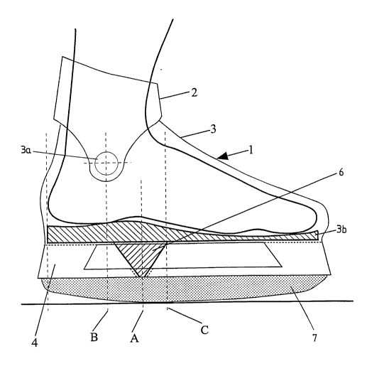
As shown in the drawings, according to Figures 1 and 2,
the ice skate according to the invention substantially
comprises a boot 1 with a leg portion 2 articulated by
means of two pivots 3a adjacent the location o~ the ankle
to a ~oot portion 3 having a downwards directed extension
in the form of a substantialy U-shaped support 4 for a
runner blade 7 of arcuate shape mounted with its concave
side facing upwards.
Accommodated within ~oot portion 3 is an insole 3b
provided on its lower side with a prop 7 o~ substantially
frustopyramidal shape with its greater base secured to
insole 3b by screws 5 and its smaller base taking support
on runner blade 7. Prop 6 extends from foot portion 3
through a correspondingly shaped aperture ~ormed in the
sole and provided with a sealing gasket (not shown in the
drawings).
The vertical axis A of prop 6 is disposed between
vertical axes B and C passing respectively through the
WO96101671 PCT~P95/02227 ~
217~5~2
ankle and the point extremity of runnerblade in relation of
the foot/boot.
Insole 3a and prop 6 are made of a plastic material
substantially more rigid than the material used for foot
portion 3 and support 4. In other cases prop 6 may be made
of a metallic material such as al~ nllm or the like.
It is evident that thanks to the positioning of prop 6,
the thrust forces exerted by the skater on insole 3b are
transmitted to runner blade 7 at the optimum location, and
that even when the skater does not assume the perfectly
correct skating attitude.
In the embodiment illustrated in Figure 3, insole 13b
has its lower side provided with two props 16 and 16', with
the vertical axis of prop 16 disposed the axis passing
through the ankle and that passing through the point of
extremity of runnerblade in relation of the foot/boot and
the vertical axis of prop 16', passing through the toe end
of the foot. This ice skate lends itself particularly well
for use in figure-skating.
In the embo~;m~nt illustrated in Figure 4, insole 23b
of the foot portion 23 of the boot 21 is formed with a
longitll~; n~l ly extended slot opening 23c ~or receiving
therein the screw 25 for fixing prop 26 on the underside.
This embodiment permits prop 26 to be longitll~i n~l ly
displaced to thereby vary its point of attack. Point of
transmission of thrust on blade in relation with ankle and
extremity of blade.
In the embodiment illustrated in Figure 5, there is
arranged between the lower surface of the sole 33g of the
boot 31 and the top surface of the support 34 of runner
blade 37 at the locations of the toe 33d and heel 33e
portions of the foot portion 33 sole reinforcement 36 with
appendix, triaungular or pyramidically shaped which
concentrates the effort in a well definite point. In this
case sole reinforcement 36 has a sharply bent profile
permitting it to take support on runner blade 37 at a
location between the vertical axes passing through the
~ WO96/01671 2 1 7 0 5 ~2 PCT~P95/02227
ankle and through the point of contact between the runner
blade and the ice in resting position. As it is shown in
Figure 5 axis A crosses the lowest point of insole 33b.
Furthermore it is also shown in this Figure that the insole
33b is fastened to the toe and heel portions 33d and 33e
respectively of the boot 33 by means of rivets 33f.
It should be noted that in the embodiments according to
the Figures 3 and 5 the articulation of the leg portion on
the foot portion is not shown. Nevertheless, these variants
can contain also articulations adjacent the location of the
ankle as it is disclosed in connection with the embodiments
in Figures 1 and 3.
As shown in the drawings according to Figures 6 and 7,
the roller skate according to the invention substantially
comprises a boot 41 composed of a leg portion 42
articulated by means of two pivots 43a adjacent the
location of the ankle to a foot portion 43. To the sole of
boot 41 as a base plate 48 has attached thereto by means of
screws 4S a substantially rigid prismatic extension 46
formed as a forked bracket for mounting a roller wheel 47
rotatable about a pin 49.
Attached to the sides of extension 46 are as a support
two parallel rigid bars 48 of suitable configuration and
interconnected by pins 49' for mounting rollers 47' in
longitl~; n~l alignment with roller 47.
In particular, the vertical axis A of extension 46 is
disposed at a location between vertical axes B and C
passing respectively through the ankle of the foot and
through the longitll~; n~l center of the boot.
It is evident that thanks to the positioning of
extension 46, the thrust exerted by the skater on sole as a
base plate 48 is transmitted directly to the roller (wheel)
47 and so, indirectly, via mentioned parallel rigid bars 44
to the other rollers (wheels) 47~ m~mi zing the
thrust/transmission on roller (wheel) 47 and that even when
the skater does not assume the perfectly correct posture
for skating.
WO96/01671 PCT~P95/02227
~. ~
2 ~ 2
In the embodiment illustrated in Figure 8, boot Sl is
mounted on a base plate 58 itself fixedly connected to
extension 56 acting as the mounting support for roller 57
and having the parallel bars 54 for mounting further
rollers 57' attached thereto each roller 57' rotatable
arranged about a pin 59'.
Extension 46 could be termitted to displacement in
longitllAi n~l and transversal direction in relation with the
boot/foot by regulation type, mentioned before (see Fig.4)
by extension slots or various holes permitting to attach
extension 46 in different positions on base plate 40' by
screws 45. This all for optimizing and personalizing the
user's way of skating and so improving skating performance.