Note: Descriptions are shown in the official language in which they were submitted.
WO 95/08661 217 0 51~ pcT/uss4lo4sns
PUFFED INSULATIVE MATERIAL
AND METHODS FOR MAKING SUCH MATERIAL
BACKGROUND OF THE INVENTION
1. Field of the Invention
The present invention relates to insulative fabric materialsand particularly to thermally insulative fabric materials having
substantial loft.
2. Description of Related Art
lo It is recognized that the ability of an insulative layer to
entrap a large amount of air improves its thermal insulative
properties. Until recently, some of the best materials to provide
these properties were natural insulations, such as wool or
feathers.
lS While natural insulations have many advantages, these
materials likewise have many deficiencies. Wool is heavy, it is
prone to odor, it is uncomfortable against one's skin, and it has
limited loft. On the other hand, feathers and down are lofty and
warm when dry, but are easily compromised by damp, they are
expensive and difficult to contain, their loft is easily lost, and
they cause allergic reactions in some.
To address some of these concerns, various synthetic
insulations have been developed. Many of these products comprise
polymer fibers or fabrics which effectively hold warmth by
entrapping air within their mesh, yet are easy to use, light,
durable, hypoallergenic, non-odor forming, and sometimes
breathable. Examples of such materials are sold by Minnesota
Mining and Manufacturing Co. (3M), of St. Paul, Minnesota, under
the trademark THINSULATE, and by E. I. duPont de Nemours and
30 Company (Dupont), of Wilmington, Delaware, under the trademark
THERMOLITE.
While these materials are successful in part, they continue to
suffer from a number of deficiencies. Synthetic insulations still
lack the high loft which has for so long been coveted. Loft can be
produced, but it is often at the cost of many layers of material
~U~ST~TU~E S3~ET (RULE 26~
WO 95/08661 ~ PCT/US94/04909
21 7 ~ 2
with intrinsic added weight. Furthermore, many synthetic
insulations lack resilience to deformation--losing warmth when mass
is applied against them.
In an effort to improve these properties, further development
efforts have continued. United States Patent 4,118,531, granted to
Hauser October 3, 1978, teaches that a batting or webbing of
polyester or polypropylene microfibers (around 10-15 microns in
diameter) can be produced with good thermal properties. To brace
these fibers against compression, a larger crimped fiber is
incorporated into the microfiber batting to improve resilience and
reduce matting of the fibers over time. Nonetheless, the amount of
resilience to deformation of this composite is limited to the bulk
fiber's ability to maintain its crimp. Additionally, the bulk of
these fibers is believed to restrict their useful applications.
Still another improvement in fiber loft is sought, this time
in a stretchy fabric materlal, in United States Patent 4,551,378
issued November 5, 1985 to Carey, Jr. Bicomponent fibers are
taught which can be crimped and bonded together. However, further
improvement in resillent loft ls stlll believed possible.
In WIPO Application WO 93/00390, published 7 January 1993,
owned by 3M, energy expandable microspheres are mixed with a
fibrillated polyolefin matrix suspenslon and then expanded to
produce a thermally insulative membrane. With the expandable
microspheres embedded in fibrlls of the fibrillated polyolefin, an
expanded polyolefin sheet material is produced by applying energy
to expand the microspheres. A light, breathable, thermally
~nsulative material can be produced using this process. Moreover,
the insulative material produced is quite resilient to deformation.
Regretfully, the processing of insulation in the manner taught
by WO 93/00390 continues to be constrained. To be effective, a
fibrillated polyolefin is required, inasmuch as expansion of the
insulatlon ls dependant upon embedding the expandable microspheres
within the linked microscopic fibrils of such material. More
burdensome is the fact that presently available microsphere
technology is keenly limlted in its temperature range--with
deterioratlon or complete destruction of the microspheres normally
occurring at temperatures above about 200C when exposed for more
than a few minutes. Such temperature limltations restrict many
=
`` 217~
3
desirable processing steps, such as sintering, which would otherwise be
advisable with a polymer material alone.
Accordingly, it is a primary purpose of the present invention to
produce an insulative material that is lightweight, durable, highly thermally
5 insulative, and resilient to deformation.
It is another purpose of the present invention to produce an insulative
material that retains signihcant thermal insulative properties even when wet
or placed under compressive force.
It is still another purpose of the present invention to produce an
10 insulative materiai that provides resilient properties with a wide variety of insulative materials.
It is a further purpose of the present invention to produce an insulative
material that provides resilient properties of thermoplastic microspheres
without limiting the initial processing procedures for the insulative materials.These and other purposes of the present invention will become
evident from review of the following specification.
SUMMARY OF THE INVENTION
The present invention is an insulative material with improved loft
20 properties and methods to produce such insulation. In a basic form, the
present invention embeds resilient thermoplastic microspheres within
existing multiple-layered insulation. The microspheres are retained in the
insulation by one of a number of disclosed structures and methods to
prevent microsphere migration out of the insulation. Among the strategies
25 for containing the microspheres are: including microsphere-impermeable
barrier fabric surrounding the insulation, with the microspheres loosely
contained within a confned cell; providing an enmeshing insulative matrix
entrapping the spheres; and/or causing adhesion of the spheres within the
insulation.
While adding little additional weight to the insulation material, the
resilient microspheres help to maintain the loft of the insulation during use
and to restore loft even after being signifcantly compressed. As a result,
numerous properties of the insulation are improved, including thermal
insulation (even when wet), resilience to deformation, and compression
35 resistance
AM~N~ SilEE~
WO 95/08661 PCT/tJS94/04909
2 1 ~ 4
Ideally, expandable microspheres are employed which are
motivated into the insulation through pores in a barrier layer or
layers. Once in place, the expandable microspheres are expanded to
a size too great to fit back through the pores in the barrier
s layer. In this manner, virtually any form of existing insulation
material can be readily provided with the improved loft properties
of the present invention--even after the insulation material has
been incorporated into a final form. As a result, the process of
the present invention is not handicapped by tight constraints on
the type of insulation material which can be employed or the
present limitations on processing conditions under which expandable
microspheres may be used.
DESCRIPTION OF THE DRAWINGS
The operation of the present invention should become apparent
from the following description when considered in conjunction with
the accompanying drawings, in which:
Figure 1 is a cross-sectional view of one embodiment of an
insulation material of the present invention;
Figure 2 is a cross-sectional view of another embodiment of an
insulation material of the present invention;
Figure 3 is a three-quarter isometric view of conventional
quilted insulative material employed as initial substrate for the
present invention;
Figure 4 is a side view of insulative material mounted on a
vacuum apparatus employed in the present invention, the insulative
material including a layer of unexpanded expandable thermoplastic
microspheres thereon;
Figure 5 is a three-quarter isometric view of a high-loft
quilted insulative material of the present invention;
Figure 6 is a cross-sectional view of one embodiment of a
multiple layered insulative material of the present invention;
Figure 7 is a cross-sectional view of another embodiment of a
multiple layered insulative material of the present invention;
Figure 8 is a graph depicting the amount of resistance to
3s compression of two samples of insulative material of the present
2i7~
invention as compared with conventional insulative material;
Figure 9 is a schematic representation of one proposed embodiment
of apparatus for intermixing a spray of microdenier fibers and microspheres
for use in the present invention;
Figure 10 is a cross-sectional view of another embodiment of an
insulation materiai of the present invention wherein the microspheres are
retained within the insulation without a barrier layer; and
Figure 11 is an enlarged view of a microsphere bonded to surrounding
insulative fibers.
DETAILED DESCRIPTION OF THE INVENTION
The present invention comprises an insulative material with improved
loft characteristics and method for producing such material.
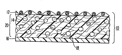
As is shown in Figure 1, in its simplest form, the present invention
1~ comprises layered insulation material 10 made from conventional multiplelayers 12, 14, 16 of fabric material, into which resilient thermoplastic
miorospheres 18 are incorporated. The microspheres 18 are restrained
within the material by containing them in a cell 20 defined between barrier
layers of material 12, 16.
The key to the present invention is to retain microspheres within
conventional insulation during normal use. To this end, a number of
strategies can be employed. As is shown in Figure 1, barrier layers 12, 16
can be provided co""~ i"g sufficiently closed structure that the
microspheres cannot pass through them during normal use. In this case,
the microspheres are loosely contained within a confined space of the cell.
The barrier layers may be part of the original material of the insulation or
may be a separate layer or layers of material applied on top of or between
existing insulation layers. Other methods discussed below for retaining the
microspheres within the insulation include providing a sufficiently entangled
mesh of insulative fibers that the microspheres will not migrate out of the
insulation once installed therein, and/or adhering the microspheres within
insulative fibers to prevent their separation from the insulation.
AME~ D S~5EET
WO 95108661 PCT/US94/04909
2170~1~ 6
The microspheres produce a substantial loft in the material
which is highly resilient to compression. The amount of loft and
resilience is readily adjusted by varying the amount, type, size,
and amount of "puff" of microspheres present in the insulation.
Preferably, the microspheres comprise expandable thermoplastic
microspheres, such as those available from Nobel Industries Sweden,
of Sundsvall, Sweden, under the trademark EXPANCEL. Such
microspheres comprise a thermoplastic shell entrapping a volatile
liquid, such as isopentane. When subjected to heat or similar
0 activation energy, the microspheres dramatically expand to many
times their original size and retain such size when the activation
energy is removed. The process for producing such material is
explained in United States Patent 3,615,972 issued October 26,
1971, to Morehouse et al.
Expandable microspheres are commercially available in a
variety of sizes and forms, with initial expansion temperatures
generally ranging from 80 to 130C. Expansion can usually be
practiced between about 80 to 260C or above, depending upon a
number of factors, such as dwell time. A typical EXPANCEL
microsphere has an initial average diameter of 9 to 17 microns and
an average expanded diameter of 40 to 60 microns. According to
Nobel Industries, the microspheres have an unexpanded true density
of 1250-1300 kg/m3 and an expanded density below 20 kg/m3.
As presently contemplated, the preferred microspheres for use
in the present invention have the following properties: low
density; resilience to deformation; expandable on demand; an
average expanded size of at least 15 microns; and an expansion
ratio of at least 1.5:1. Additionally, pre-expanded microspheres
suitable for use in certain embodiments of the present invention
are also commercially available from Nobel Industries under the
designation EXPANCEL (e.g. type DE-091). Pre-expanded microspheres
are also available from a number of other sources, such as under
the product name DUALITE from Pierce h Stevens of Buffalo, New
York.
The presently preferred method of producing insulation in
accordance with the present invention is to use an initial
insulation material including a barrier layer on at least one side
having a porous structure, such as that shown in woven barrier
WO 9S/08661 7 2 ~ 7 0 ~ ~ ~ PcT/usg4lo~gn9
layer 12. The porous barrier layer 12 should be selected with a
pore structure large enough to allow unexpanded microspheres to
pass easily into cell 20, but small enough to resist escape of
expanded microspheres from the cell 20.
In operation, unexpanded expandable microspheres are motivated
through the porous barrier layer 12 into cell 20. Such motivation
can occur through any appropriate means, such as through use of a
pressure differential, drawing unexpanded microspheres into the
material through use of a partial vacuum generated in the
insulation material and/or forcing the spheres into the material
through use of air or other mechanical pressure. Other suitable
means for inserting the microspheres before expansion include:
incorporation of the microspheres within the cell area during the
manufacturing process (e.g. through spraying or similar process);
driving the microspheres into the insulation via centrifugation;
etc.
As the term "cell~ is used throughout this application, it is
intended to encompass any confined space which resists the movement
of microspheres through or out of the insulation. Ideal cells
should be small enough to assure even loft throughout the
insulation material (e.g. approximately 1 to 3 cm squares).
However, depending upon the types of insulation material and
microsphere materials used, the cells may take virtually any size
and shape, including merely the outline of the entire insulation
material, w~thout necessarily limiting its effectiveness.
Once the microspheres are placed within the structure of the
lnsulation, activation energy is applied to the material to cause
the microspheres to enlarge. The enlarged microspheres 18 then are
trapped between the barrier layers 12, 16, separating the barrier
layers from one another and providing loft to the fabric material.
It should be understood that the use of ~he term "expandable
microsphere~ herein is intended to encompass any hollow resilient
container f~lled with volatile fluid which is adapted to expand
(i.e. before, during or after incorporation within the insulation).
e 35 Although presently available microspheres are essentially ball-
shaped partlcles adapted to expand when exposed to an energy
source, it should be understood that such microspheres are quite
resilient in their expanded form and it may be possible to compress
WO 95/08661 PCT/US94/049119
2~7~5~ 8
and release the microspheres to achieve the expansion required for
the present invention. Additionally, it may be possible to form
such microspheres in a variety of other shapes, such as tubes,
ellipsoids, cubes, particles, etc. As such, the term "expandable
microspheren in the context of the present invention is intended to
include all applicable forms and uses of these products now known
or later developed.
In one presently preferred embodiment of the present
invention, EXPANCEL type 091 DU is employed. This product
0 comprises an off-white dry powder with a particle size between 5
and 50 microns. The shell of the microsphere comprises
acrylonitrile or methacrylonitrile. The volatile liquid comprises
isopentane.
In the embodiment shown in Figure 1, the second barrier layer
16 is a continuous sheet of material having little or no porous
structure, such as a polyurethane coated fabric material (e.g.,
that available from W. L. Gore & Associates, Inc., of Elkton,
Maryland, under the trademark GORE-TEX~). As should be evident, in
an instance where the second barrier layer 16 is impervious to air
flow, such as with a sheet of polyethylene or similar plastic or
polyurethane coated GORE-TEX~ fabric, the introduction of
microspheres under a pressure differential is dependent upon
sideways flow of air through the insulation material to provide
sufficient draw of the microspheres into the cell 20.
2s An alternative embodiment of the present invention is shown in
Figure 2 wherein a first barrier layer 22 is again provided in the
form of a woven material. Second barrier layer 24, however, is a
porous membrane, such as a membrane of expanded
polytetrafluoroethylene (PTFE), having micropores 26 therein. The
porous nature of this second barrier layer 24 provides another
avenue for the introduction of microspheres and/or improved means
to provide pressure differential flow through the material. For
many applications, the second barrier layer 24 may simply be
constructed from the same material as the first barrier layer 22.
In the above described method where microsphere penetration is
required, preferred barrier layers for use with the present
invention comprise a material with sufficient porosity to allow
unexpanded microspheres to pass therethrough, but of sufficiently
WO 95/08661 21 7 0 ~1~ PCT/US94/04909
9
restricted porosity to prevent expanded micropsheres from passing
therethrough. Another suitable barrier layer is CAMBRELL fabric,
available from Camtex Fabrics Ltd. of Workington, Cumbria, United
Kingdom. This material is a multi-filament non-woven material
manufactured from a blend of type 6 and type 66 nylon fiber. It
has a general porosity (i.e., openings) of about 1-10 microns
across.
In both of the embodiments of Figures 1 and 2, multiple layers
of insulative fabric 14 are provided within the cell 20 between the
lo first and second barrier layers. Common insulative material in
this regard include: synthetic fibers such as acrylic, polyester,
polypropylene, polyethylene, polyolefins, RAYON, polyamindes,
acetates, etc.; synthetic fabrics such as woven or non-woven
materials made from any of the above fibers; and/or natural
insulators such as wool fiber or weave, feather/down, cotton fibers
or fabrics, silk fabrics, etc.
The ideal insulative layer 14 comprises an open structure
through which the microspheres can read~ly intersperse and in which
the microspheres can become entrapped once enlarged. Preferred
insulative layers comprise microdenier fibers of polyester,
polyolefin, polyethylene, or similar materials and/or blends
thereof. Preferably, the materials comprise entangled microdenier
fibers which are discrete and unconnected elements, such as the
structure found in THERMOLITE insulation available from DuPont
comprising polyester fibers, or THINSULATE insulation available
from ~M comprising a blend of polyester and polyolefin fibers.
Other commercial insulation materials which may be suitable
for use with the present invention include: AEROZIP polyester
insulation available from Toray; HOLLOFIL hollow polyester fiber
insulation available from Dupont; POLARGUARD continuous filament
fiber insulation available from Hoechst Celanese; POLARTEC
insulation available from Malden Mills; PRIMALOFT microfiber
insulation available from Albany International; QUALLOFIL hollow
polyester flber available from Dupont; THERMALON olefin insulation
with polyester batting available from Thermalon Industries;
THERMORE polyolefin/polyester/resin blend insulation available from
FISI/Concept III; TREVIRA LOFT nine denier polyester staple fiber
insulation available from Hoechst Celanese; and ULTRFIBRE reflected
WO 95/08661 PCT/US941049Q9
2~7a~2 1 o
metal plated fiber insulation available from Ultrafibre, Inc.
Additionally, as has been explained, the present invention may also
be incorporated with a variety of natural insulation materials,
such as wool fibers or down.
The use of an intermediate insulative layer or layers is
preferred for a number of reasons. First, the insulative layer
provides the primary areas for containment of insulative air.
Although the insulative layers can be provided on the outside of
one or both of the barrier layers, the loft characteristics of the
lo present invention are far better enhanced by including at least
some insulative material within the cell 20 which can be "puffed
up" by the microspheres.
Second, the microspheres are believed to function far better
in the present invention if some network is included to prevent the
microspheres from flowing unrestrained through the cell 20. This
concern is vastly increased where large cells are used in which the
microspheres will tend to conglomerate at a lowest point during
use.
One general example of a possible process of installing
expandable microspheres into an existing insulation material is
shown in Figures 3 through 5. Figure 3 shows a conventional
multiple layered insulation material 28. This material comprises a
top fabric layer 30, multiple intermediate fabric layers 32, and a
bottom layer 34. Suitable insulation material for use in this
embodiment includes THINSULATE insulation available from Minnesota
Mining and Manufacturing Company. The insulation can then be
attached to a backing material, such as a CAMBRELL fabric
(previously discussed) with a pore structure of entangled
overlapping nylon fibers and typical openings of about 1 to 10
microns. For improved operation in the present invention,
stitching 36 has been provided through the material in a
conventional quilted-fashion. Each rectangle 38 of the quilt
pattern will define one cell of the present invention.
In order to motivate expandable microspheres into the
insulation, a pressure differential must be established. To this
end, the initial insulation material 28 can be placed on an
apparatus 40 capable of generating a partial vacuum within the
insulation. In the apparatus 40 shown in Figure 4, the insulation
WO 95tO8661 217 ~ PCT/US94m4909
1 1
material 28 is placed on a plate 42 having numerous holes (not
shown) therein in fluid communication with the insulation material
Z8. A vacuum line 44 is connected to the plate to pull air from
the insulation material via the holes.
- 5 A layer 46 of microspheres is spread evenly across the top
layer 30 of the insulation 28. By way of illustration, a layer of
- expandable microspheres in a granular form, such as EXPANCEL brand
microspheres, type DU-091, acquired from Nobel Industries Sweden,
can be spread in a layer comprising about 10 to 100 g/cm2.
lo A vacuum of about 100 mm Hg at 0C is applied to this material
for a period of about 1 to 15 seconds until a significant amount of
the microspheres have been aspirated into the material. Excess
microspheres then can be wiped or blown from the surface.
Alternatively, various powder dispensing systems can be used to
apply the expandable microspheres on a continuous basis.
Formed in this manner, the insulation loaded with microspheres
is subJected to heat or other activation energy to cause the
microspheres to expand in place. For example, placing the loaded
insulation material in a convection oven set at about 150 to 260C
for a period of about 1 to 15 minutes. Once expanded, the final
product 48 will assume a puffed form such as that shown in Figure
5.
Further alternative constructions of the present invention are
shown in Figures 6 and 7. Figure 6 illustrates an unexpanded
insulation 50 having as barrier layers its two outermost surfaces
52, 54. Multiple layers of insulation 56a, 56b, 56c, 56d are
positioned between the barrier layers. In this construction, the
microspheres should be randomly spread between the two barrier
layers 52, 54, inter-meshed within the intermediate layers 56a-56d.
A somewhat different construction of insulation 58 is shown in
Figure 7. In this embodiment, barrier layers 60, 62 are embedded
within the material, with other layers 64, 66 positioned on the
oltside of the barrier layers. One purpose of this construction
might be to allow for the introduction of outer layers of specific
utility (e.g. more durable materlal, waterproof material,
impermeable ~aterial, etc.) which can better protect the barrier
layers 60, 62 and the insulation. Additionally, as has been noted,
additional insulation layers 68, 70 may be included on the outside
WO 95/08661 PCT/US94/04909
2 ~ 7 ~ 2
of the barrier layers 60, 62 to address specific operational needs.
Without intending to limit the scope of the present invention,
the following serve as examples of how the present invention may be
practiced:
EXAMPLE 1:
Insulation material purchased from Minnesota Mining and
Manufacturing Co. (3M) under the trademark THINSULATE\ was modified
by sewing a supporting material of CAMBRELL fabric to one side
using a quilting pattern as is commonly done in the apparel
lo industry. The THINSULATE insulation comprises a
polyolefin/polyester mixture of microfibers (reported to be a blend
with a ratio of approximately 65:35). A 33 x 33 cm (13" x 13n)
sheet of supported THINSULATE having a total thickness of 0.300 cm
(0.118n) and weighing 40.55 9 was then impregnated with unexpanded
thermoplastic microspheres available from Nobel Industries under
the tradename EXPANCEL, Type DU-091. The technique utilized for
impregnating the THINSULATE was as follows:
1. 2.35 grams of EXPANCEL DU-091 was evenly sifted on top of
the non-fabric surface of the supported THINSULATE material.
2. The underside of the material was then subjected to a
vacuum source from a conventional commercial shop vacuum cleaner.
This drew in and distributed the unexpanded EXPANCEL powder
throughout the thickness of the material.
3. The impregnated material was then placed in a convection
oven at 180C for 3 minutes in order to expand the microspheres and
puff the insulation.
4. The excess microspheres were then removed from the
surface of the material with an air jet.
The puff material had a final thickness of 0.465 cm (0.183")
and weight of 42.15 9. This calculates to a thickness increase of
55% with a weight increase of only 3.9%. The material exhibited a
greatly improved resistance to compression and a more resilient
nature than the original untreated material.
A thermal conductivity test was then performed on the above
puffed sample and a non-modified supported THINSULATE sample. A
WO 95/08661 21 7 0 51~ PCT/US94/04909
13
sample of each measuring 30.5 x 30.5 cm (12 inches) square was
tested according to ASTM CS18 procedures using the Holometrics
Rapid K Thermal Conductivity Instrument Model RK 80. A constant
20C water bath was supplied.
- 5 The equation used to calculate thermal conductivity (~) of an
unknown measured in BTU-INCH/(HR-FT2-F) is as follows:
[(Q)(~x)(~T)c(~T)] ~ [(Q)c(~x)c(~T)] where:
~c - thermal conductivity of calibration sample
Q 8 total heat flow
~X - thickness of sample
~T ~ temp of hot face - temp of cold face
( )c ~ calibration sample
~T for testing was 30C with the upper face at 60C and the
lower face at 30C.
Thermal conductivity (~) for the puffed sample was calculated to be
8.928x10⁻⁵ cal/((s)(cm)(C)) (i.e. 0.259 BTU-INCH/(HR-FT2-F)).
The non-modified supported THINSULATE sample had a calculated value
of 8.892x10⁻⁵ cal/((s)(cm)(C)) (i.e. 0.258 BTU-INCH/(HR-FT2-F))
EXAMPLE 2:
Another 33 x 33 cm (13~ x 13~) sheet of supported THINSULATE
having a total thickness of 0.300 cm (0.118~) and weighing 39.87 9
was then impregnated using 7.05 9 of EXPANCEL DU-091. The same
technique as Example 1 was used for impregnating the THINSULATE
insulation.
After heating, the puffed material had a final thickness of
0.706 cm (0.278~) and weight of 44.85 9. This calculates to an
increase in thickness of 135% and weight increase of only 12.5Y
The material exhibited an even greater improved resistance to
compression and a more resilient nature than the sample of Example
1.
A test for thermal conductivity (~ was conducted as in
Example 1. The sample calculated to be 9.135x10⁻⁵
cal/((s)(cm)(C)) (i.e. 0.265 BTU-INCH/(HR-FT2-F)).
WO 95/08661 . PCTIUS9~/04909
2~7~51~ 1 4
EXAMPLE 3:
A 27 x 15 cm (10.5" x 5.75") sheet of THINSULATE insulation
having a total thickness of 0.541 cm (0.213") and weighing 8.52 9
was impregnated using 2.90 9 of EXPANCEL DU-091. The THINSULATE
insulation was unsupported (i.e. it had no separate backing
material applied to it). The same technique as Example 1 was used
for impregnating the THINSULATE insulation.
After heating, the puffed material had a final thickness of
1.481 cm (0.~83n) and weight of 10.27 9. This calculates to an
0 increase in thickness of 174X and a weight increase of only 20.5Y,.
The material exhibited a greatly improved resistance to compression
and a more resilient nature than the untreated sample.
EXAMPLE 4:
A 30.5 x 30.5 cm (12" x 12n) sheet of supported THERMOLITE~
insulation commercially available from E. I. DuPont de Nemours and
Co., Wilmington, Delaware, having a total thickness of 0.381 cm
(0.150n) and weighing 36.95 9 was impregnated using 7.00 9 of
EXPANCEL type DU-091. The THERMOLITE insulation comprises fine
denier polyester fibers. The same technique as Example 1 was used
for impregnating the THERMOLITE insulation.
After heating, the puffed material had a final thickness of
0.754 cm (0.297~) and weight of 41.40 9. This calculates to an
increase in thickness of 98% and a weight increase of only 12.0X
The material exhibited a greatly improved resistance to compression
and a more resilient nature than the untreated sample.
EXAMPLE 5:
A moisture vapor transmission rate test (MVTR) was conducted
on the puffed modified supported THINSULATE and the non-modified
supported THINSULATE samples of Example 1. This test apparatus
consists of a reservoir filled with distilled water maintained at
23C. The reservoir is covered by a porous expanded
polytetrafluoroethylene (ePTFE) membrane having a high moisture
vapor transmission rate (MVTR). Cups having a mouth diameter of
8.9 cm (3.5~) are prepared by partially filling the cup with
potassium acetate and then covering the mouth of the cup with the
same high MVTR ePTFE membrane. Samples to be tested are then
WO 95/08661 1 5 ~ 1 7 ~ ~ 1 2 PCT/US94/04909
placed on the membrane covering the reservoir and weighed cups of
the potassium acetate are placed membrane side down onto the
samples. A weighed control cup of potassium acetate is placed
membrane side down directly onto the reservoir membrane. After 30
minutes, the cups of potassium acetate are weighed. The weight
gain is calculated and then MVTR expressed in [(gm/meter2)/24
hours] is calculated using the following formula:
MVTR ~ [weight gain (gm)] x [433960/Test time(min)]
The MTVR results of this test were:
SAMPLE AVERAGE (OF 3) STD. DEV.
PUFFED 448 148
NON-MODIFIED 1165 29.1
EXAMPLE 6:
A compressive force was applied to 30.5 x 30.5 cm (12" x 12")
cut samples of Examples 1 and 2. The thickness was measured at
various load levels. The percentage of original thickness was
calculated and plotted as a function of compressive load. The
results of this test are shown in the graph of Figure 8. As can be
seen, the modified samples, represented by lines 72 and 74, show a
far greater resistance to compression than the unmodified sample,
represented by line 76.
~ ithin the scope of the present invention there are various
alternate methods contemplated for incorporating expandable
microspheres within a matrix of insulation. Some examples of such
alternate methods are described below:
PROPOSED E%AMPLE 7:
Expandable microspheres, such as EXPANCEL type DU-091, can be
Jirectly sprayed onto a fibrous webbing of insulation during
fabrication. To this end, spray apparatus such as that disclosed
in United States Patent 4,118,531 issued October 3, 1978, to Hauser
may be employed.
One proposed apparatus for this procedure is illustrated'in
WO 95/08661 ` ~ PCTIUS94/04909
2 ~ 6
Figure 9. In this apparatus, a continuous web of substrate
material 78 is pulled past microfiber blowing apparatus 80 and
microsphere blowing apparatus 82. Blowing apparatus 80 deposits a
layer of microfibers 84 on the substrate 78 in the manner described
in United States Patent 4,118,531. Simultaneously, blowing
apparatus 82 can intermix a stream of expandable microspheres 86
into the microfibers 84 to produce a blended microfiber/microsphere
layer 88 on the substrate. To impart some of the additional the
propertiee taught in United States Patent 4,118,531, a stream of
lo crimped fibers 90 may likewise be intermixed into
microfiber/microsphere layer 88 through the use of lickerin roller
apparatus 92.
In this manner, the expandable microspheres should become
entangled within the structure of the insulation and should remain
within the mesh of the completed insulation once expanded even
without the use of a specific barrier layer to prevent movement of
the expandable spheres.
After the web of insulation is configured, the impregnated
material can be placed in a convection oven or similar heating
means at about 180C for about 3 minutes in order to expand the
microspheres and puff the insulation. Once formed in this manner,
the final insulation is contemplated to form a structure such as
that shown in Figure 10.
Alternatively, due to the automatic mixing which occurs
through the method illustrated in Figure 9, pre-expanded spheres
may likewise be used in this process without the need for an
expans~on step with equally good insulative results expected.
As is illustrated in Figure 10, the completed insulation
should comprise a mesh of insulative fibers 94 with expandable
microspheres 96 entrapped therein.
EXAMPLE 8:
To achieve better amalgamation of the microspheres within the
insulation material, it may also be useful to adhere the
microspheres to surrounding insulation material. One possible
approach in this regard is to. expose the microspheres and the
insulation to sufficient heat to bond the fibers to the
microspheres. For convenience, this bonding can occur using the
WO 95/08661 217 ~ PCT/US94/04909
t7 . ;~
same or a similar heating process described in above Proposed
Example 7 for expanding the microspheres in place. For example, it
has been shown that heating for 2 minutes at about 260C is
adequate to bond EXPANCEL type DU-091 microspheres to polyester
andjor polyolefin fibers. As is shown in Figure 11, when heated in
this manner, the microspheres 96 will begin to soften and the
fibers 94 will begin to adhere within the softened microspheres.
The areas of adhesion 98a, 98b, 98c, 98d bond the microspheres in
place relative to the surrounding insulative fibers and prevent
migration of the spheres.
In place of or in addition to the heating process, an adhesive
may also be added to the spheres and/or the fibers to assist in
holding the microspheres in place. This process is particularly
applicable where the microspheres are installed within the
15 insulation during the fabrication process for the insulation
itself.
Where fabrication of the insulation comprises the injection of
the microspheres through existing insulation, it may be possible to
coat the microspheres with a heat activated adhesive or a pre-
20 cursor to an adhesive and then apply heat or add an activatingagent once the microspheres are in place to hold their position.
Alternatively, an adhesive may be added to the insulation material
after the microspheres are installed.
It should be clear from the above examples that insulation
made in accordance with the present invention demonstrates a very
distinct improvement over conventional insulation materials. The
introduction of expandable microspheres in the manner described
introduces little add7tional weight yet provides greater thermal
insulative properties, greater compression resistance, and better
resilience. Additionally, the added loft produced by the
microspheres in the present invention is not particularly affected
by repeated compression of the insulation material. Further, this
- loft should resist the flattening effect of wet fibers, which can seriously compromise some existing insulations.
Moreover, unlike previous attempts to combine expandable
microspheres with fibrillated polymers during the chemical
2 i7~ PCTIUS9~/049(~9
1 8
processing steps of the insulation material, resilient insulative
material made in accordance with the present invention can be
combined with virtually any existing insulation material. This
permits utilization of the benefits of expandable microspheres
without limitation concerning insulation's particular chemical
structure or its processing steps.
Areas where the present invention may be of particular use
include: all forms of outdoor clothing (e.g. hats, jackets, shoes
and boots, gloves, etc.); all ~orms of outdoor equipment (e.g.
0 sleeping bags and pads, seat pads, etc.); household and industrial
thermal insulation materials; etc.
While particular embodiments of the present invention have
been illustrated and described herein, the present invention should
not be limited to such illustrations and descriptions. It should
be apparent that changes and modifications may be incorporated and
embodied as part of the present invention within the scope of the
following claims.