Note: Descriptions are shown in the official language in which they were submitted.
~ wo g /n~5~1 2 1 ~ Q ~, ~ 4 PCT~S~4~
~ANDLE REINFORCEMENT FOR A CARTON
Backqround of the Invention
The present invention relates generally to paperboard
cartons for use in packaging containers such as cans or
bottles for beverages. More particularly, the invention
relates to a reinforced handle for such cartons.
Containers such as cans or bottles for beverages
including soft drink, beer, juices and the like are commonly
sold in multiple quantities packaged in a paperboard carton.
For the convenience of the consumer, the carton is often
provided with a handle, which quite commonly includes as a
primary feature one or two slots or other apertures formed
in the carton. The user inserts the hand or fingers into
one or both of the slots to lift the carton. Many v~rieties
of handles are known in the art.
Lifting a carton containing beverage cans or bottles
introduces considerable stress into the paperboard from
which the carton is formed. For this reason, to prevent
tearing of the paperboard and failure of the carton, it is
known to design carton handles with various reinforcement
structures. This is often accomplished by providing two,
three or more layers of paperboard in the vicinity of the
handle slots.
Recently, attempts have been made to introduce into the
marketplace beverage cartons wherein cans are arranged in
two tiers, with corresponding cans from each tier being
axially aligned. An example of such a carton can be seen by
reference to US-A-5,234,102. Such cartons are intended to
hold relatively large numbers of cans, for example 24 to 36
cans. The contained weight of these cartons makes use of
reinforced handle structures particularly advantageous.
W095/06594 2 ~ 7 ~ 8 8 4 PCT/US~3,'0~986 ~
It is usually desirable to provide the handle
reinforcing flaps or panels as part of the blank for such a
carton, thereby to eliminate the need to manipulate multiple
pieces in the carton loading operation. A common way to
accomplish this is to provide lapped top panels at opposite
ends of the carton blank. To save some paperboard, one or
both of the lapped panels may comprise only a portion of the
completed top panel. An example of this type of handle
reinforcement may be seen in US-A-5,221,041.
However, especially a large carton such as the two-tier
example described above, a relatively large blank results
from this approach. Thus, it is important that the addition
of such reinforcing panels or flaps not significantly
increase the overall size of the carton blank. This is
especially true when considering the layout of blanks on the
paperboard web from which the cartons are manufactured,
where an increase in blank size can significantly increase
the amount of paperboard required.
What is needed, therefore, is a reinforced handle
structure wherein the reinforcement is accomplished using a
single-piece blank. The reinforcement structure should not
significantly increase the blank size. Rather, it should be
relatively compact to most efficiently use layout space on
the paperboard web from which the cartons are formed.
SummarY of the Invention
In accordance with one embodiment, the present
invention provides a carton for containers such as cans or
bottles including a top wall having opposed side edges and
opposed end edges and a pair of side walls. One of the side
walls is connected to each of the side edges of the top
wall, and a bottom wall is connected between the side walls
to complete a tubular structure. End closure structure
closes each end of the tubular structure, the end closure
structure including an end flap connected at a top edge to
~wo 95/oG5g4 2 1 7 a ~ 8 ~ PCT~S94/09986
each of the end edges of the top wall. Each of the end
flaps has a pair of side edges.
s A handle aperture is defined in the top wall and
positioned thereon generally centrally of the top wall. A
handle reinforcing structure includes a pair of end
portions, one of the end portions connected along one side
edge of each of the end flaps and extending to the top edge
thereof, and a central portion connected to each of the end
portions and extending therebetween. The central portion is
secured in overlapping relationship to the top wall and
positioned thereon to be substantially adjacent to a portion
of the handle aperture.
The top wall may have a pair of handle portions formed
therein. The central portion is then positioned on the top
wall to extend between the apertures, adjacent to a portion
of each of the apertures. The apertures may further be
disposed along the top wall on either side and equidistant
from a notional centerline extending between the end edges
of the top wall, the central portion being further
positioned generally along the centerline.
Preferably, each of the end flaps is narrower between
the side edges thereof than the top wall between the side
edges thereof. Each of the end portions of the handle
reinforcing structure may be connected to the central
portion along fold lines, and each of the end portions may
be connected to the end flaps along fold lines.
A reinforcing strip may be connected along a fold line
to the central portion of the handle reinforcing structure,
the strip being adhered to the central portion in
overlapping relationship to provide an additional ply for
the handle reinforcing structure.
Alternatively, the present invention may provide a
blank for forming a carton. The blank includes a bottom
W095106s94 ~ T ~ 8 g~ PCT~S91~0~6
panel having opposed side edges and a pair of side panels,
one of the side panels connected along a bottom edge to each
the side edge of the bottom panel. A top panel having
opposed first and second side edges and opposed end edges is
connected along the first side edge to one of the side
panels. One of a pair of end flaps is connected along its
top edge to each of the end edges of the top panel, each of
the end flaps further having first and second side edges
corresponding to the first and second side edges of the top
panel.
A handle aperture is defined in the top panel and
positioned thereon generally centrally of the top wall. A
handle reinforcing structure includes a pair of end
portions, one of the end portions connected along a fold
line to the second side edge to each of the end flaps. A
central portion is connected to each of the end portions and
extends therebetween generally along but separated from the
second side edge of the top panel. The end portions and the
central portion are arranged whereby upon folding of the end
portions along the fold lines into overlapping relationship
with the end flaps, the central portion is positioned in
overlapping relationship to the top panel to be
substantially adjacent to a portion of the handle aperture.
The top panel may have a pair of handle portions formed
therein, in which case the central portion is arranged to be
positioned on the top panel to extend between the apertures,
adjacent to a portion of each of the apertures.
Preferably, the second side edge of each of the end
flaps is inset on the end flaps with respect to the second
side edge on the top wall. Also, each of the end portions
of the handle reinforcing structure is preferably connected
to the central portion along fold lines substantially
aligned with the end edges of the top panel.
21 7~g.8~
WO95/06594 PCT~S94,~9~6
- 5 -
The handle reinforcing structure may also be provided
with a reinforcing strip connected along a fold line to the
central portion of the handle reinforcing structure. The
reinforcing strip is preferably positioned on the blank
between the central portion of the handle reinforcing
str~cture and the top panel.
The blank may also include a glue flap foldably
connected to the second side edge of the top panel. The
glue flap and the reinforcing strip are positioned on the
blank adjacent each other, and are separated, preferably by
a cut line.
Brief Description of the Drawings
Fig. 1 is a plan view of the inner surface of a blank
for forming a carton incorporating a dispenser in accordance
with the present invention.
Fig. 2 is a partial plan view similar to Fig. 1,
showing a first step in the formation of a carton from the
blank of Fig. 1.
Fig. 3 is a partial plan view similar to Fig. 2,
showing a fur~her step in the formation of a carton from the
blank of Fig. 1.
Figs. 4 and 5 are plan views of the blank of Figs. 1,
2 and 3, further illustrating the formation of the carton.
In Fig. 5, a portion of the end closure flap and top wall
panel are broken away.
Fig. 6 is a three-quarter view of the top, side and end
of an erected and loaded carton formed from the blank of
Fig. 1, showing the end closure structure prior to folding
and sealing.
W095/06594 2 t ~ Q 8 8 4 PCT~S94/09986 ~
Fig. 7 is a view similar to Fig. 6, but showing the end
closure structure sealed to form the finished carton.
Detailed Description of the Preferred Embodiment
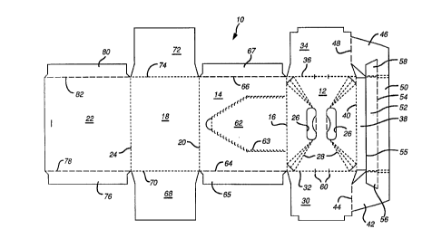
A carton lO for use in connection with the present
invention may be seen in blank form by reference to Fig. 1.
The carton includes a top wall panel 12 connected to a side
wall panel 14 along fold line 16. A bottom wall panel 18 is
connected to side wall panel 14 along fold line 20, and at
its opposite side is connected to side wall panel 22 along
fold line 24.
Top wall panel 12 includes a pair of hand apertures 26
for forming a portion of a handle structure for the carton.
Additionally, reinforcing fold lines 28 extend from
apertures 26 toward the corners of top wall panel 12, in
accordance with the handle structure disclosed in
US-A-5,307,932. However, other known arrangements of
reinforcing fold lines may be used. In some cases, the fold
lines may even be eliminated
A major end flap 30 is connected at one end edge of top
wall panel 12 along fold line 32, while a second major end
panel 34 is connected at the opposite end of top wall panel
12 along fold line 36. A glue flap 38 is connected to top
wall panel 12 along fold line 40.
A handle reinforcing structure in accordance with the
present invention is connected to each of major end flaps 30
and 34, and comprises end portion 42 connected to major end
flap 30 along fold line 44, and end portion 46 connected to
major end flap 34 along fold line 48. A central portion 50
interconnects end portions 42 and 46. An auxiliary handle
reinforcing strip 52 is connected to central portion 50
along a fold line S4. Reinforcing strip 52 is positioned
adjacent to glue flap 38, separated therefrom along a cut
line 55.
~WO 95/06594 2 1 7 0 8 8 4 PCT/US94/09986
- 7 -
Auxiliary reinforcing strip 52 includes end flap 56
which extends into end portion 42, and end flap 58 which
extends into end portion 46.
End flaps 56 and 58 are connected to the central
portion of reinforcing strip 52 along fold lines which are
debossed so as to protrude inwardly of the erected carton.
Similarly, end reinforcing portions 42 and 46 are connected
to central portion 50 along fold lines debossed inwardly.
These debossed areas mate with an area along respective ones
of f~ld lines 32 and 36 which are encased by torque relief
slits 60 to thereby reduce tension along the outer surfaces
of the fold lines between top wall panel 12 and major end
flaps 30 and 34. Further details regarding this structure
may be found by reference to US-A-5,320,277, which is
incorporated herein by reference.
Side wall panel 14 includes a removable access panel 62
defined by a perforated tear line 63. Connected at one end
edge of side wall panel 14 along fold line 64 is a minor end
flap 65, and connected by a fold line 66 at an opposite end
edge is minor end flap 67.
Bottom wall panel 18 has a major end flap 68 connected
along fold line 70 at one end edge thereof, while a second
major end flap 72 is connected at an opposite end edge along
fold line 74.
Finally, side wall panel 22 includes a minor end flap
76 connected at one end edge along fold line 78, and a minor
end flap 80 connected along fold line 82 at the opposite end
edge.
Referring now to Fig. 2, a portion of the blank for
carton 10 can be seen, showing the beginning of the assembly
process for the carton. Auxiliary reinforcing strip 52 is
folded about fold line 54 and glued to the central portion
50 of the handle reinforcing structure, while flaps 56 and
wos~loGs~ ~ t 7 ~ 8 g ~ PCT~S94/09986 ~
58 are glued to end portions 42 and 46 respectively. Next,
as shown in Fig. 3, the handle reinforcing structure is
folded about fold lines 44 and 48, and end portions 42 and
46 are glued to major end panels 30 and 34, respectively.
Central portion 50, and the auxiliary reinforcing flap 52
adhered thereto, are glued to top wall panel 12, so as to
extend along the region between the hand apertures 26.
Thus, a triple-ply reinforced structure between the
apertures 26 is formed.
By reference back to Fig. 1, it can be seen that the
reinforcing structure provided by end portions 42 and 46,
central portion 50 and reinforcing strip 52 enables the
blank for carton 10 to be efficiently laid out for use of
space available on the paperboard web from which the blank
is formed. It will be recognized that for reinforcement of
the handle region, it is necessary for the reinforcing
structure to extend between the handle apertures 26. In a
conventional structure, wherein an overlapping top panel is
provided at an opposite end of the blank, it is necessary to
provide a reinforcing panel of somewhat greater than half
the top wall panel.
In the present invention, the reinforcing structure is
connected only to the end flaps 30 and 34. In the preferred
embodiment, the side edges of these flaps are inset with
respect to the fold line 40 defining the edge of top wall
panel 12. Thus, the end portions 42 and 46 of the
reinforcing structure can be of a width less than half of
the top wall panel, while still locating central portion 50
centrally of top wall panel 12 to provide the desired
reinforcement. This further reduced overall blank size. As
an additional advantage, The reinforcing structure extends
beyond the top wall panel 12 and into the end flaps 30 and
34.
The remainder of the assembly of carton lO can be seen
by reference to Figs. 4 and 5. In Fig. 4, the top wall
~ W O 95/06594 2 1 7 0 8 8 ~ PCT~US94/09986
panel 12 is shown folded along fold line 16 into overlapping
arrangement with side wall panel 14. Glue is applied along
glue flap 38 and, as shown in Fig. 5, side wall panel 22 is
folded along fold line 24. The upper edge of side wall
panel 22 is then adhered to glue flap 38 to complete the
collapsed carton. (A portion of end flap 30 and top wall
panel 12 is shown broken away in Fig. 5 to reveal the
reinEorcing structure end portion 42 and central portion
50.)
The carton is loaded as shown in Fig. 6. First, the
carton is erected into a tubular structure. The carton 10
is shown with its end closure structure, comprising major
end flaps 30 and 68 and minor end flaps 65 and 76, open
prior to the application of glue for sealing. The carton is
loaded, as shown here for example, with beverage cans
arranged into two tiers. A divider insert 90 is positioned
between the tiers. Cans Cl of the upper tier are positioned
on insert 90, which in turn rests upon the tops of the cans
C2 of the lower tier. Cans C2 are in turn positioned on the
bottom wall panel 18 of the carton 10. The can arrangement,
as i.s conventional, is assembled prior to loading, and the
stacked and arranged cans are loaded by pushing into the
carton tube through one or both of its open ends. Such
operation may be carried out by suitable, automated
packaging machinery.
Closure and sealing of the end closure structure is
effected in the following manner. Minor end flaps 65 and 76
are folded to a closed position against the packaged cans.
Glue is applied to minor end flaps 65 and 76 and,
preferably, to end flap 94 attached along a fold line to the
edge of insert 90. Major end flap 30 is then folded
downwardly and secured to the flaps 65, 76 and 94.
Additional glue is applied to the outer end of the inner
surface of major end flap 68, which is folded upwardly and
sealed to major end flap 30.
wog/o~g~ 2~7a~84 PCT~S94/09986 ~
-- 10 --
An identical operation is carried out to close and seal
end closure structure located at the opposite end of the
carton.
The loaded and sealed carton may be seen by reference
to Fig. 7.
It should be readily recognized that while in the
preferred embodiment, the present invention has been
described in connection with a carton for packaging two
tiers of cans, the handle reinforcing structure may also be
used with a carton for packaging only a single tier of cans,
or for a carton for packaging bottles, jars or other primary
containers.
It will also be recognized that the reinforcing
structure can be used with a variety of handle arrangements
other than that specifically described herein. For example,
the exact shape of the apertures may be varied, depending
upon product orientation, carton size and the like. In
appropriate cases, only a single aperture may be used. What
is important is that the handle aperture be located
approximately near the center of the top wall panel,
adjacent to the reinforcing, three-ply structure.