Note: Descriptions are shown in the official language in which they were submitted.
2171058
'~ -2-
ECONOMIZER SYSTEM
BACKGROUND AND SUMMARY OF THE INVENTION
The present invention relates to an apparatus and method for heat
recovery of flue gases generated by the burning of waste liquor, e.g. black
liquor, in the sulphate cellulose pulp industry, in which feed water in a boileris heated by economizers.
In the manufacture of chemical pulp, lignin and other organic
non-cellulosic substances are separated from the raw material of the chemical
pulp by cooking with chemicals. The spent cooking liquor, i.e. the waste liquor,is recovered. The waste liquor that is mechanically separated from chemical
pulp has a high thermal value due to the carbonaceous and other organic
combustible materials therein. The waste liquor additionally contains inorganic
chemicals that did not react during cooking of the chemical pulp. Several
different methods have been developed to recover the heat and chemicals of
1 5 the waste liquor.
The black liquor received from sulphate pulp production is usually burnt
in a recovery boiler. As the organic and carbonaceous substances are burning,
the inorganic components in the waste liquor turn into chemicals that can be
recycled and reutilized in the cooking process.
Hot flue gases are generated during burning of black liquor, which gases
are passed into contact with various heat exchangers in the recovery boiler.
Flue gases transfer heat into water, steam, or a mixture of water and steam
flowing in the heat exchangers, simultaneously cooling during transfer. Flue
gases generally contain a great deal of ash. The largest part of the ash is
sodium sulphate, and the second largest part is sodium carbonate.
In addition, there are other components of the ash. In the furnace of the boiler,
the ash passing along with the flue gases is largely in the form of vapour, and
is beginning to turn into fine dust and melt drops (primarily in the portions ofthe system after the furnace). The salts contained in the ash will melt or turn
into adhesive particles at a relatively low temperature. The molten and
adhesive particles easily stick to heat exchange surfaces and even corrode
2171~58
~_ -3-
them. The deposits formed by adhesive ash have resulted in a significant risk
of clogging of the flue gas channels, and make heat surfaces in the boiler
corrode and deteriorate.
BRIEF DESCRIPTION OF THE DRAWINGS
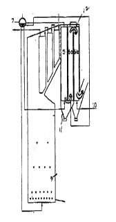
5 FIGURE 1 is a schematic side view of an exemplary prior art recovery boiler
with economizers;
FIGURE 2 is a schematic side view of an exemplary apparatus according to
the present invention in which a conventional recovery boiler is
provided with a vertical flow boiler bank, i.e. in which the flue
gases flow through a boiler bank vertically, downwardly from
above;
FIGURE 3 is a schematic side view of an exemplary apparatus according to
the present invention in which a conventional double-drum boiler
is provided with two economizers; and
15 FIGURE 4 is a schematic side view of an exemplary apparatus according to
the present invention in which a double drum boiler is provided
with three economizers.
CONVENTIONAL PRIOR ART RECOVERY BOILER
A conventional recovery boiler for combusting waste liquor (e.g. black
20 liquor) typically comprises the following main components that are
schematically illustrated in FIGURE 1:
- A lower part 1 of the furnace, in which burning of the waste liquor is
primarily performed.
- A middle part 2 of the furnace, in which final combustion of the
25 gaseous combustible substances primarily occurs.
- An upper part 3 of the furnace.
- A superheater zone 4, in which the temperature of the saturated
vapour coming from a steam drum is raised
(the vapour being thus superheated). In the superheater zone 4, or upstream
30 thereof, there is usually a screen boiler surface or screen tube system, which
also functions as a water boiler.
- A boiler bank or steam-generating section 5, in which water at a
saturated temperature is boiled into vapour.
~17105~
~_ --4--
- Economizers 6a, 6b, in which the feed water flowing in the heat
exchange elements is pre-heated prior to the water being passed into a drum
7, the boiler bank 5 and the superheating zone 4.
- A drum (i.e. steam drum) 7, having water in the lower part thereof and
saturated vapour in the upper part thereof. Some boilers are provided with two
drums: a vapour drum (upper drum) and a water drum (lower drum), between
which a heat exchanger (i.e. boiler bank tubes) is located.
- Other standard boiler parts and equipment, e.g. a combustion air
system, a flue gas system, a feeding system for black liquor to be burned, a
treatment system for melt and liquor, feed water pumps, etc.
In a conventional recovery boiler for waste liquor schematically
illustrated in FIGURE 1, in which there is a vertical flow boiler bank 5, the flue
gases flow vertically downwardly from above. Adjacent to the boiler bank there
is a passage 8, in which flue gases that have passed through the boiler bank
5 flow upwardly. Typically, the passage 8 is not provided with heat
exchangers. Adjacent to the passage 8 there is a first economizer (a
"hotter economizer") 6a. In hotter economizer 6a the flue gases flow
downwardly from above, transferring heat to the feed water flowing in the
heat exchange elements thereof. Correspondingly, adjacent to the hotter
economizer 6a there is a second flue gas passage 9, in which the flue gases
from the lower part of the economizer 6a flow upwardly. The passage 9 is
also, as conventional, an empty passage, containing neither heat exchange
elements for heat recovery nor water pre-heaters. Adjacent to the flue gas
passage 9 there is a second economizer (a "colder economizer") 6b, in which
the flue gases flow downwardly from above, heating the feed water flowing
in heat exchange elements thereof.
In addition to the boiler bank 5, two economizers 6a,
6b and the passages 8, 9 between them, the boiler may be provided with other
corresponding flue gas passages and economizers.
Heat exchangers for heat recovery, i.e. the boiler bank 5 and the
economizers 6a, 6b, are usually constructed in such a way that the flue gas
does not flow upwardly from below, but in general flows merely downwardly
from above.
2171058
-5-
ln some arrangements, in particular in older recovery boilers, the flue
gases have been directed by baffles to partly or totally deviate from a verticalflow path, but in these instances the flow of the flue gases is also, in general,
substantially downwardly from above. In some recovery boilers the boiler bank
5 is constructed in such a way that the flue gases flow substantially horizontally.
In single-drum boilers provided with a horizontal flow boiler bank, the heat
exchange elements of the boiler bank are typically positioned in such a way
that the water to be boiled will flow substantially upwardly from below. The
boiler bank is called a "horizontal boiler bank" since the flue gases flow
10 substantially horizontally. Double-drum boilers are typically provided with an
upper drum and a lower drum, the boiler bank tubes being positioned between
them in such a way that the water to be boiled will flow in the tubes
substantially upwardly from below, the flue gases flowing substantially
horizontally. In this case the term "cross- flow" is used to describe the flue gas
15 and water flows, and the term "cross-flow boiler bank" for the boiler bank.
In economizers the direction of flow of the water is usually reverse to
the direction of flow of the flue gases in order to achieve desirable heat
recovery. An economizer may also be of a cross-flow type, for example
constructed in such a way that the water in the heat exchange elements of the
20 economizer will flow substantially horizontally.
The flue gases are, as known, made to flow downwardly from above in
the boiler bank and economizers. The ash passing along with the flue gases
tends to foul heat exchange surfaces. Ash particles stick to the heat exchange
surfaces, and the ash deposit gradually grows thicker, which lessens heat
25 exchange efficiency. If a great deal of ash accumulates on the surfaces, the
resistance to the flow of the flue gas may grow disturbingly great.
Heat exchange surfaces are cleaned by means of steam sootblowers
through which steam is from time to time blown to the heat exchange
surfaces. The ash accumulated on the surfaces is loosened and passes along
30 with the flue gases into ash hoppers at the lower part of the heat exchange
surface.
During the past few years, the dry solids content of the waste liquor to
be burnt has been successfully raised to a level much higher than previously
practical. The dry solids content of the waste liquor to be burnt was previously
2 ~ 5 8
'._
between about 58-68%, while in modern recovery boilers it is as a rule more
than 68%, usually between about 70-80%, and in some plants even more than
about 80% (e.g. about 80-90%). When burning waste liquor having a high dry
solids content, the sulphur dioxide concentration has dropped to nearly zero,
whereas in boilers burning liquor having a low dry solids content, it has been
significantly higher, often hundreds of ppm.
It is well known that a recovery boiler is the most expensive individual
piece of equipment investment for a chemical pulp mill. Therefore, boilers have
to be subjected to continuous development so that they can be constructed at
lower cost. Also, the structure of a boiler has to be developed in such a way
that those properties (e.g. the raised dry solids content) of strong black liquor
that have changed from what they used to be, are taken into account.
The Invention
The invention provides a boiler construction that is simpler than known
constructions. The construction of the invention has characteristics that make
it suitable for burning black liquor with the dry solids content of over 68%,
even over about 80%.
The invention also provides an economizer system for pre-heating the
feed water in the boiler that requires less space than previous pre-heating
systems.
It is a characteristic of the apparatus according to the present invention
that economizers for feed water are provided that are connected in series and
positioned substantially adjacent to each other in such a way that there are no
separate flue gas passages between them.
It is a characteristic of the method according to the present invention
that the flue gases are made to flow through economizers connected in series
and positioned substantially adjacent to each other, the direction of gas flow
being in the reverse directions in two economizers positioned one immediately
after the other in the path of gas movement.
Properties of the ash that passes along with the flue gases when burning
waste liquor with high dry solids content are exploited according to the
invention. Ash will no longer stick to the heat exchange surfaces as easily as
previously. Also, new processes which improve the burning properties of waste
~'
,~
~f
~ ~ 7 ~ 0 5 ~
-7-
liquor have been developed, so that the tendency of the ash to stick to the
heat exchange surfaces has been successfully diminished. One such process
is the Liquor Heat Treatment (LHT) process. Using the LHT process it is
possible to reduce the viscosity of the liquor and also to remove some
compounds, e.g. sulphuric compounds, as disclosed in US patents 4929307
and 5277759. The designation "economizer" as used in the present
specification and claims is only to denote heat exchange units used for heat
transfer, and the scope of the invention is not be limited by the use of this
term to any particular design of a gas-to-liquid heat exchanger. An
"economizer" is any heat exchanger (or plurality or grouping of heat
exchangers) comprising heat exchange elements in which feed water to be
heated flows inside the elements. Between the heat exchange elements of an
economizer there is space for flowing flue gas. As the flue gas flows past the
heat exchange elements, heat is transferred into the feed water flowing inside
1 5 the elements.
A "boiler bank" as that term is used herein, is also formed by heat
exchange elements in which water to be boiled, or a mixture of water and
steam, flows inside the elements and into which heat is transferred from the
flue gas flowing past the elements.
According to the invention, the economizers, or the boiler bank and the
economizers, are positioned substantially adjacent to each other. "Substantiallyadjacent to each other" means that each subsequent economizer (being the
latter in the path of movement of the flue gas, i.e. a colder economizer) is
positioned immediately adjacent to the preceding economizer (i.e. a hotter
economizer) in such a way that the upper end of the heat exchange elements
of the latter economizer is at substantially the same level as the upper end of
the heat exchange elements of the preceding economizer or boiler bank, or at
least being no lower or higher relative to the upper end of the heat exchange
elements of the preceding economizer or boiler bank than less than about one
third (1/3) the total length of the preceding economizer or boiler bank.
According to one aspect of the present invention a recovery boiler is
provided comprising the following components: A furnace for burning waste
liquor to produce flue gases, and including an upper portion through which flue
gases flow. At least first and second economizers for preheating feed water
,~.
.~
21710~8
-- -8-
flowing therethrough by bringing the feed water into heat exchange
relationship with the flue gases, the economizers located downstream of the
upper portion of the furnace and positioned in heat exchange relationship with
the flue gases. And, wherein the economizers are positioned substantially
adjacent each other and connected in such a way that flue gas leaving the first
economizer passes substantially directly (i.e. without going through a
conventional accessory passage) into the second economizer.
Each of the economizers has an inlet and an outlet for flue gases.
Preferably the first economizer outlet and second economizer inlet are
connected together by a reverse turn so that flue gas flowing through the first
economizer in a first direction is directed to flow through the second
economizer in a second direction substantially opposite the first direction.
There also may be a third (or more) economizer having an inlet and an outlet,
with the third economizer inlet connected by a reverse turn to the second
economizer outlet so that the flue gas leaving the second economizer passes
substantially directly into the third economizer inlet. The first economizer
outlet is at substantially the same level as the second economizer inlet, or at
least the first economizer outlet is vertically spaced less than about one-thirdthe length of the first economizer from the second economizer inlet. The same
relationship holds true between the second and third economizers.
The first economizer inlet may be vertically below the first economizer
outlet so that flue gases flow substantially upwardly through the first
economizer, or positioned vice-versa (that is so that the flue gases flow
substantially downwardly through the first economizer). A boiler bank is
typically provided connected between the superheater of the recovery boiler
and the first economizer although the first economizer may be disposed
immediately adjacent the superheater zone adjacent the upper portion of the
furnace, with no intervening boiler bank (in this situation the flue gas typically
flows substantially downwardly through the first economizer).
According to another aspect of the present invention a method of
operating a recovery boiler having a furnace with an upper portion in which fluegases flow, and at least first and second economizers, is provided.
2171058
g
The method comprises the following steps: (a) Burning cellulose pulp
production waste liquor (typically black liquor) in the recovery boiler furnace so
that flue gases are generated and flow upwardly to the upper portion of the
furnace; (b) causing the flue gases to flow from the upper portion of the
5 furnace into the first economizer, cooling the flue gases in the first economizer,
and causing the cooled gases to exit the first economizer; and (c) passing flue
gases from the first economizer substantially directly to the second
economizer, without causing it to flow through an accessory passage, cooling
the flue gases in the second economizer, and causing the cooled gases to exit
1 0 the second economizer.
Step (b) is typically practiced to cause the flue gas to flow in a first
substantially vertical direction and step (c) to cause the flue gas to flow in asecond substantially vertical direction substantially opposite the first direction.
The first direction may be substantially upwardly and the second direction
1 5 substantially downwardly, or vice-versa.
Step (a) is typically practiced by introducing black liquor having a
consistency of over about 70% into the furnace and burning the black liquor.
Step (a) is also typically further practiced by introducing black liquor having a
dry solids concentration of at most about 3% potassium, and at most about
20 1 % chlorine.
There typically is the further step (d), before step (b), of passing the flue
gases through a boiler bank and cooling the flue gases in the boiler bank. A
third economizer (or more) may also be utilized in which case there is the
further step (e) of passing flue gases from the second economizer substantially
25 directly to the third economizer, without causing it to flow through an
accessory passage, cooling the flue gases in the third economizer, and causing
the cooled gases to exit the third economizer.
Water circulates in the economizers, and there typically is the further
step of causing the water circulating in each of the economizers to flow in a
30 direction substantially opposite the direction of flow of flue gases through each
respective economizer.
It is the primary object of the present invention to provide an
advantageous method and apparatus for transfer- ring heat from flue gases to
circulating water in recovery boiler economizers or the like. This and other
217105~
-- -10-
objects of the invention will become clear from an inspection of the detailed
description of the invention and from the appended claims.
DETAILED DESCRIPTION OF THE INVENTION
FIGURE 2 illustrates a recovery boiler in which a hotter vertical economizer
5 6a in accordance with the invention is positioned adjacent to a vertical flow
boiler bank 5 in such a way that after coming out of the boiler bank 5, the fluegases may flow substantially directly to the hotter economizer 6a, in which
they preferably flow upwardly from below. At the turning point (reverse turn)
of the flue gases in the lower part of the boiler bank 5 there is a conventional10 ash hopper 1 1, into which part of the fly ash accumulates for further use. The
feed water to be heated preferably flows in the economizer 6a in a direction
counter-current to the flue gas flow, however according to the present
invention the feed water may alternatively flow concurrently to the flow
direction of the flue gases. Adjacent to the hotter economizer 6a, a colder
15 vertical economizer 6b is positioned in such a way that between the
economizers 6a 6b, there is no separate empty flue gas passage (such as the
passage 8 in FIGURE 1).
After flowing through the hotter economizer 6a to the upper part thereof,
the flue gases flow substantially directly to the next (colder) economizer 6b,
20 in which they preferably flow downwardly from above as indicated by arrow
12 in FIGURE 2. In the colder economizer 6b the feed water to be heated
preferably flows through a tube 10 counter-currently to the flow direction of
the flue gases.
FIGURE 3 schematically illustrates how, in accordance with an
25 alternative construction according to the invention, a boiler bank 15 is
constructed in such a way that the flue gases flow substantially horizontally
there- through. This is effected, for example, for boilers provided with two
drums and a boiler bank tube system between the drums. Also in single-drum
boilers, a boiler bank is sometimes used in which the flue gases flow
30 horizontally. In such a construction the flue gases, having passed through the
boiler bank 15, flow (as is conventional) directly to the upper part of a hottereconomizer 1 6a. In economizer 16a the flue gases flow downwardly from
above. The present invention can be utilized here in such a way that after the
2171058
'-- - 1 1 -
hotter economizer 16a, the flue gases flow substantially directly to a colder
economizer 16b, in which they flow upwardly from below, as indicated by
arrow 17 in FIGURE 3. At the turning point of the flue gases below the hotter
economizer 1 6a there is a conventional ash hopper 18. If the boiler is providedwith a third economizer (such as 26c, as is schematically illustrated in FIGURE
4), the flue gases flow downwardly from above therein (as indicated by arrow
27 in FIGURE 4), so that again there are no empty passages for the flow of
flue gases between the various economizers.
According to the invention the construction details of the heat exchange
surfaces of a recovery boiler for waste liquor, and the number thereof, may be
different from what is described above. For example, there may be more than
two economizers, such as three (FIGURE 4), or even more.
The present invention is also applicable to boilers with no separate boiler
bank after the superheating zone (4). In this case, the flue gases flow directlyto a hotter economizer after the superheating zone (4), and therefrom further
to the following economizers.
The present invention is especially applicable to those instances where
the dry solids content of the waste liquor to be burnt is over about 70%,
typically between about 70-90%, or where the waste liquor does not contain
significant amounts of components having a tendency to foul heat exchange
surfaces. The invention is especially suitable for such cases where the dry
solids of the waste liquor contain at most about three per cent potassium and
at most about one per cent chlorine; however, the applicability of the inventionis not necessarily limited to these properties of waste liquor.
Advantages achieved by the invention from the elimination of empty
flowing passages for flue gas are a significant reduction in the total cost of the
recovery boiler, and a reduction in the volume of space taken up thereby.
While the invention has been described in connection with what is
presently considered to be the most practical and preferred embodiment, it is
to be understood that the invention is not to be limited to the disclosed
embodiment, but on the contrary, is intended to cover various modifications
and equivalent arrangements included within the spirit and scope of the
appended claims.