Note: Descriptions are shown in the official language in which they were submitted.
wo 95/08211 2 1 7 1 0 8 q PCT/US94/10454
SUPERCONDUCTING ROTOR
BACKGROUND OF THE INVENTION
This invention relates to the superconducting rotor of an electric
5 motor and more particularly to cooling such a rotor to m~int~in its field coils
in the superconducting state.
Superconducting rotating machines such as motors and generators
must be cooled such that the field structures of their rotors are in the
supercon(l--ctin~ state. The conventional approach to cooling rotor field
10 coils is to immerse the rotor in a cryogenic liquid. For example, a rotor
employing conventional, low temperature superconducting materials might
be irnmersed in liquid helium. Similarly, rotors employing field coils made
of high temperature supercon~l--cting materials would be immersed in liquid
nitrogen. In either case, heat generated by or contlncte-l into the rotor is
15 absorbed by the cryogenic liquid which undergoes a phase change to the
gaseous state. Consequently, the cryogenic liquid must be replenished on a
contin--in~ basis. This replenishment is accomplished through a L,~lLs~r line
that feeds the cryogenic liquid into the rotating machine along the axis of the
rotor. A rotating, cryogenic leak-tight seal is required in the transfer line.
20 Rotating seals require surfaces which slide on one another in extremely closecontact to prevent leakages. Since the surfaces rub, friction will wear them
away and eventually create a gap. At room temperature, elastomers are
used to elimin~t~ this problem but there are no known materials which have
suitable elastomeric properties at cryogenic temperatures. Consequently,
25 rotating cryogenic leak-tight seals are available only as custom products and require frequent maintenance and parts replacement.
The dynamic stability of rotating systems employing a free liquid is
difficult to m~int~in Rotation can cause wave action resulting in a
mech~nic~l imbalance in the rotor. Further, because the liquid is in a
30 rotating system, the rotational acceleration ~s~uli~es the cryogenic fluid
with the maximum pressure at the periphery of the machine. This
WO 9S/08211 2 1 7 1 0 8 9 PCT/US9~11045~ --
pressurization causes the boiling point of the cryogenic liquid to be elevated.
At atmospheric pressure, liquid nitrogen boils at 77K. However, for a rotor
36 centimeters in diameter rotating at 3600 rpm, the boiling point is
approximately 97K, which is very close to or higher than the transition
5 temperature of some ceramic oxide high temperature superconductors.
Moreover, for such high temperature superconductors it is known that their
performance is greatly enh~nce(l at temperatures below the transition
temperature. In the bismuth~ lLiulll-calcium-copper oxide (BSCCO) 2223
system, for example, a three times higher magnetic field can be generated
10 by cooling the superconductor to 50K as compared to the 77K of liquid
nitrogen at atrnospheric pressure.
Another approach for achieving cryogenic temperatures, though
heretofore not in a rotating ellvi~olllllent, is the cryogenic refrigerator or
cryocooler. Cryocoolers are mechanical devices operating in one of several
15 thermodynamic cycles such as the Gifford-McMahon cycle and the Stirling
cycle. Cryocoolers have found application, for example, in cooling the
stationary magnets in magnetic resonance im~gin~ systems. See, for
example, M.T.G van der Laan et al., "A 12k superconducting Magnet
System, Cooled via Thermal Conduction by Means of Cryocoolers",
20 Advances in Cryogenic Engineering, Volume 37, Part B, (Proceedings of the
1991 Cryogenic Engineering Conference) edited by R. W. Fast, page 1517
and G. WaLker et al., " Cryocoolers for the New High-Tem~erature
Superconductors," Journal of Superconductivity, Vol. 1 No.2, 1988. It is
well known to those skilled in the art that good cryocooler perform~n~e
25 depends on a design uptimi7P~l for the actual conditions the cryocooler
operates under. Known cryocoolers usually do not have a rotational axis of
symmetry and are not otherwise adapted for operation in a rotating
environment and therefore are not suitable for such application.
2171089
WO 95/08211 PCT/US94/ln454
SIJMMARY OF THI~ INVENTION
The superconducting rotor according to one aspect of the invention
includes a rotor with at least one field coil made of a superconductor
material having a superconducting transition temperature. A cryocooler
system including a cold head is mounted on the rotor for rotation with the
rotor. The cold head is mounted on the rotor in a heat transfer relation with
the coil so as to cool the coil to a temperature below its transition
temperature. The cryocooler may be a single stage or a multi-stage device.
In a preferred embodiment, the field coil and the cold head are both in
intim:~te thermal contact with structure having a high coefficient of thermal
conductivity. In another embodiment, at least one heat pipe is disposed
between the coil and the cold head for conducting heat away from the coil.
In these embodiments a non-rotating compressor is provided for delivering a
high pressure working fluid nominally at ambient temperature to the cold
head and for receiving lower pressure working fluid from the cold head.
The compressor and cold head are in fluid Collllllul~iCatiOn through a rotary
joint which is at room temperature. It is ~ler~ d that the high pressure
working fluid be conveyed in a first line disposed within a second line which
also conveys the lower pressure working fluid.
In yet another aspect of the invention, the compressor along with the
cold head is mounted for rotation with the rotor. In this embodiment, the
compressor receives electrical power through electrically con-lncting
slip-rings.
In all of these embodiments it is preferred that the cryocooler system
have a longihl~lin~l axis coincident with the axis of rotation of the rotor to
which it is attached. It is also preferred that the lon~ihl-lin~l axis of the
cryocooler be an axis having rotational symmetry to assure acceptable
rotational perform~nre. When the dominant cooling mode is heat
conduction through structure supporting the field coil and the cryocooler, the
structure may include a plurality of axially spaced apart ~nmll~r members
WO 95/08211 2 1 7 1 0 8 q PCT/US94/1045~ --
connected by axially extending lon~ in~l members having high thermal
conductivity properties.
The cryocooler forming a part of the present invention includes a
reciprocating piston/regenerator which may be driven by a linear motor
5 assembly or a voice coil system and which includes a piston/regenerator
adapted to allow passage of a working fluid at a mass flow rate which is
uniform over the cross-section of the piston/regenerator during operation of
the system. The cryocooler may operate on any a~lu~liate thermodynamic
cycle such as the Gifford-McMahon cycle and the Stirling cycle. Suitable
10 working fluids are helium, neon, nitrogen, hydrogen and oxygen.
The superconductor material forming the field coil may be either
conventional, low temperature superconductors such as niobium-tin having a
transition lenl~eldture below 35K or a high temperature superconductor
having a transition temperature above 35K. Suitable high temperature
15 superconductors for the field coils are members of the bismuth-~llollliulll-
calcium-copper oxide family, the yttrium-barium-copper oxide system,
mercury based materials and th~ lm-based high temperature superconductor
materials. The cryocooler characteristics are selected to provide a rotor
temperature below the transition temperature of the superconductor and,
20 preferably, well below the transition temperature of the superconductor.
Because the present invention employs a cryocooler mounted for
rotation with the rotor, there is no pool of liquid to disturb the dynamic
balance of the system. Further, by using heat pipes or highly thermally
conductive material t~ elature gradients within the field coil are reduced.
25 The present invention also elimin~tPs a crvogenic rotary joint. Importantly,
the cryocooler can cool the field coil well below the transition temperature
of the superconductor.
WO 9S/08211 2 1 7 1 0 8 9 PCT/USg4/10454
BRIEF DESCRIPIION OF THE DRAWING
Fig. 1 is a cross-sectional view of the supercon~ ctin~ rotor of the
present invention.
Fig. 2 is a cross-sectional view of an embodiment of the
5 superconducting rotor according to the present invention including a
compressor which rotates with the rotor.
Fig. 3 is a schematic cross-sectional view of a cryocooler.
Fig. 4 is a cross-sectional view of a two-stage rotatable cryocooler.
Fig. 5 is a schematic, cross-sectional view of a single stage rotatable
10 cryocooler.
Fig. 6 is a cross-sectional view of a heat pipe used in the invention.
Fig. 7 is a perspective view of a piston/regenerator in accordance
with a preferred embodiment of the invention.
DESCRl[PIION OF THE PREFERRED EMBODIMENT
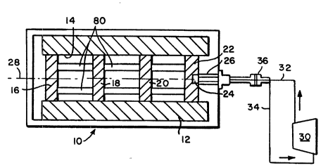
With reference first to Fig. 1, a supercontl~lctinp~ rotor 10 includes a
field coil winding 12 supported on a mandrel 14. The field coil winding 12
is preferably made of a high temperature supercon(lllcting wire material such
as material available from the American Superconductor Corporation of
20 Westboro, Massachusetts. Other suppliers of suitable supercon~lçtin~
materials are IGC of Guilderland, New York and Sumitomo Electric of
Japan. A~lo~liate superconductors may be selected from the known classes
of high temperature superconducting materials. The field coil winding 12
may also be made from conventional, low temperature superconductors.
25 The embodiment of Fig. 1 includes a plurality of spaced apart, ~nmll~r
members 16, 18, 20 and 22 which are in close mech~nic~l and thermal
contact with the coil 12 and the mandrel 14 on which the field coil winding
12 is wound. Both the ~nmll~r members 16-22 and the mandrel 14 are made
of high thermal conductivity material such as copper. The mandrel 14 and
30 ~nmll~r members 16-22 also provide mechanical rigidity to the entire coil
2171089
WO 95/08211 PCTtUS9411045
structure which is subjected in operation both to substantial centrifugal and
magnetic forces.
A cold head end 24 of a cryocooler assembly 26 is disposed within a
recess in the angular member 22. It is preferred that an axis of symmetry of
the cryocooler 26 be coincident with the axis of rotation 28 of the rotor 10.
As will be described in more detail below, the cryocooler 26 receives a high
pressure working fluid from a c~ essor 30 through a line 32. Lower
~les~ule working fluid is returned to the compressor 30 through a line 34.
The lines 32 and 34 are in fluid collllllunication with the cryocooler 26
through a rotary coupling or junction 36.
During operation, the cold head 24 will extract heat both from the
~nmll~r member 22 and, because of the highly thermally contlllctin~ nature
of the interconnecting structure, from the field coil winding 12. In this
embodiment, the colll~ressor 30 does not rotate with the rotor 10.
Fig. 2 shows an embodiment of the invention in which both the
cryocooler 26 and the compressor 30 are mounted for rotation with the rotor
10. An electrically conducting slip-ring assembly 38 allows electricity to be
transported to the compressor 30 from a non-rotating source of electrical
energy 40. The embodiment of Figure 2 obviates the fluid rotary joint 36 of
the embodiment of Fig. 1.
As is well understood, cryocoolers such as the cyrocooler 26 is a
refrigeration device in which cooling is accomplished by rapid expansion of
compressed working fluid and may be designed to operate according to a
number of thermodynamic cycles such as the Gifford-McMahon cycle, the
Stirling cycle or a variation on the Stirling cycle known as the pulse-tube
cycle. Cryocoolers operating on any of these cycles or on any other
thermodynamic principles that will provide the desired low critical
temperatures may be used in practicing the present invention.
The cryocooler 26 is shown schem~til~lly in Fig. 3. A high pressure
working fluid such as helium or neon is supplied via the line 32 to the
WO 95/08211 2 1 7 1 0 8 9 PCTIUS94/10454
interior of the cryocooler 26 through the rotary joint 36. A
piston/regenerator element 42 reciprocates within the cryocooler 26. The
piston/regenerator is caused to reciprocate by a linear motor assembly 44.
Lower pressure working fluid returns to the colllpressor 30 via the line 34.
As those skilled in the art will appreciate, upon reciprocation of the
piston/regenerator 42, the cold head 24 is cooled and will remove heat from
its ~ llltlings. Cryocoolers which are commercially available from a
number of m~nllf~cturers including Edwards Vacuum of Wilmington, MA,
CTI Cryogenics of Mansfield, MA, and Cryomac Corporation, and Carrier
Corporation, both of Syracuse, New York, may be modified to operate in
accordance with the invention by, for example, modifying the drive
configuration as described in relation to either FIGS 3 and 4 or FIG 5 and
additionally modifying the fluid piston/regenerator system as described in
relation to FIG 7 below.
With reference now to Fig. 4, the cryocooler 26 is shown in more
detail. This cryocooler 26 is a two stage cryocooler including a first stage
expander portion 50 and a second stage expander portion 52. Annular seals
54 and 56 form a sealing relationship with the piston/regenerator 42. The
piston/regenerator 42 is affixed to a moving coil assembly 58 by means of a
connector 60. A permanent magnet structure 62 includes a groove 64 into
which the moving coil 58 may move without interference. A high pressure
working gas (not shown) is introduced into the cryocooler 26 through a line
70 and lower pressure return working gas flows through a line 72. Flow of
the high pressure gas is controlled by a valve 74 and flow of the low
pressure working gas is controlled by a valve 76.
The cryocooler of Fig. 4 has two stages of cooling at dir~elenl
temperatures. The first stage employing the first stage expander 50 portion
operates at a higher temperature and rejects heat to the ambient temperature
environment and the second stage employing the second stage expander 52
operates in the temperature range of 20-80K rejecting heat to the first stage
2171089
WO 95/08211 , PCT/US9~1/10454
portion. Continuous cooling is accomplished by the expansion of the
working gas in the two expanders 50 and 52 through the oscillatory motion
of the piston/regenerator 42 and the appropriate opening and closing of the
valves 74 and 76 which will be discussed below.
The oscillatory motion of the piston/regenerator 42 is accomplished in
this embodiment by the voice coil assembly illustrated. The moving coil 58
is solenoidal in geometry. The moving coil interacts with the permanent
m~gnet structure 62 which is made of any ferromagnetic material having the
ability to remain magnetized. Suitable materials are iron, SmCo, NdFe, B,
etc. The permanent m~gn~t structure 62 is m~gnPti7e~1 in such a way as to
have a radially oriented permanent field in the anular groove 64. The
moving coil 58 is excited by an alternating current through sliprings 78. A
force proportional to the product of the current through the moving coil 58
and the magnetic field in the anular groove is imposed on the moving coil 58
resl-lting in oscillatory motion of the piston/regenerator 42.
The cryocooler assembly 26 is connected to an external source of
compressed gas (not shown) via the pair of concentric pipes 70 and 72.
This concentric pipe arrangement is connected to the pair of electrically
~t~l~tP-l valves 74 and 76 to control the flow of gas into and out of the
cryocooler 26. The timing sequence for the valves 74 and 76 will now be
described.
With the piston/regenerator 42 in the leftmost position, high pressure
gas valve 74 is opened. Gas flows into the cold head through the
piston/regenerator 42, cooling during its passage, and pressurizes the
expander portions. The valve 74 is then closed and the piston/regenerator
42 moves to the right exp~n~ing.the gas in both expander stages. This
expansion causes the gas to cool further. The valve 76 is then opened as the
piston/regenerator 42 moves to the left. The gas absorbs heat from the
superconducting rotor to which it is thermally conn~cte-l. The gas flows
through the piston/regenerator 42 and then back to the compressor (not
~ WO95/08211 2 1 7 1 0 8 9 PCTIUSg4/10454
shown in Fig. 4). The valve 76 is then closed with the cycle repeating
thereafter. The entire assembly 26 is built having a common axis of
symmetry which enables its operation in both a static and a rotating
environment.
The piston/regenerator has a set of axially oriented passages adapted
to allow passage of the working fluid at a mass flow rate which is
subst~nti~lly uniform over the corss-section of the piston/regenerator during
operation of the system. In the preferred embodiment, the sizes and spacing
of these passages are such that the total cross sectional area of the openings
in a unit area of the piston/regenerator varies ina subst~nti~lly inverse
relation with the radial position, and most preferably, subst~nti~lly inversely
with the fourth power of the radial position, of the passage measured from
the axis of symmetry of the piston/regenerator. For example, as shown in
FIG 7, the piston/regenerator 42, is composed of, for example, a stack of
high thermal conductivity perforated or porous disks lOO(A), (B),
separated by low thermal conductivity perforated or porous separators
102(A),(B),... For perforated disks and separators, the perforations should
be subt~nti~lly aligned in an axial direction to provide a path for continuous
fluid flow through the piston/regenerator. The piston/regenerator 42
20 provides a composite structure which has a high radial thermal conductivity
but a low axial thermal conductivity. The disks 100 may be made of any
materials which have high thermal conductivity and high heat capacity, such
as copper, silver or other highly conductive metals, ~ min~, magnesia or
other thermally conductive ceramics, and phase transition materials such as
25 ferromagnetic materials with Curie te~ ,el~tures in the operating temperature range of the piston/regenerator. The separators 102 may be made from
plastics such as perforated Mylar~ or Teflon~, wood, paper, or any other
WO 95/08211 ~ 1 7 1 0 8 ~ PCTIUS9~/10454
low conducting permeable material. The spacing and size of the openings
92, 94(A)-(C), 96(A)-(F), and 98(A)-(H) in each disk is varied so that the
total flow area at each radius, such as the area 108 encompassing opendings
96(A)-(F) at radius 106, decreases subst~nti~lly inversely as the fourth
5 power of that radius measured from the axis of symmetry 104 of the
piston/regenerator. Thus, during operation of the piston/regenerator 42 in a
rotating environment, the mass flow rate of the fluid is subst~nti~lly ul~iflo
over the cross section of the piston/regenerator.
Fig. 5 is an embodiment of a cryocooler having just a single stage.
10 This single stage device operates similarly to the two stage embodiment
described above with respect to Fig. 4.
With reference again to Fig. 1, the spaced apart ~nmll~r members 16-
22 may be interconnected by a plurality of heat pipes 80. A cross-sectional
view of a representative heat pipe 80 is shown in Fig. 6. The heat pipe 80
15 includes a highly thermally conductive tube 52 which is sealed at its ends.
Suitable materials for the tube 82 are high strength cooper or ~ mimlm
alloys. The inner wall of the tube 84 is lined with a porous wick material
84 and the tube also includes a cryogenic working fluid (not shown) such as
helium, neon or nitrogen. In a preferred embodiment, the wick material 84
20 is sintered ceramic. Other wick materials such as fine woven metallic mesh,
fibrous cloths or sintered metal powders may also be used. The quantity of
cryogenic working fluid in the heat pipe 80 is selected such that given the
total internal volume of the heat pipe 80, approximately 5-25 % of the
cryogenic working fluid will be condensed and in liquid form at the desired
25 operating temperature.
In operation, working fluid within the heat pipe 80 condenses at the
end adjacent to the cold head 24. The condensed working fluid travels by
capillary action along the wick 84 absorbing heat as it travels. It undergoes
a phase transition to the vapor state and travels through the center of the
30 heat pipe 80 back to the cold end adjacent to the cold head 24. Because the
~ WO95/08211 2 1 7 1 089 PCTIUSg4/10454
heat pipes 80 are an intim~te thermal contact with the ~nmll~r members 16-
22, heat in the field coil win-ling.c 12 will be removed so that the win-lingc
12 are m~int~ined below the critical temperature of the superconductor
material from which they are made.
With reference again to Figs. 3, 4 and 5 a preferred working fluid
within the cryocooler 26 is neon. Although lower temperatures (e.g., about
20K) can be obtained with helium as the working fluid, the heavier neon gas
makes operation of the compressor 30 and of the piston/regenerator 42 more
efficient. Further, the larger atomic volume of neon reduces leakage at the
transfer coupling 36. Nitrogen is another suitable working fluid for the
cryocooler 26. Neon is also the preferred working fluid within the heat pipe
80 for wo~ g temperatures in the 30-40K range.
In other embodiments, highly thermally conductive rods (e.g.,
copper) may be substituted for the heat pipes 80. Such rods or the heat
pipes 80, of course, may be embedded directly within the field coil win~lingc
12, if necessary to improve heat transfer.
What is claimed is: