Note: Descriptions are shown in the official language in which they were submitted.
4~~ ~1'~I13
~TFT.D OF THE INVENTION
The present invention relates to mounting of
currency validators and accumulators in vending machines,
and in particular is directed to a mounting arrangement for
a currency validator to allow simplified securement of
validator in vending machines in a space efficient manner.
~A~'KGROL1ND OF THE INVENTION
Vending machines have typically received coins,
however, in recent years there has been a move to have
these vending machines accept bills of various
denominations. Currency validators and accumulators
basically allow vending machines to dispense more expensive
products. Currency validator and accumulators also provide
a quality control check for the owner of the vending
machine confirming that a proper bill has been received.
For this reason, Currency validators and accumulators have
become increasingly popular.
Currency validators are typically mounted in their
own unique way to suit the particular vending machine and
it is often difficult to retrofit a vending machine with a
currency validator without extensive modification. The
present invention seeks to overcome these problems by
providing a unique support arrangement for currency
validators and accumulators which is easy to use and does
not require excessive space within the vending machine for
accommodating and servicing of the validator.
~11MMA_R_Y OF THE INVENTION
A mounting structure for a currency validator and
accumulator comprises a telescopic slide secured to a
mounting bracket having a mounting plate adapted to be
fixed to a wall. The mounting bracket supports the
telescopic slide generally perpendicular to the mounting
plate with the telescopic slide telescoping in a direction
generally perpendicular to the mounting plate. The
- 1 -
~Z'~113~
telescopic slide has a first portion directly secured to
the mounting bracket and a validator mounting portion
supported by said first portion allowing telescopic
movement between a retracted position defining the normal
in-use position of a validator secured to the validator
mounting portion and a service position where the
telescopic slide is extended and provides improved access
for servicing of a supported validator.
According to an aspect of the invention, the
telescopic slide includes an intermediate portion which is
supported by the first portion and is slidable therewith,
with the intermediate portion supporting the validator
mounting portion such that a three-stage telescopic slide
is defined.
According a further aspect of the invention, the
first portion of the telescopic slide is adjustably secured
to the mounting bracket to accommodate different spacings
of the first portion from the mounting bracket which allows
for accommodation of different depths of vending machines
in which the mounting structure is intended to be secured.
According to a further aspect of the invention, the
validator mounting portion includes a pivot arrangement
adapted to allow securement of a validator in a use
position overlapping with the mounting portion and movable
to a service position generally perpendicular to the
mounting portion.
According to yet a further aspect of the invention,
the pivot arrangement includes a counterbalance mechanism
for controlling movement of a secured validator from the
service position to the in-use position.
According to a further aspect of the invention, the
telescopic slide defines two stop positions, with one stop
position defining the in-use position with the telescopic
slide contracted and the other stop position defining the
service position with the telescopic slide extended.
According to yet a further aspect of the invention,
the mounting bracket overlaps to a significant extent with
- 2 -
2171~3~
the first portion to directly support at least 50~ of the
first portion.
According to yet a further aspect of the invention,
the mounting bracket is fabricated from a single piece of
metal and is generally 'L' shaped.
According to yet a further aspect of the invention,
the 'L' shaped mounting bracket includes two side flange
arrangements located to opposite sides of the 'L' shape,
which side flanges are secured to the mounting plate and
form struts to maintain the 'L' shape.
The present invention is also directed to the
combination of a currency validator and a vending machine
where the vending machine has an interior cabinet with a
front opening door. The currency validator is secured
within the vending machine by the mounting arrangement,
which is secured to the back wall of the vending machine.
The currency validator is secured to the telescopic portion
of the mounting arrangement and the first portion of the
telescopic portion is fixed relative to the mounting
arrangement such that a portion of the currency validator
extends through a port in the front door of the vending
machine. The currency validator with the telescopic slide
fully retracted defines an in-use position with a portion
of the currency validator extending through the front door
of the vending machine and the currency validator is
movable to a service position generally forward of the
vending machine exposing the currency validator for
service.
According to yet a further aspect of the invention,
the mounting arrangement allows pivoting in a vertical
plane of the currency validator in the service position to
further increase the access to the currency validator.
~~tIEF DESCRIPTION OF THE DRAWINGS
Preferred embodiments of the invention are shown in
the drawings, wherein:
Figure 1 is a partial side view of the mounting
arrangement and validator secured in a vending machine;
- 3 -
CA 02171136 2002-03-04
WH-9478CA
Figure 2 is a side view of the mounting arrangement
and validator.
Figure 3 is a side view with a mounted validator in
a service position;
Figure 4 is a front view of a mounted validator;
Figure 5 is a sectional view taken along line B-B
of Figure 1;
Figure 6 is a partial sectional side view of an
alternate embodiment; and
Figure 7 is a top view of Figure 6.
DETAILED DESCRIPTION OF THE PREFERRED EMBODIMENTS
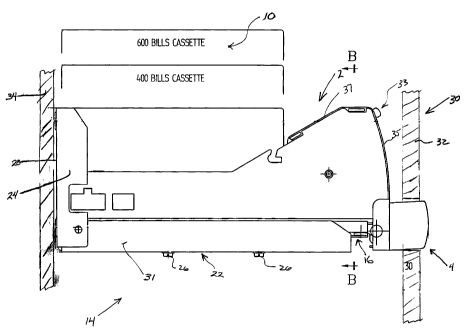
The currency validator and accumulator 2 has a nose
portion 4 which projects through the front door 32 of the
vending machine, generally shown as 30. The nose portion
includes the bill receiving slot 6, any controls 8 which
the user must access, and status indicators 9 (see Figure
5). This allows feeding of bills into the currency
validator and accumulator 2. The currency validator and
accumulator 2 includes an accumulator cassette, generally
shown as 10, in which received bills are stored. Servicing
of the currency validator includes removal of this cassette
and replacement with an empty cassette.
The mounting structure 14 is secured to the rear
wall 34 of the machine 30 (vending type machine) and
supports the currency validator and accumulator 2. The
mounting structure 14 includes a mounting plate 20 secured
to the rear wall of the vending machine and an integral
cantilevered arm 22 which projects in a cantilevered manner
from the mounting plate and in cooperation therewith forms
a generally ~L~ shaped mounting structure. Within the
mounting structure is a telescopic slide 16. This slide is
secured to the cantilevered arm 22 and the slide is also
secured to the currency validator and accumulator 2. Side
flanges 24 act as a strut between the mounting plate and
the cantilevered mounting arm 22. With the structure
shown, the mounting structure 14 is formed from a single
piece of metal bent into the 'L~ shape with the side
- 4 -
CA 02171136 2002-03-04
WH-9478CA
flanges 24 bent and riveted to underlying bent flanges 31
on the cantilevered arm 22.
Fasteners 26 serve to secure a first telescopic
portion of the telescopic slide 16 to the cantilevered arm
22. There are various ports for securing locations in the
cantilevered bracket 22 or in the first portion of the
telescopic slide to allow adjustment in the position of the
telescopic slide 16 relative to the front of the vending
machine. In this way, the location of the telescopic slide
within the mounting bracket can be adjusted to suit the
depth of the vending machine. This is particularly useful
in retrofitting vending machines and as will be more fully
described, the retrofitted currency validator and
accumulator need only have a slot to accommodate its
dimensions from the rear wall to the front wall and the
validator can slide on a telescopic slide with the front
door open to allow service. In this way, the space
occupied within the vending machine is relatively small
while still providing excellent access to the currency
validator and accumulator 2 in front of the vending machine
with the telescopic slide extended.
The validator as shown in Figure 1 has a release
lock 33 to service the guideway leading form the receiving
slot 6 to the accumulator cassette 10. Note that the front
segment 35 opens forwardly in the horizontal position of
Figure 1 (see Figure 3). Top segment 37 cooperates with
front segment 35 to form a clam shell arrangement allowing
access to the guideway. In one embodiment, the accumulator
is contained within an outer, open-ended container with the
telescopic slide located therein.
A key lock is provided on the slide to lock the
slide in a fully collapsed state with the cassette fully
received in the container and not accessible. Front
segment 35 and top segment 37 are accessible to allow
service, but not access to the cassette and money therein.
In this way, some service can be completed without
providing access to the cassette. Some jurisdictions
require two people to be present if the cassette becomes
_ 5 _
CA 02171136 2002-03-04
WH-9478CA
accessible. As shown in Figure 5, access to release lock
. 33 is at the front face, which also contains the receiving
slot 6.
Figure 2 shows three separate positions 40, 42 and
44 of the mounting structure. At position 40, the currency
validator is in a fully retracted position, i.e., the
telescopic slide is fully retracted and the position of the
telescopic slide relative to the cantilevered arm 22 is in
the fully retracted location. Position 42 again has the
telescopic slide fully retracted, however, the position of
the slide relative to the cantilevered arm 22 is in a
maximum adjustment position. Position 44 shows a fully
extended position of the telescopic slide, which is the
service position of the mounting arrangement.
Details of the slide are shown in Figure 3 where
the first portion 52 would be secured by fasteners 26 shown
in Figure 2 to the cantilevered arm 22. Figure 3 omits the
mounting arm to show details of the slide. The telescopic
slide includes an intermediate portion 54 which links the
first portion with the validator mounting portion 56. It
can also be seen how the currency validator mounting
portion 56 can be released from the intermediate member by
the release mechanism 58. During installation, the
mounting arrangement alone is secured and after securement
the validator can be secured to the telescopic slide.
Figure 4 shows further details of the slide and the
securement of the first portion to the cantilevered arm 22.
Figure 4 shows how glide blocks 60 serve to maintain the
spacings of the various portions of the telescopic slide
and allow the sliding movement therebetween.
Figure 3 shows further details of securement of the
currency validator 2 to the currency validator mounting
portion 56 of the telescopic slide. There is a pivot
connection, generally shown as 70, which allows pivoting of
the currency validator from the in-use position of Figure 1
to the service position of Figure 3. This pivot connection
includes a spring loaded counterbalance arrangement which
can be partially understood from Figure 2. In this case, a
- 6 -
478CA
~1'~i13~
torsion spring is wound about the pivot axis 71 and has a
first leg 74 secured to the telescopic slide and a second
leg 76 pressing against the validator. The spring allows
movement of the currency validator from the in-use position
of Figure 2 to the service position of Figure 3, and in so
doing, partially offsets the weight of the currency
validator. More importantly, this spring, when the
currency validator is moved from the service position to
the in-use position, provides a bias to allow controlled
movement of the validator to the service position.
Otherwise, the currency validator could merely drop under
the weight of the validator and cause damage thereto.
The nose portion 4 of the currency validator is
shown in Figure 5 and it can be seen that currency is
introduced through the access slot 6 and diagnostic
indicators 8 and 10 are provided to indicate Whether the
bill is accepted or rejected. It is only the nose portion
Which extends beyond the front door of the vending machine
and the portion generally indicated as 13 would be located
behind the front door.
From the above, it can be appreciated that the
actual space within the vending machine which the validator
requires is relative small and this space is an elongate
narrow tube-like clearing from the back wall to the front
door. This allows the exact placement of the validator to
be simplified for retrofit applications. The mounting
structure allows accommodation in different sizes of
vending machines and different spacings between the back
wall and the front door. In this way, the front door can
be retrofitted and the currency validator can be mounted in
the vending machine easily. Any adjustments necessary due
to the particular vending machine are easily accomplished
due to the adjustable relationship of the mounting bracket
and the first portion of the telescopic slide. The
telescopic slide is specifically designed to have a
substantial degree of overlap between the first portion,
the intermediate portion and the currency validator
mounting portion. In this way, the telescopic slide is
_ 7 _
~1'~1136
relatively stiff. The degree of overlap is in the range of
approximately 50~ of the length of each slide. This allows
a very positive support of the currency validator when it
is in the service position. As can be appreciated, the
currency validator is slid forward to a clear position,
i.e. a position forward of the internals of the vending
machine, and then the currency validator can be rotated in
the vertical plane to the 90° service position. In
addition, even if the currency validator is not rotated,
the bill accumulator or cassette is immediately accessible
to remove the cassette and insert a new one. It is also
possible to have different sizes of the 'L' shaped
brackets, should further adjustment of the currency
validator be necessary. It can also be appreciated that in
some cases it may be desirable to have a downwardly
mounting bracket, which again would have a cantilevered
member which would allow adjustable positioning of the
slide relative to the counter member in the manner
described. It can also be appreciated that a side mount
bracket could be used. It has been found that the rear
mount wall bracket is the easiest and in most cases the
most practical bracket for retrofitting vending machines.
The mounting system is also useful for new vending
machines, and therefore, the application is not restricted
to retrofitting of vending machines.
Vending machines are used in a very generic sense
to identify a broad range of machines which provide users
with a particular product or service based on the user
initially authorizing the machine by entering a bill in the
currency validator accumulator. Such vending machines can
include video machines, machines used in casinos for
dispensing chips or markers, food dispensing machines,
amusement machines, parking ticket issuing machines and
gaming machines, as but some examples.
An alternate embodiment of the mounting structure
is shown in Figures 6 and 7. The mounting structures,
generally shown as 114, includes a mounting plate 120 for
securement to the rear wall of a machine or cabinet and a
_ g _
478CA
mounting arm 122 which projects in a cantilevered manner
from the mounting plate and forms therewith a generally 'L'
shaped mounting structure. Attached to the mounting arm
122 is a telescopic slide arrangement, generally shown as
116.
In this embodiment, the validator is secured to the
mounting brackets 158 which are pivotally secured by pivot
160 to the third portion 156 of the slide 116. As in the
earlier embodiment, there is an intermediate or second
portion 154 and a first portion of the telescopic slide,
shown as 152. The third portion 156, as shown in Figure 7,
is shorter in length and essentially terminates at the
mounting brackets 158. The validator is secured to the
mounting brackets 158 at a position slightly in front of
the mid portion of the validator and to the lower surface
of the validator. In this way, in the fully collapsed
position of the telescopic slide 116, the validator cannot
pivot the mounting brackets 158.
Movement of the slide arrangement to fully extend
the slide, and thus position the validator at a forward
position, removes the overlap of the telescopic slides
adjacent the mounting brackets 158, and therefore, the
validator can then pivot to move the front portion
downwardly. The position of this pivot on the validator
can be selected to be of a generally neutral or slight bias
whereby there is no need for a counterbalance arrangement,
as described in the earlier embodiment. The validator
includes thereon a.pin which is received within the slot
164 of the control link 162, which is pivotally secured at
168 to the third portion 156 of the telescopic slide. In a
vertical position of the validator, the pin located within
the slot 164 has moved to the stop and hold point 166, and
thus, maintains the validator in the vertical position.
The mounting brackets 160 also cooperate with a locking
mechanism 170 which locks the slide in the extended
position. In this way, it is not possible to collapse the
slide without prior movement of the validator to the
generally horizontal position. In the horizontal position,
- 9 -
~1'~113
the validator cooperates with a spring latch 172 to
generally hold the validator in this position. The latch
can be overcome merely by exerting sufficient upward force
thereon, causing pivotting of the validator about the pivot
point 160.
The embodiments of Figures 6 and 7 also show how
the stationary spring latches 180 can lock the telescopic
slides in the fully collapsed position or the fully
extended position.
It can also be appreciated from a review of Figure
6 that the mounting plate 120 could include side portions
and a top portion to enclose the cassette of the validator
within a container, making it non-accessible without
extending of the telescopic slide. Such an arrangement has
advantages in certain jurisdictions, as it would allow
service of the front portion of the validator while
maintaining the cassette box and the accumulated currency
within a protected environment. As previously described, a
lock arrangement for the telescopic slide would be provided
such that the operator could not merely extend the slide to
gain access to the cassette. Such a limited container,
which would basically stop at about the mounting brackets
158, would still allow the front segment 35 and the top
segment 37 of the validator to be opened to allow service
of the front end of the validator. Therefore, a user would
merely have to open the cabinet to expose the front or nose
portion of the validator and allow service, whereas the-
telescopic slide could remain locked and the cassette would
be protected within the container.
Although various preferred embodiments of the
present invention have been described herein in detail, it
will be appreciated by those skilled in the art, that
variations may be made thereto without departing from the
spirit of the invention or the scope of the appended
claims.
- 10 -