Note: Descriptions are shown in the official language in which they were submitted.
~ W095/09936 21 71 3 ~ 4 PCT~S93/09531
JET IMPINGEMENT PLATE AND METHOD OF MAKING
Technical Field
The present invention relates to heat
transfer systems, and more particularly to heat
transfer systems including a heat transfer body having
jet orifices through which heat transfer fluid can be
directed to impinge on a component to be thermally
affected.
Backqround of The Invention
With the development of electronic circuit
technologies, particularly microelectronic circuits,
which are faster and have denser circuits, there is a
continually increasing demand for cooling t~c-hn;ques
which can dissipate the continually increasing
concentrations of heat produced at the circuit level by
integrated circuit chips, microelectronic packages,
other components and hybrids thereof. Moreover, such
microelectronic circuit technologies require greatly
improved heat removal from extremely small circuit
components. This situation is worsened when an array
of such chips are packed closely to one another. Thus,
the density of the chips proportionally increases the
heat which must be dissipated effectively by a cooling
technique.
In addition to the heat transfer demands on
heat exchangers, it is often required that a heat
exchanger be designed for a specialized component or
use environment, which may involve complex geometries.
Such specialized components and environments require
specialized heat exchangers.
Cooling t~r-h~;ques have been improved over
the recent years in both air cooling applications as
well as liquid cooling applications. In either case,
it is known to use either cooled forced air or cooled
W095/09936 ~ ~ ~ PCT~S93/09S31
liquid to reduce the temperature of a heat sink
positioned adjacent to the circuit device to be cooled.
In another known t~chnique, the circuit chips or
packages are cooled by direct immersion cooling, which
is the act of directly bringing the chips or packages
into contact with the cooling liquid. Thus, no
physical walls separate the coolant from the chips.
These liquid cooling techniques, either of the heat
sink type or direct immersion cooling type, are
generally believed to be required in the above
described situations with dense very large-scale
integration (VLSI) circuits.
One known heat exchanger suitable for use in
such an environment is described in U.S. Patent No.
4,871,623 to Hoopman et al., issued October 3, 1989,
which is commonly owned by the assignee of the present
invention. The heat exchanger and method described in
the Hoopman et al. patent provides a plurality of
elongated enclosed electroformed channels that extend
through a sheet member between opposing major surfaces.
The sheet with the enclosed microchannels is made from
a mandrel or master having a plurality of elongated
ridges, wherein material is electrodeposited onto the
surfaces of the mandrel with the material being
deposited on the edges of the ridge portions at a
faster rate than on the surfaces defining inner
surfaces of the grooves until the material bridges
across between the ridge portions to envelope central
portions of the grooves and to form the sheet member.
Such sheet member includes a base layer with a
plurality of elongated projections, each of which
extends from the base layer into the grooves of the
mandrel, with each of the projections contAining an
elongated enclosed microchannel. It is also disclosed
to then separate the sheet from the mandrel and
additionally to use the defined sheet member with its
base layer and elongated projections as the mandrel
~ WO95/0993G 21 71 3 o 4 PCT~S93/09~31
onto which electrodepositing of material again takes
place in a similar manner as above thus defining
additional elongated enclosed microchannels between the
projections of the first formed sheet. The result is a
sheet member comprising a microchannel body with a
plurality of elongated enclosed channels extending
therethrough, wherein the microchannels can have
extremely small cross-sectional areas with
predetermined shapes.
Another method for producing a suitable heat
excha~ er comprising a sheet member with a plurality of
enclos~d microchannels is disclosed in U.S. Patent No.
5,070,606 issued December l0, l99l, to Hoopman et al.,
which is also commonly assigned to the assignee of
present invention. In this case, the sheet member with
the enclosed microchannels is produced by
electrodepositing a conductive material about a
plurality of fibers with conductive surfaces which are
operatively arranged relative to one another to define
the enclosed microch~n~els within the sheet member.
Once the electrodepositing step is completed, the
fibers are removed by axially pulling the fibers which
causes them to experience a reduced diameter as the
fibers are stretched during removal from the sheet
member. The result is a heat exchanger body having
extremely small discrete microchannels passing through
the heat exchanger body.
Other heat exchangers having microchannels
which are suitable for cooling electronic circuit
components are known which are constructed of plural
elements which must be joined together not only to
connect a heat exchanger body to a manifold, but also
to make up the microchanneled body itself. In one
known example, a silicon wafer is fabricated into a
microchanneled heat exchanger by sawing into a surface
of the silicon with a diamond wafer saw to define a
plurality of spaced parallel microgrooves. The silicon
woss/09936 ~3Q~ PCT~593/0953l
wafer is then attached to a substrate which together
with the microgrooved wafer define the microchannels.
The manifold can be made as a part of the substrate
attached to the microgrooved silicon wafer. Other
similar heat exchangers including microchannels formed
in part by microgrooves made in a silicone wafer or the
like are disclosed in U.S. Patents 4,450,472, 4,573,067
and 4,567,505 to Tuckerman et al., Tuckerman et al. and
Pease et al., respectively. The described manner of
forming the microgrooves includes using etching
te~hn;ques. Additional examples are disclosed in U.S.
Patent No. 4,569,391 to Hulswitt et al., U.S. Patent
No. 4,712,158 to Kikuchi et al., and European Patent
application No. EP 0 124 428. Each of these heat
exchangers comprise multiple components fabricated into
heat exchangers, wherein the plural components are
provided in a manner to define the microchannels
themselves as well as to make the manifolds.
The present invention specifically relates to
the making of a channeled structure by depositing, and
more specifically electrochemically depositing, forming
material about a sacrificial core, after which the
sacrificial core is removed leaving a channeled
structure. The general use of sacrificial cores
combined with electrochemical deposition is well known.
In particular, it is known to electroplate conductive
material about sacrificial cores that are inherently
conductive as well as sacrificial cores which are
rendered conductive by the application of a conductive
coating to a non-conductive sacrificial core. Known
conductive materials suitable for use as a sacrificial
core include those having a low melting point and which
are commonly known as fusible metals or alloys.
Non-conductive sacrificial cores can be made of various
waxes or the like which can be coated with a conductive
substance such as silver.
U.S. Patent No. 4,285,779 to Shiga et al.
WO 95/09936 1 71 3 ~ ~ PCTtUS93/09531
discloses a fluid circuit device having a base member
with a thin sheet integrally electrocast onto the base
member, wherein the fluid channels are provided by
using a sacrificial core technique. Specifically,
strips of soluble substance, such as a low temperature
fusing alloy or wax, are applied onto a surface of the
base plate. Then, the base plate as well as the strips
of soluble material are electroplated. Lastly, the
soluble substance is removed leaving an integral
channeled circuit device. The fluid circuit device,
however, is fabricated as a control device through
which fluid signals can be transmitted by way of
openings provided through the base member and into the
various formed channels, and is not at all concerned
with fabricating a heat exchanger and the manifolding
of a microchanneled structure. Moreover, the fluid
circuit device relies on the base member with precisely
located openings as a necessary component of the fluid
circuit device.
Other examples of channeled structures made
by the electrochemical deposition of conductive
material about sacrificial cores which are removed
after the electrodeposition step are disclosed in U.S.
Patent Nos. 2,365,690 to Wallace; 2,898,273 to La
Forge, Jr. et al.; and 3,445,348 to Aske. These
patents are generally related to structures having
cavities formed and opened using a sacrificial core
t~r-h~; que and are no~ at all concerned with a heat
exchanger connectable to a fluid circuit by a manifold.
~ manner for providing orifice openings in an
article formed by electrochemical deposition is
disclosed in U.S. Patent No. 3,332,858 to Bittinger.
In this case, a removable core is formed out of a
silicon material with projections extending from a flat
surface thereof which are to be electroplated and by
which orifices are to be formed. The surface including
the projections is electroplated with conductive
W095/09936 PCT~S93/09531
~ 6
material to form the final article which is a
spinneret. By plating over the projections, the
electroplated material defines protuberances on the
outer face of the article which can then be ground away
from the article leaving orifices through that face of
the spinneret. The core, however, must be wholly
removed; so it is necessary that a complete side of the
formed article be left open.
SUMMARY OF THE PRESENT INVENTION
The present invention overcomes the
deficiencies and shortcomings associated with the prior
art in that a heat transfer device with unitary
components is provided including an integrally formed
manifold and a body portion, wherein the body portion
includes jet impingement orifices for directing heat
transfer fluid against a component to be thermally
affected. Additionally, the present invention is
directed to a method of making such a unitary heat
transfer device with jet impingement orifices.
Preferably, the heat transfer device body portion is
structurally reinforced by posts for increasing the
structural integrity of the body and minimizing plate
deflection of the body. In situations such as
described in the Background section of this application
wherein heat exchangers are used to cool dense VLSI
circuits, it is critical to minimize plate deflection
to insure sufficient cooling without harming any of the
components. With such dense circuits, the space
available for the heat exchangers is very limited, but
such heat exchangers must have high heat exchange
capabilities.
In general, microchanneled heat exchangers
are well suited to situations where relatively great
heat dissipation is required, particularly with small
components such as electronic chips, packages and other
components. The ability to meet the cooling demands of
W095/09936 1 713 o ~ PCT~S93/09S31
such components advantageously increases output and
life expectancy of these components. Moreover, smaller
heat exchangers drastically reduce the overall size and
weight of the device containing such electronic
components. Such size restrictions combined with the
cooling requirements have become the limiting factors
in new system designs, particularly in the
superconductor industry. Microchanneled heat
exchangers effectively provide localized cooling
specifically where needed in such electronic systems
within very limited space re~uirements. Furthermore,
and in accordance with the present invention, excellent
heat transfer is provided by using fluid jets directed
at a specific component or components preferably in a
direction normal to such component or components. Such
direct impingement of heat transfer fluid against the
component greatly enhances heat transfer to the fluid
because no other element is provided between the fluid
and the component through which heat must be
transferred. In other words, heat is directly
transferred between such component and the heat
transfer fluid. Moreover, and in accordance with the
present invention, complex geometries of heat transfer
device design with jet impingement orifices can be
fabricated so as to effectively meet the cooling
demands of almost any shaped component or other medium
requiring a specific heat exchanger geometry. Even
with such complex geometries of the heat transfer
devices including jet impingement orifices, a jet
impingement plate formed in accordance with the method
of the present invention provides such heat transfer
devices of high structural integrity that exhibit a
minimum of plate deflection under fluid pressures
required for effective cooling.
The above advantages are achieved by a
unitary jet impingement plate for connection with a
pressurized heat transfer fluid source and which is
W O 95/09936 17 1~ ~ 4 PCTrUS93/09S31
used for directing heat transfer fluid to impinge a
component or components to be thermally affected by the
heat transfer fluid. The term component is not meant
to be limiting to any specific type of component, such
as electrical, but is meant to include any object that
is to be heated or cooled by impingement with heat
transfer fluid. The heat transfer fluid may be heated
or cooled depen~; ng on the specific application. The
jet impingement plate comprises a manifold including an
internal passage with an inlet thereof for connection
to the heat transfer fluid source. A body portion of
the jet impingement plate is integrally made with the
manifold, and the body portion includes an internal
passage in fluidic co~lln;cation with the internal
passage of the manifold. Moreover, the body portion is
provided with at least one jet impingement orifice, and
preferably a pattern of such jet impingement orifices,
through which heat transfer fluid is directed. Fluid
jets of heat transfer fluid are streamed from the jet
impingement orifices of the jet impingement plate which
are used to impinge a component or components to be
thermally affected by the heat transfer fluid.
Preferably, the internal passage of the body portion is
defined between a pair of spaced plates which are
integrally made with the manifold. Plural manifolds
may be used similarly. Integral posts are also
preferably provided connected between the pair of
plates defining the internal passage of the body
portion for increasing structural integrity and
minimizing jet plate deflection. Such posts, like the
jet impingement orifices, are preferably arranged in a
predetermined pattern for maximizing structural
integrity without compromising fluid flow requirements.
Such posts may be closed, apertured, or a combination
of both, where any such apertures may be used to allow
fluid flow through such apertures, or may be used for
mounting purposes of the jet impingement plate.
WO 95/09936 . PCT/US93/09531
~ 2171~4 9
Also in accordance with the present
invention, such a unitary jet impingement plate is made
by forming a sacrificial core having a shape generally
similar to the overall shape of the jet impingement
plate. Thereafter, forming material is deposited about
the sacrificial core by any deposition technique, but
preferably by electrochemical deposition, for providing
an integral body portion and manifold comprising the
unita:~ jet impingement plate. Next, at least one
access opening must be provided through the jet
impingement plate, and then the sacrificial core is
removed through the access opening. Removal may be
conducted by melt ng, dissolving, or decomposing the
sacrificial core. Furthermore, at least one jet
impingement orifice is provided through one plate of
the body portion through which heat transfer fluid can
pass for producing the fluid jets of heat trans~er
fluid to impinge a component or components. The jet
impingement orifices can be provided while the
sacrificial core is within the body portion or after it
has been removed. Moreover, such jet impingement
orifices can be made by providing protuberances on the
sacrificial core which after deposition form bumps
which are ground away or otherwise removed to finish
making the jet impingement orifices. Furthermore,
posts, whether apertured or not, are preferably
provided integrally connected between spaced plates
comprising the body portion by providing holes through
the body forming portion of the sacrificial core and by
controlling the deposition step to produce such posts
integral with the body portion of the jet impingement
plate.
BRIEF DESCRIPTION OF THE DRAWINGS
The present invention will be further
described below with reference to the accompanying
drawings, wherein plural embodiments in accordance with
W O 95/09936 PCT~US93/09531
2~3~ lo
the present invention are illustrated and described, in
which,
Figure 1 is a perspective view of a
sacrificial core including a body forming portion and
first and second manifold forming portions;
Figure 2 is a partial cross-sectional view
taken along line 2-2 in Figure 1 through a first
manifold forming portion and the body forming portion
of the sacrificial core;
lo Figure 3 is a perspective view of a unitary
heat exchanger including a heat exchanger body and
first and second manifolds formed about the sacrificial
core of Figure 1 before jet impingement orifices are
provided through a plate of the heat eYchAnger body;
Figure 4 is a partial cross-sectional view
taken along line 4-4 in Figure 3 illustrating the first
manifold and body of the heat ~ch~nger formed about
the first manifold forming portion and body forming
portion of the sacrificial core;
Figure 5 is a perspective view similar to
Figure 3 but after the sacrificial core has been
removed and with a plurality of jet impingement
orifices provided through a plate of the heat exchanger
body;
Figure 6 is a partial cross-sectional view
taken along line 6-6 in Figure 5 through the first
manifold and heat exchanger body provided with jet
impingement orifices;
Figure 7 is a side-view, partially in
cross-section, showing a jet impingement plate formed
in accordance with the present invention in use for
directing jets of heat transfer fluid to impinge
electronic components mounted on a circuit board, and
with the jet impingement plate mounted in position
relative to such electronic circuit board;
Figure 8 is a partial cross-sectional view of
another sacrificial core in accordance with the present
095/09936 1 713 V Ç PCT~S93/09531
invention having orifice forming protuberances
exte~ing from opposite surfaces thereof;
Figure 9 is a partial cross-sectional view
similar to Figure 8 but with a heat exchanger body
formed about the sacrificial core including the orifice
forming protuberances thereof;
Figure 10 is a partial cross-sectional view
similar to Figure 9 but with the sacrificial core
removed and with jet impingement orifices finished by
removing the bumps of body forming material from the
external surfaces of the opposite plates;
Figure 11 is a perspective view of yet
another sacrificial core having a pattern of holes
provided through the body forming portion thereof for
forming a jet impingement plate having structural posts
provided in the pattern of the holes of the sacrificial
core;
Figure 12 is a perspective view of a jet
impingement plate formed about the sacrificial core of
Figure 11 and further including jet impingement
orifices in the body portion thereof;
Figure 13 is a partial cross-sectional view
taken along line 13-13 in Figure 12 after the
sacrificial core has been removed; and
Figure 14 is a perspective view of another
sacrificial core for making a compartmentalized jet
impingement plate in accordance with the present
invention.
DETAILED DESCRIPTION OF THE PREFERRED EMBODIMENTS
Referring now to the drawings, wherein like
numerals are used to designate like components
throughout the several figures, and initially to
Figures 1-7, illustrated is a unitary jet impingement
plate 10 comprising a body portion 12, a first manifold
14, and a second manifold 16. The first and second
manifolds 14 and 16, respectively, are connectable to
w095~09936 21~ ~3 ~ 4 12 PCT~S93109531 ~
fluid sources and/or a reservoir as part of a fluid
circuit through which heat transfer fluid can be
circulated. Only one of the first and second manifolds
14 and 16, respectively, is needed to supply the heat
transfer fluid. The jet impingement plate 10 can be
used a means for directing heat transfer fluid to be
used as a heat source or as a heat sink for heating or
cooling a component.
The body portion 12 is integrally made with
and of the same material as the first and second
manifolds 14 and 16 by the method of the present
invention described below. As shown in Figures 5 and
6, the body portion 12 of the jet impingement plate 10
is provided with a plurality of jet impingement
orifices 18 provided through a first plate 20 of the
body portion 12. Such jet impingement orifices 18
provide openings within the external surface of the
first plate 20 connected from the internal passage 22
of the body portion 12 which is in turn connected with
the internal passage 24 of the first manifold 14.
Thus, heat transfer fluid supplied within the first
manifold 14 travels within the internal passage 24 and
into the internal passage 22 of the body portion 12 and
then through the jet impingement orifices 18.
The heat transfer fluid exiting the jet
impingement orifices 18 forms fluid jets 26 which are
directed to impinge against one or more components,
such as electronic components of an electronic circuit
board C, as illustrated in Figure 7. The pressure of
the heat transfer fluid as supplied to the jet
impingement plate 10 and the diameter of the jet
impingement orifices 18 determine the rate of
application of heat transfer fluid by the fluid jets 26
and thus in part determines the heat transfer rate
thereof. Such direct impinging of a component with
heat exchange fluid maximizes heat transfer between the
heat transfer fluid and the component in that heat is
WO 95/09936 1 713 ~ ~ - PCT/US93/09S31
13
directly transferred between the two. In other words,
no element is positioned between the heat transfer
fluid and the component through which heat must
transferred. Thus, the present invention takes
advantage of the excellent heat transfer provided by
use of fluid jets. Moreover, the fluid jets are
preferably directed normal to the component.
Furthermore, the pattern and precise positioning of the
jet impingement orifices 18 permits the fluid jets 26
to be very specifically directed in such pattern to
provide very effective localized heating or cooling
where needed. In one specific use in accordance with
the present invention, cooling fluid may be directed
against electronic components.
In one embodiment of the present invention,
as illustrated in Figures 5-7, the body portion 12 is
generally planar although many other shapes are
contemplated as emphasized below. In this regard, it
is a specific advantage of the method of the present
invention that curved or otherwise complex geometries
are possible for the body portion 12.
The jet impingement plate lo, as shown in
Figures 5-7, includes both a first manifold 14 and a
second manifold 16. With the provision of two
manifolds, heat transfer fluid may be supplied through
both of the manifolds 14 and 16 by way of the internal
passage 24 of the first manifold 14 connected with the
internal passage 22 of the body portion 12 and through
an internal passage 28 of the second manifold 16 which
is also connected with the internal passage 22 of the
body portion 12. Moreover, and as described below, the
first manifold 14, second manifold 16, and the body
portion 12 are advantageously integrally made to
provide such fluid connection without leakage.
In order to define the passages within the
body portion 12, first manifold 14 and second manifold
16, in accordance with the method of the present
W095/09936 PCT~S93/09531 _
2 ~ 3 ~ 14
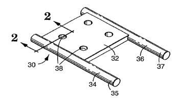
invention, a sacrificial core 30, as shown in Figure 1,
may be used. The external shape of the sacrificial
core 30 is generally similar to the external shape of
the unitary heat exchanger 10. More particularly, the
sacrificial core 30 includes a body forming portion 32,
a first manifold forming portion 34, and a second
manifold forming portion 36. The external surfaces of
the body forming portion 32, the first manifold forming
portion 34 and the second manifold forming portion 36
define the interior surfaces of the internal passages
22, 24 and 28 of the body portion 12, the first
manifold 14, and the second manifold 16, respectively.
The sacrificial core 30 can be formed as a
single unit, or may be made up of separate elements
15 adhered, fused or otherwise fixed together.
Specifically, the sacrificial core 30 including the
body forming portion 32 and manifold forming portions
34 and 36 can be formed as a unit by a molding process
or can be made separately and then fixed together by
melt fusing or adhesive. For example, the first and
second manifold forming portions 34 and 36 can be
formed together in one piece as part of a larger
supporting structure (i.e., U-shaped or rectangular),
and the body portion 32 can then be positioned on and
25 joined to the first and second manifold forming
portions 34 and 36 by melting and fusing the component
together at such joints.
Suitable materials usable for the sacrificial
core 30 include waxes, plastics and fusible metals or
30 alloys. Specifically, examples of suitable waxes
include "Machineable Wax" available from Freeman
Manufacturing and Supply Company of Cleveland, Ohio and
"Tuffy" injection wax available from Kerr Manufacturing
Company of Romulus, Michigan. An example of a suitable
35 plastic is a polyacetal sold by E. I. Dupont De Nemours
and Company of Wilmington, Delaware under the trademark
"DELRIN". Fusible or low melting point metals and
~ W095/09~36 1 71~ ~ ~ 15 PCT~S93/09531
alloys include the fusible alloys sold under the
trademark "INDALLOY" sold by Indium Corporation of
America of Utica, New York, particularly "INDALLOY 255'
and "INDALLOY 281~. It is understood that many other
5 waxes, plastics and metals could be used provided that
they can be melted, dissolved or decomposed without
substantially harming the material of the jet
impingement plate which is formed about the sacrificial
core 30 as described below.
It is understood that any suitable wax or
plastic or combinations and blends thereof could be
simply formed into the entire sacrificial core 30 by a
æingle molding step, such as by conventional injection
molding techniques. Moreover, when using a fusible
15 alloy, it is preferable to mold the fusible alloy into
the sacrificial core 18 by single molding step.
Alternatively, the sacrificial core 30 could be made by
a mach;n;ng process, wherein a block of suitable wax,
plastic or fusible metal could be machined down to the
desired core shape.
Referring back to Figures 1-4, the body
forming portion 32 of the sacrificial core 30 is
preferably provided with a plurality of holes 38
defined by internal surfaces 40. Such holes 38 are not
25 necessary, but are preferably provided to form mounting
apertures 42 through the body protion 12 of the jet
impingement plate 10 for mounting the jet impingement
plate 10 in position as desired. In this regard,
Figure 7 shows the jet impingement plate lO mounted in
30 position by supports 44 and screws 46, wherein the
screws 46 pass through the mounting apperatures 42 to
hold the jet impingement plate 10 against the supports
44. Any other mounting technique using such mounting
apertures 42 are contemplated. Moreover, if any other
35 mounting t~chn; que is used that does not require the
use of mounting apertures, then the mounting apertures
42 need not be provided but may be provided for
21~34
wos5lo9936 PCT~S~3tO9531 ~
s
16 `- -
structural integrity as further explained below.
The holes 38 and the internal surfaces 40 can
be made through the body forming portion 32 by drilling
or any other machining techn;que. Alternatively, the
holes 38 can be formed during the formation of the body
forming portion 32 of the sacrificial core 30. Such
may occur before or at the same time as the formation
of the first and second manifold forming portions 34
and 36. In any case, to form the holes 38 during a
lo molding step, the mold used for forming the body
forming portion 32 is provided with elements having
external surfaces that correspond to the internal
surfaces 40 of the body forming portion 32.
After the sacrificial core 30 is fully
formed, a unitary jet impingement plate 10 is formed
about the sacrificial core 30. Then, the sacrificial
core 30 is removed. In accordance with the present
invention, the unitary jet impingement plate 10 is
formed by a deposition step. Deposition is defined as
the controlled formation of material on an article from
the ambient solution, gases or mixtures thereof within
which the article is located. Deposition includes
electrochemical, chemical and physical techniques and
the like. Chemical deposition means techniques for
depositing body forming material as a result of a
chemical reaction, such as by chemical vapor deposition
(CVD). Physical techniques include deposition methods
such as spraying or sputtering techniques or the like.
Preferably, electrochemical plating is utilized.
Electrochemical plating is defined as the
deposition of a continuous layer of material onto an
article by the interaction in solution of a metal salt
and supplied electrons which are the reducing agent of
the metal salt. One type of electrochemical plating is
known as electroless plating within which the electrons
supplied for reduction of the metal salt are supplied
by a chemical reducing agent present in the solution.
woss/09936 PCT~S93/09S31
21 71 3~
17
Another type of electrochemical plating is known as
electrolytic plating, or more commonly as
electroplating, wherein the electrons used for
reduction of the metal salt are supplied by an external
source such as a battery, generator or other DC power
supply including rectifiers of AC current.
Furthermore, in electroplating, the object to be plated
must have or be provided with a conductive surface.
Furthermore, conventionally known pulse plating
t~chnigues can be optionally used where periodic
reversals of the current flow direction can be
controlled to enhance electroplating of certain metals,
particularly with copper.
A major advantage of electroless plating is
that material can be plated on properly prepared
non-conductors as well as further described below. The
most common metals that can be deposited by
electroplating or by electroless plating are nickel,
copper, gold and silver; however, many other known
metals, alloys, compounds and composites are also known
to be capable of deposition by electrochemical plating.
The formation of a self-supporting structure by
electrochemical plating, such as the unitary jet
impingement plate 10 of the present invention, is
hereinafter referred to as electroforming.
Referring again to Figures 3 and 4, the
unitary jet impingement plate 10 is formed, preferably
electroformed, substantially completely about the
sacrificial core 30 so as to substantially envelope the
sacrificial core 30 and with a shape generally similar
to the shape of the sacrificial core 30. Moreover, the
body portion 12 is integrally formed at the same time
with the first and second manifolds 14 and 16, and of
the same material. Furthermore, the forming material
is also deposited on the internal surfaces 40 of the
body forming portion 32 of the sacrificial core 30.
The result of such deposition of forming
woss/osg36 ~ 3 ~ ~ 18 PCT~593/09~3
material on the internal surfaces 40 within the
holes 38 is a plurality of apertured posts 48 that
integrally connect the first plate 20 and a second
plate 50 of the body portion 12. The number of posts
48 corresponds to the number of holes 38 defined by
internal surfaces 40. This formation of the apertured
posts 48 at the same time as the formation of the body
portion 12 and first and second manifolds 14 and 16
results in an integral structure that exhibits a
greatly improved strength and which can accommodate
substantially higher fluid pressures than that of heat
exchangers assembled from multiple parts. Furthermore,
the number of and pattern of the apertured posts 48 can
be chosen for specific strength characteristics in
addition to their use as providing mounting apertures
42.
When electrochemical deposition is used to
electroform the jet impingement plate 10, such
electrochemical deposition, particularly with
electroplating, may result in forming material being
deposited more rapidly at sharp edges of the
sacrificial core 30 than at other portions. Thus the
opposed corner edges 39 of internal surfaces 40 may
have a tendency to be electroplated faster than the
rem~in~er of the internal surfaces 40 depending on the
rate of deposition. It has been found that slower
rates of deposition reduce this tendency. Moreover,
the edges 39 can be chamfered or rounded as shown in
Figure 2 at 39' to enhance the formation of uniform
walls of the posts 48 and to increase post strength.
As mentioned above, the sacrificial core 30
may comprise a wax, plastic, fusible alloy or the like.
If the method of deposition of forming material used to
form the jet impingement plate 10 is electroplating,
then it is necessary that the outer surface of the
sacrificial core 30 onto which the forming material is
to be deposited be conductive. In the case of using a
~ wossloss36 21 7130 4 19 PCT~S93/09531
non-conductive wax or plastic sacrificial core, it is
firs^- -~ecessary to render the external surface thereof
conc ;ive. One manner of rendering the external
surface conductive is to treat the surface to form a
thin conductive layer thereon. This i.: conventionally
done by applying a very thin layer of ~-. conductor such
as silver on the external surface of those portions of
the sacrificial core 30 onto which deposition will take
place. Any of the known conventional layering or
coating techniques can be utilized to provide a thin
conductive layer including painting, spraying or an
initial use of electroless plating. Thereafter,
electroplating can be conducted as if the sacrificial
core 30 were totally metallic. If electroless plating
is to be utilized as the manner of forming the entire
jet impingement plate 10, then it may not be necessary
to first render conductive the sacrificial core 30.
Proper electroless plating may require certain surface
preparation steps, which are well known, and which may
vary depending on the metal to be deposited and the
core forming material. Typical steps include, in
order, treatment with an etchant, a neutralizer, a
catalyst, an accelerator and then the electroless metal
bath.
As shown in Figures 2 and 4, the sacrificial
core 30 including the body forming portion 32 and first
manifold forming portion 34 may be coated with a
conductive layer 52 when it is necessary to render the
external surfaces thereof conductive for plating by the
electroplating method. In contrast, it is not
nece~-CAry to provide the co,t,luctive layer 52 when
electroless plating is to be used as a manner of
electrochemical de~osition, if the sacrificial core 30
comprises a conduc~ive material such as a fusible
alloy, or if other deposition t~chn;ques are to be
used. As above, if electroless deposition is to be
conducted, other surface treatments may be required.
-
WO 95/09936 PCT/US93/09531 ~
2~r~ ~3o aS 20
Although it is preferable thatelectrochemical deposition be used to make the heat
exchangers according to the present invention, it is
contemplated that other deposition techniques, noted
above, could be used. For example, some metals, such
as nickel, are known to capable of deposition onto an
article by chemical vapor deposition (CVD) methods.
Moreover, other non-metals could be used and deposited
by a CVD method if the material deposited is strong
enough to withstand the fluid pressures and the heat of
a specific heat transfer application.
-After the forming material is deposited onto
the sacrificial core 30 and the unitary jet impingement
plate 10 is formed, the sacrificial core 30 must be
removed. In order to prepare for the removal of the
sacrificial core 30, some access must be provided from
external of the shell forming the unitary jet
impingement plate 10 to at least one of the passages
22, 24 or 28 formed within the unitary jet impingement
plate 10 by the sacrificial core 30. One manner to do
this, as shown in Figure 3, is to control the
deposition of forming material onto the sacrificial
core 30 so that at least a portion of one end of the
first or second manifold forming portions 34 or 36 of
the sacrificial core 30 is not covered by the forming
material. In other words, at least a portion of one of
the manifold forming portions 34 or 36 remains free of
forming material after the deposition step is complete
and the unitary jet impingement plate lo is fully
formed. As seen in Figure 3, an end 37 of the manifold
forming portion 36 is shown free of forming material.
This can be done in a variety of ways. If
the sacrificial core 30 is made of a non-conductive
material such as a wax or plastic and electroplating is
to be used as the deposition step, then by simply not
coating a portion of the manifold forming portion 34 or
36 with a conductive layer, such portion will remain
~ ~ W095/09936 ~ PCT~S93/09531
21 7130~ 21
free of forming material. In the cases where the
sacrificial core 30 is conductive or rendered
conductive and electroplating is to be used or where
electroless deposition or another chemical or physical
deposition method is to be used on a conductive or
non-conductive sacrificial core 30, then it may be
desirable to positively treat such a portion of the
manifold forming portions 34 or 36 so as to prevent
deposition of forming material thereon. This can be
done by wrapping or otherwise coating such a portion
with a tape or coating of material that will prevent
the deposition of forming material thereon. When using
electroless deposition, deposition can be prevented on
such a portion by coating or wrapping that portion with
a material or tape comprising any one of known
materials onto which electroless deposition does not
easily deposit. In the case of electroplating a
conductive sacrificial core 30, it is preferred to use
a non-conductive tape to provide the at least one
portion to which forming material will not be
deposited. It is, however, contemplated that any other
non-conductive coating, paint or the like could be used
instead. Moreover, it is preferred that more than one
access opening be provided by controlling the
deposition so that a plurality of sacrificial core
portions remain after deposition that are free of
forming material. More preferably, it is desirable
that such portions free of forming material be provided
at both ends of each of the manifold forming portions
34 and 36.
Another manner of providing the needed access
opening through the shell of the unitary jet
impingement plate lO is also illustrated in Figure 3,
which is used when the manifold forming portions 34 and
36 including the ends at 35 and 37 thereof,
respectively, are entirely covered by forming material.
The access opening can be provided by removing the
WO 95/09936 PCT/US93/09531 ~
~7130~ _
22
forming material from at least one of or all of the
ends 35 and 37. This removal can be easily done by
simply cutting away a portion of the manifolds 14 or 16
(as illustrated in Figure 3 where a portion of first
manifold 14 is cut away) including the ends 35 and/or
37. Other means for providing an access anywhere along
the first or second manifolds 14 and 16 such as
grinding, drilling or the like are also contemplated.
No matter how the access opening or openings
are provided through the shell of the unitary jet
impingement plate 10, the step of removing the entire
sacrificial core 30 follows. The preferred manner of
removing the sacrificial core 30 is by heating the
unitary jet impingement plate 10 including the
sacrificial core 30 to a temperature above the melting
point of the sacrificial core 30 but below the melting
point of the forming material'making the unitary jet
impingement plate 10. Thus, when heating is to be used
to melt the sacrificial core 30 the choice of materials
for the sacrificial core 30 is dictated by its melting
temperature as compared to that of the forming material
of the unitary jet impingement plate 10. The forming
material of the unitary jet impingement plate 10 is
preferably nickel or copper. Waxes and plastics such
as those noted above are in most cases suitable for
such sacrificial core use. Known low melting
temperature metals and alloys, also as noted above and
known as fusible metals and alloys, also work well.
To accomplish the removing step, the
combination of the unitary jet impingement plate 10 and
sacrificial core 30 are preferably placed in a heated
environment or heat is directly applied to the unitary
jet impingement plate 10. Furthermore, the access
opening is preferably provided in a position and held
in that position so that the flow of molten sacrificial
core material under the influence of gravity will
completely drain all of the sacrificial core forming
~ w~sssoss36 PCT~S93/09~31
21 71 3~4~ i t ~ ~
material from within the unitary jet impingement plate
10. It is also contemplated that one or more access
openings could be connected to a pressurized source or
a vacuum to assist in the removal of sacrificial core
material.
Alternately, the sacrificial core 30 can be
removed by chemically dissolving the sacrificial core
30 in a solution. In that case, the sacrificial core
30 should be comprised of a material which is easily
dissolved in a solution that will not substantially
harm the forming material of the unitary jet
impingement plate 10. In a similar manner, the
material of the sacrificial core 30 can be a material
which decomposes as a result of the application of a
controlling affect. For example, when the plastic
material known as DELRIN, discussed above, is used in
forming the sacrificial core 30, the application of
heat as the controlling affect causes such material to
decompose to formaldehyde which escapes as a gas.
After the deposition and core removing steps
have been completed, a further step in making the jet
impingement plate lo is the f orming of the jet
impingement orifices 18 through at least one of or both
of the first plate 20 and second plate 50. If the jet
impingement plate 10 is to direct the fluid jets 26
from only one side of the jet impingement plate 10,
then only one of the first and second plates 20 and 50
need be provided with jet impingement orifices 18. If
the jet impingement plate 10 is to be inserted between
components to be thermally affected, both the first and
second plates 20 and 50 may be provided with jet
impingement orifices 18. Figures 5 and 6 illus~rate
the jet impingement plate 10 with jet impingement
orifices 18 formed through the first plate 20.
The jet impingement orifices 18 can be formed
during the deposition step, as described below, or may
be made after the deposition step is complete and
woss/09936 PCT~S93/09s31
21713~ 2~
before or after the sacrificial core 30 is removed.
One method comprises simply drilling the jet
impingement orifices 18 through one or both of the
first and second plates 20 and 50. In such case, the
drill bit diameter would determine the diameter of each
of the jet impingement orifices 18. Moreover, the
number of and pattern that the jet impingement orifices
18 are provided through the first or second plate 20 or
50 is determined depending on the specific use of the
jet impingement plate 10. For example, as shown in
Figure 7, the jet impingement orifices 18 can be
specifically provided to concentrate the fluid jets 26
to impinge precisely located electronic components.
Thus, the pattern of jet impingement orifices 18 can be
any regular pattern for generally impinging an overall
component or the like the same thereover, or may be
specifically arranged in accordance with a
predetermined pattern of components.
Other machin;ng techniques are also
contemplated. Specifically, electron discharge
mach;ning (EDM) can be utilized. Such a machining
tec-hnique can similarly be controlled to provide the
jet impingement orifices 18 at a specific pattern, as
discussed above. Moreover, the EDM tec-hn; que provides
an additional benefit in that EDM can be controlled
while making the jet impingement orifices 18 to provide
complex profiles for the jet impingement orifices 18.
That is, the jet impingement orifices 18 need not be
formed cylindrically, but may include curves within the
side profile as viewed in cross-section.
Yet another method contemplated for providing
the jet impingement orifices 18 which also
advantageously permits control of the profile of each
jet impingement orifice 18 is illustrated in Figures 8-
10. The jet impingement orifices 18 are formed byproviding protuberances 54 ext~n~;ng from a modified
sacrificial core 56. As shown in Figure 8,
_ W095/09936 PCT~S93/09S31
21 71 3~
protuberances 54 are provided extending from a first
surface 58 and a second surface 60 of the modified
sacrificial core 56. The modified sacrificial core 56
is also preferably provided with at least one external
surface 62 which defines a hole through the sacrificial
core 56. The protuberances 54 are shown provided
ext~nd;ng from the first and second surfaces 58 and 60
to define the patterns of jet impingement orifices 18.
However, if heat transfer fluid is to be directed from
only one side of the jet impingement plate 10, then
protuberances 54 would be provided from one of the
first and second surfaces 58 and 60. Moreover, the
modified sacrificial core 56 can be formed by any of
the methods discussed above, including molding or
maçh; n; ng t~hn; ques. The protuberances 54 can be
formed by molding them with at least the body forming
portion of the modified sacrificial core 56.
Alternately, the protuberances 54 can comprise
separately formed elements such as shown at 54' which
are inserted within the body forming portion of the
modified sacrificial core 56. Such separately formed
elements 54' can be precisely located along the surface
of the body forming portion of the modified sacrificial
core and have the advantage that they are more easily
provided than making protuberances by molding or
maçh;ning.
The jet impingement plate 10 is formed in
accordance with the process discussed above by
depositing body forming material about the modified
sacrificial core 56. Again, any of the deposition
t~chn;ques discussed above are contemplated. However,
during the deposition step, body forming material
additionally forms about the protuberances 54 and over
the ends 55 thereof and makes bumps 64, as shown in
Figure 9, which extend outwardly from external surfaces
66 and/or 68 of the body portion 12 of the jet
impingement plate 10.
W095/09936 PCT~S93/09531 _
21~i3~
26
Once the jet impingement plate 10 is formed
about the modified sacrificial core 56, the sacrificial
core 56 iS to be removed and the jet impingement
orifices 18 must be finished. The jet impingement
5 orifices 18 can be completed either while the modified
sacrificial core 56 iS still within the jet impingement
plate 10 or after the sacrificial core 56 has been
removed. Preferably, the bumps 64 are ground or
otherwise machined from the external surfaces 66 and 68
of the jet impingement plate while the modified
sacrificial core 56 is within the jet impingement plate
10. Any other conventional techniques are contemplated
for removing the forming material comprising the bumps
64. In fact, since it is preferable to also finish the
15 external surfaces 66 and 68 of the jet impingement
plate 10 to ensure an even surface, the bumps 64 can be
removed during the same f;n; ~h; ng step. Once the bumps
64 are removed, the jet impingement orifices 18 are
fully formed. If the modified sacrificial core 56 i5
left within the jet impingement plate 10 during the
finishing step, it can thereafter be removed in any of
the removing manners discussed above. Advantageously,
the jet impingement orifices 18 provide additional
access openings through which the sacrificial core
25 material can be removed. If the sacrificial core 56 iS
removed prior to finishing the jet impingement orifices
18, then the jet impingement plate 10 is complete once
the jet impingement orifices 18 are done.
If the protuberances 54 are provided by
separately formed elements 54', discussed above, it may
be preferable or necessary to remove the elements 54 by
an additional step. If the elements 54' have a lower
melting temperature than the body forming material
making up the jet impingement plate 10, then they can
be removed by melting with the sacrificial core. The
elements 54' can also be removed by decomposition or
dissolving independant of how the rest of the
wos5los936 I 71 3 ~ ~ 27 PCT~S93/09531
sacrificial core is removed.
For example, the protuberances can comprise
elements 54' made up of copper wire inserted within a
wax or plastic sacrificial core 56. Then, nickel can
be deposited by electroplating. After an access
opening is provided, the sacrificial core 56 can be
removed by melting, while leaving the copper elements
54' within the jet impingement orifices 18. Therafter,
the copper elements 54' can be separately removed by
applying a conventional etchant within a conventional
stripping process that removes copper from nickel.
Specifically, a solution of 12 oz./gal. (90
grams/liter) of sodium cyanide and 2 oz./gal. (15
grams/liter) of sodium hydroxide is well known to strip
copper from nickel when applied in a conventional
stripping process.
As shown in Figure 10, the body portion 12 of
the jet impingement plate 10 is provided with jet
impingement orifices 18 directing heat transfer fluid
from opposed major surfaces of the body portion 12 of
the jet impingement plate 10. The jet impingement
orifices 18 are advantageously provided with curved
profiles which facilitate fluid flow through the jet
impingement orifices 18. Such profiles are defined by
the external profiles of the protuberances 54 from the
modified sacrificial core 56. Many other profiles are
contemplated which are limited by the ability to form
the modified sacrificial core 56. Another important
advantage of mak7ng the iet impingement orifices 18 in
the manner of Figures 8-10 is that such method
eliminates the drilling or machining of individual
holes, thereby reducing the amount of labor involved in
the jet impingement plate 10 production.
Yet another method of making the jet
impingement orifices 18 comprises using photoresist
technology. To do this, the sacrificial core 30, at
least at a portion of the body forming portion 32
W095/09936 PCT~S93109531
2 ~ ~3 a 4 28
thereof, is coated with a photoresist material.
Photoresist coatings change when the coatings are
exposed to light. Photoresist coatings particularly
suitable for the present invention are those which
exhibit a change in solubility and result in solvent
discrimination between areas exposed and unexposed to
light. Photoinitiated cross-linking and/or
polymerization decrease solubility, where as
photomodification of functionality and photodegradation
increase solubility. Thus, exposure of the coating to
a pattern of light results in solubility changes, and
resist images are formed by the boundaries of
solubility changes.
In the present case, the photoresist coating
is exposed to a predetermined pattern of light defining
the pattern desired for the jet impingement orifices
18. If the photoresist coating is decreased in
solubility by exposure to light, then the pattern of
light should correspond to the jet impingement orifices
18 themselves. If the photoresist coating is increased
in solubility by light, then the patter of light should
correspond to the areas between the jet impingement
orifices 18. In either case, the more soluble coating
portions can be waæhed away leaving the pattern of the
jet impingement orifices 18 on the body forming portion
32.
The photoresist coating in the pattern of the
jet impingement orifices 18, if non-conductive, can be
applied to a conductive or rendered conductive
sacrificial core so that during electroplating, body
forming material does not deposit on the photoresist
coating. In another way, the photoresist coating in
the pattern of the jet impingement orifices 18 can be
built up sufficiently so as to provide protuberances
similar to those shown in Figures 8-10, and the jet
impingement orifices 18 could be f;ni~he~ in the same
way. As above, any of the deposition methods could be
W095/09936 ~4 PCT~S93tO9531
29
used with this technique.
Thereafter, the sacrificial core 30 including
the photoresist material can be removed in accordance
with any of the methods discussed above. It may also
be necessary to further treat the jet impingement plate
10 to remove or dissolve the photoresist material in a
way that will not harm the body forming material. For
example, organic photoresist material could be
dissolved in a caustic solution, such as a sodium
hydroxide and water solution, without harming the body
forming material, such as nickel.
Although the deposition step of forming
material to form the unitary jet impingement plate 10
can be any known deposition ~echnique in accordance
with the above, a specific example of a suitable
preferred electroplating technique is described as
follows. In one example, a sacrificial core was
produced out of a 58% bismuth, 42% tin alloy, available
as "INDALLOY 281" having a melting point of 281F by
forming the sacrificial core within a mold. The mold
defined a pattern of holes within the sacrificial core.
Since the sacrificial core was made of a conductive
material, no additional step was required to render it
conductive. Next, the sacrificial core was mounted on
a brass turning rod for electroplating.
Thereafter, the sacrificial core and brass
turning rod were immersed in a nickel sulfamate bath
(not shown) containing 16 ounces/gallon of nickel; 0.5
ounces/gallon of nickel bromide; and 4.0 ounces/gallon
of boric acid. Also, 0.1 ounces/gallon of a
surfactant, namely "DUPONAL ME" available from E.I.
DuPont de Nemours and Company of Wilmington, Delaware,
was added to the bath to prevent H2 bubbles from
sticking to the surfaces of the sacrificial core and to
thereby reduce gas pitting. The remainder of the
plating bath was filled with distilled water. A
quantity of S-nickel anode pellets were contained
woss/09936 21~ 13 ~ ~ PCT~S93/09531 ~
within a titanium basket which was suspended in the
plating bath. A woven polypropylene bag was provided
surrounding the titanium basket for trapping
particulates within the plating bath. The plating bath
was continuously filtered through a 5 micron filter.
The temperature of the bath was maintained at 90 F.,
and a pH of 4.0 was maintained in the plating bath
solution. A current density of 10 amps per s~uare foot
was applied to the sacrificial core for 48 hours. The
voltage applied to the sacrificial core is a function
of the temperature of the bath to produce the desired
amps. Upon removal the sacrificial core included a
shell surrounding it made up of nickel having an
average uniform thickness of 24 mils (.610mm). As a
general rule, at 20 amps per square foot, the nickel is
deposited at a rate of approximately 1 mil/hr
(.0254mm/hr). Moreover, at 10 amps per square foot,
the nickel is deposited at an approximate rate of .5
mil/hr (.0127mm/hr). Slower formation generally
increases strength and improves uniformity of wall
thicknesses and posts.
After deposition, an access opening was
provided by cutting away a portion of the nickel shell,
and the nickel shell containing the sacrificial core
was heated to a temperature above the melting
temperature (281F) of the bismuth-tin alloy comprising
the sacrificial core, but below the melting temperature
of nickel. Such access opening was arranged downwardly
so that as the sacrificial core material was melted,
the material flowed out of the nickel shell. As a
result, clean passages were provided. Moreover, a
plurality of apertured posts were formed at each of the
locations of the holes according to the hole diameter
and spacing and pattern of holes provided within of the
sacrificial core.
Then, the jet impingement orifices were made
in the body portion at a desired pattern, spacing and
W095/09936 ~ 3l PCT~S93/09~31
diameter by EDM Machi~ing.
Unitary jet impingement plates formed in
accordance with the present invention are improved
structurally with the passage 24 of the body portion 12
in fluidic communication with one or both of the
passages 22 and 28 of the first and second manifolds 14
and 16, respectively, without leakage problems.
Moreover, the structural integrity is further improved
by the pattern of posts 48 which strengthen the body
portion 12. This strength is particularly important in
that the body portion 12 can handle heat exchange
fluids at relatively high pressures with a minimum of
plate deflection thereby providing high heat transfer
rates. Minimizing plate deflection is critical when
using the heat exchanger adjacent to certain components
such as electronic circuitry since deflection could
adversely affect the heat transfer fluid jets 26 and
thus the heat transfer rate and the components
themselves.
It is also noted, that throughout the
illustrations of the Figures, the height of the body
portion 12 with respect to the diameter, in
cross-section, of the first and second manifolds 14 and
16 is greatly exaggerated for clarity. That is not to
say that the jet impingement plate 10 cannot be formed
with such a dimensional ratio, but that it is
preferable to keep the thickness of the body portion 12
relatively thin as compared to the size the passages
within the manifolds so that a relatively large amount
of heat exchange fluid can be readily available to flow
into the body portion 12 and to easily position the
body portion 12 adjacent to a component or circuitry to
be cooled. Further in this regard, the body portion 12
can advantageously be positioned off center of the
plane connecting the axis lines of the first and second
manifolds 14 and 16 so that the body portion 12 can be
more easily positioned closer to a component.
W095/09936 PCT~S93/09531
~ 32
Referring now to Figures 11-13, yet another
embodiment of a jet impingement plate 70 formed in
accordance with the present invention is illustrated.
Specifically with reference to Figures 12 and 13, the
jet impingement plate 70 includes a manifold 72
provided along an edge of a body portion 76. The
manifold 72 is connectable to a fluid source as part of
a fluid circuit through which heat transfer fluid can
be circulated. The jet impingement plate 70 is
illustrated with only one manifold 72, but it is
understood that two or more of such manifolds can be
provided. Moreover, other manifolds can be further
connected with heat transfer fluid sources or drain
lines and reservoirs depending on the specific
application and heat transfer requirements. The jet
impingement plate 70 can be used as a heat source or as
a heat sink for heating or cooling a component or other
medium positioned adjacent to or flowing next to the
jet impingement plate 70.
The body portion 76 is integrally made with
and of the same material as the manifold 72 in
accordance with the forming method described above.
The body portion 76 is further provided with a pattern
of jet impingement orifices 78. The jet impingement
orifices 78 provide openings connected from the
internal passage 80 of the body portion 76 which is in
turn connected with the internal passage 82 of the
manifold 72. Thus, heat transfer fluid supplied within
the manifold 72 flows within the internal passage 82
thereof and then through the internal passage 80 of the
body portion 76 and is directed from the jet
impingement plate 70 through jet impingement orifices
78.
The jet impingement orifices 78 are
illustrated in a preferred pattern for providing
substantially equal heat transfer fluid impingement
over a surface of a component to thermally affected.
wos~/os~36 ~0~ PCT~S93/09531
As above, other patterns for the jet impingement
orifices 78 depending on the specific application and
the desired result are also contemplated. The specific
pattern illustrated in Figure 12 is also spaced to
accommodate posts 86 which are integrally connected
between a first plate 88 and a second plate 90 of the
body portion 76. The posts 86 are preferably provided
similarly as the apertured post 48 in the above
described embodiments for enhancing the structural
integrity of the jet impingement plate 70. As
discussed below, the posts 86 and the apertured posts
48 are instrumental in helping to reduce plate
deflection under relatively high fluid pressures when
using the jet impingement plate 70 for heating or
cooling a component by directing heat transfer fluid
against such a component. Moreover, the specific
pattern that the posts 86 and/or posts 48 are provided
affects such structural integrity.
In order to produce the jet impingement plate
70 including the posts 86, a sacrificial core 92 is
provided including a manifold forming portion 94,
connected with a body forming portion 98 by adhering,
melt-fusing or the like. The sacrificial core 92 has
an overall shape generally similar to the overall shape
of the jet impingement plate 70 which is formed by
depositing body forming material about the sacrificial
core 92. If an additional manifold or manifolds are
desired, additional manifold forming portions could be
connected with the body forming portion 98 in a similar
manner as manifold forming portion 94.
In order to make the posts 86, the
sacrificial core 98 is provided with holes lO0 provided
through the body forming portion 98 and in a pattern
corresponding to the desired pattern of the posts 86
within the body portion 76 of the jet impingement plate
70. Thus, during deposition of body forming material
about sacrificial core 92, body forming material
WO 9S/09936 - PCT/US93/09531
217130ll 34
deposits on internal surfaces of each of the holes 100
to integrally provide the posts 86 formed with the
first and second plates 88 and 90 of the body portion
76. Depending on the rate of body forming material
deposition and the control of such deposition, the
posts 86 may be solid, hollow or provided with an
aperture passing therethrough similar to the apertured
posts 48 of the earlier embodiments. Moreover, all of
the deposition techniques discussed above are
lo contemplated for making the jet impingement plate 70
with posts 86. Note that the posts 86 can be formed
closed at the tops and bottoms thereof but hollow in
the center because of the tendency during
electroplating for material to deposit faster at the
sharp edges of the sacrificial core 92. Slower
deposition rates and/or bevelled edges of the holes 100
reduce this tendency to provide stronger solid posts
86.
After the jet impingement plate 70 is formed
about the sacrificial core 92, the sacrificial core 92
is removed. As above, at least one access opening must
be provided through which the sacrificial core material
can be removed. Again, such removal may occur by
melting, decomposing or dissolving by solution the
sacrificial core 92. The access openings can be
provided in any of the manners discussed above.
The jet impingement orifices 78 can be
provided during the forming of the jet impingement
plate 70 or may be provided before or after the
30 sacrificial core 92 is removed. Again, the jet
impingement orifices 78 can be formed by a drilling or
machining process before or after the sacrificial core
92 is removed. Alternatively, the jet impingement
orifices 78 can be made during the deposition step by
forming the body forming portion 98 of the sacrificial
core 92 with protuberances (not shown) in the pattern
of the jet impingement orifices 78 or by using
woss/09936 1 71 ~q PCT~S93Jo9
photoresist technology, as described above. In the
case of providing protuberances, a fin;sh;ng step would
be required.
In accordance with preferred embodiments of
the present invention, it is an important aspect to
minimize plate deflection of the jet impingement plate
10 or 70 when it iF connected with pressurized fluid
sources and when t~--3 jet impingement plate 10 or 70 is
to be precisely positioned relative to a component,
such as electronic circuitry, which is to be thermally
affected. Excessive deflection of the body portion 12
or 76 could adversely affect the heat transfer
capability of such a jet impingement plate lO or 70 as
well as the electronic components themselves. In order
to minimize any adverse effects, it is preferable to
maintain plate deflection at any specific point below
.003 inches. Such is especially true for use in
densely packed electronic circuit environments of the
type where there is little room for tolerances and
where relatively high heat transfer rates are required.
In less sensitive environments, greater plate
deflection can be tolerated.
A jet impingement plate constructed in
accordance with the embodiment shown in Figures 11-13
was tested at 50 points over the body portion thereof
while connecting the manifold thereof to a fluid
pressure source of 25 p.s.i. and then to a fluid
pressure source of 50 p.s . Table 1 below shows the
average measured deflection at 25 p.s.i. and 50 p.s.i.
as compared to 0 pressure. No jet impingement orifices
were provided in the subject body portion of the jet
impingement plate so that the jet impingement plate
could be static ly pressurized.
W O9S/09936 ' PCT~US93/09531
36
T ~ LE 1
Deflection Deflection
Loca- (x 0.001") Loca- (x 0.001")
5tion @ 25 ~.~.i @ 50 P.~.i tion @ 25 p.s.L. @ 50 P.~.i.
1 0.5 1.2 2~ 1.0 2.3
2 1.2 2.1 25 1.4 2.6
3 1.7 2.9 26 1.8 3.7
~ 2.3 4.4 27 1.6 3.5
10 5 2.4 4.8 28 1.1 2.0
6 1.2 2.3 29 1.6 3.4
7 1.5 2.6 30 2.2 4.4
8 2.1 4.2 31 2.3 4.7
9 2.7 5.5 32 1.4 2.7
1510 0.9 1.6 33 1.5 3.1
11 1.6 2.4 3~ 2.0 3.9
12 2.1 3.6 35 2.4 4.4
13 2.4 4.5 36 2.4 4.9
1~ 2.7 5.0 37 1.2 2.4
2015 1.9 2.9 38 1.5 3.3
16 2.0 3.5 39 1.9 4.1
17 3.0 5.0 ~0 1.8 3.5
18 3.4 6.1 ~1 1.2 2.2
19 0.8 1.4 42 1.6 3.3
2520 1.7 3.0 ~3 1.8 3.4
21 2.3 3.9 4~ 1.8 3.6
22 2.4 5.0 ~5 1.6 3.3
23 2.1 3.5 ~6 1.3 2.8
2~ 1.0 2.1 ~7 1.8 3.9
3025 1.1 2.5 ~8 1.8 3.9
26 1.7 3.6 ~9 1.4 2.9
27 1.2 3.5 50 1.0 2.2
woss/oss36 PCT~S93/09S31
2~ 71 ~ 37
In order to perform the deflection tests, a
linear displacement transducer with a resolution to
o.OOOl inch was mounted in a fixed position over a
granite surface plate, and the jet impingement plate
was mounted in a fixture which held the plate by its
edges and allowed the plate to be moved under the
transducer to each test position. The 50 test points
-~re chosen in the areas of maximum deflection which is
midway between the structural posts. By holding the
jet impingement plate by its edges, the measured
deflection is the deflection from the plate center to
one side thereof. At zero pressure the height of each
test point above an arbitrary reference on the linear
displacement transducer was measured 3 times and
averaged. This zero height reference was then
subtracted from the height measurements made for each
test point at 25 p.s.i. and 50 p.s.i. to give the
deflection measureme~ts. The 25 p.s.i. and 50 p.s.i.
measurements were based on an average of 2 displacement
readings. Moreover, the entire set of 50 points were
mo~ed under the displacement transducer for one set of
readings before a second or third set of readings were
taken. The 25 p.s.i. data was taken after the initial
zero p.s.i. data. Then, the 50 p.s.i. data was taken
and finally a set of post pressurization zero p.s.i.
data was taken.
The tests were conducted on a body portion of
a jet impingement plate that had been machined to
finish the external surface thereof which determined
the final plate thicknesses. The mac~;n;ng operation
provided visible surface variations which resulted in
inner areas of the plate thickness of the jet
_~pingement plate body. As seen in Table l, the effect
on deflection of such thin spots were shown at points
17, 18, 35 and 36. Then, in order to verify that these
areas of greatest deflection were caused by plate
~h i nn j ng, cross-sections were taken through the plate
WO 95/09936 ~3~ ~ PCT/US93/09531
38
through lines connecting points 15-18 and 33-36. The
plate thickness at the included points were measured to
be as follows: point 15 = .023 inch; point 16 = .021
inch; point 17 - .018 inch; point 18 = .018 inch; point
33 = .020 inch; point 34 = .019 inch; point 35 = .018
inch; and point 36 = .018 inch. The thinnest points
16, 17, 35 and 36 were the same points having maximum
deflections. Points lS, 16 and 33 had thicknesses of
at least .020 inches and the deflection results were
well within acceptable limits. Lastly, the
measurements taken at zero pressure after the other
pressurization tests showed no significant permanent or
plastic deformation of the jet impingement plate body.
Yet another embodiment of a sacrificial core
230 in accordance with the present invention is
illustrated in Figure 14. The sacrificial core 230 is
advantageous in that the jet impingement plate formed
therefrom is divided into compartments. To accomplish
this, the body forming portion 232 of the sacrificial
core 230 is provided with a first manifold forming
portion 234 and a second manifold forming portion 236.
Preferably, holes 238 are also provided for forming
posts within the jet impingement plate formed
thereabout. In order to divide the body of the jet
impingement plate into separate compartments, the body
forming portion 232 is provided with a divider strip
240 of a material compatible with or the same as the
body forming material to be deposited. For example, if
electroplating is to be utilized, the divider strip 240
3 0 preferably comprises a conductive metal, and more
preferably of the same material to be deposited by
electroplating, i.e. a nickel divider strip 240 when
nickel is to be plated.
The deposited body forming material becomes
integral with the divider strip 240 along the exposed
edges thereof during deposition so that after the
sacrificial core 230 is removed two separate
W095/09936 PCT~Sg3/0953l
21 7
compartments are provided, each compartment with its
own manifold. Holes 242 are also preferable provLded
within divider strips 240 to anchor the divider strip
within the jet impingement plate by deposition.
Thus, each separate compartment can be
independantly controlled and supplied with heat
transfer fluid. Moreover, one of the manifolds could
be connected with a drain or suction line for removing
or recirculation heat transfer fluid. In the regard,
the jet impingement orifices could be advantageously
provided in one compartment for impinging heat transfer
fluid while being provided in the other compartment for
removing the heat transfer fluid. Furthermore, the jet
impingement orifices can be provided through opposite
plates of the jet impingement plate.
It is further understood that many
modifications can be made to the jet impingement plates
discussed above in accordance with the present
invention. In this regard, many other shapes or
geometries are contemplated for the body portion of
such jet impingement plate. Specifically, a jet
impingement plate could be provided with one or more
curved surfaces, or may be made in the form of a
geometric object such as a cone or the like. The shape
of such jet impingement plate being limited by the
ability to mold or otherwise make the sacrificial core
and the ability to deposit ody forming material on its
surfaces. The ability to make jet impingement plates
of complex shapes allows such jet impingement plates to
be designed to fit very nearly against components of
complex surfaces or geometries or to be used in
environments otherwise requiring such complex shapes.
For example, with reference to Figure 7, the
body portion 12 could be formed to include stepped
portions to correspond to the changes in levels of the
electronic circuit components of the illustrated
circuit board. The jet impingement orifices 18 could
wosslos936 ~- PCT~S93/0~53l _
2~ 3a~ -
all be substantially equidistant from the component to
which it is directed.
It is also contemplated that the manifolds
for the jet impingement plate can be integrally made
and connected with the body portions in many different
ways. Again, such is accomplished by appropriately
forming the sacrificial core. Specifically, the
manifold forming portion thereof could be provided to
extend longitudinally, circumferentially, along an edge
or any intermediate portion of any body portion of such
a jet impingement plate. Such is true of generally
planar body portions as well as those involving more
complex geometries.
Additionally, the materials used to form the
unitary heat exchanger can comprise any material which
can be deposited about the sacrificial core, which is
strong enough to handle the pressures associated with
the heat exchanger, and which is capable of maint~i n; ng
its structural integrity during the step of removing
the sacrificial core by melting, dissolving,
decomposition, or the like. Preferable materials
include nickel and copper which are easily
electrochemically applied by either electroless plating
or electroplating as described above.
It is also contemplated to apply forming
materials in layers which can be chosen depending on
the circumstances and environment of the application
for a specific heat exchanger. For example, it might
be desirable to first deposit a layer of nickel onto
the sacrificial core because of its strength and
corrosion resistant properties with certain fluids, and
then to deposit copper as the remainder of the body to
take advantage of its better heat conductivity. Such
controlled deposition can easily be accomplished by
electroplating.
Thus, the scope of the present invention
should not be limited to the structures described by
WO 95/09936 ~ ~ ' r PCTtUS93tO9531
41
the plural embodiments of this application, but only by
the limitations of the appended claims.