Language selection

Search

Patent 2171547 Summary

Third-party information liability

Some of the information on this Web page has been provided by external sources. The Government of Canada is not responsible for the accuracy, reliability or currency of the information supplied by external sources. Users wishing to rely upon this information should consult directly with the source of the information. Content provided by external sources is not subject to official languages, privacy and accessibility requirements.

Claims and Abstract availability

Any discrepancies in the text and image of the Claims and Abstract are due to differing posting times. Text of the Claims and Abstract are posted:

  • At the time the application is open to public inspection;
  • At the time of issue of the patent (grant).
(12) Patent: (11) CA 2171547
(54) English Title: DEVICE FOR IMPROVING THE EFFICIENCY AND CONTROLLABILITY OF SKIS
(54) French Title: DISPOSITIF SERVANT A AMELIORER LA PERFORMANCE DES SKIS
Status: Expired
Bibliographic Data
(51) International Patent Classification (IPC):
  • A63C 5/07 (2006.01)
  • A63C 5/075 (2006.01)
  • A63C 9/00 (2012.01)
  • A63C 11/00 (2006.01)
  • A63C 9/00 (2006.01)
(72) Inventors :
  • MAGGIOLO, MARCO (Italy)
(73) Owners :
  • MAGGIOLO, MARCO (Italy)
(71) Applicants :
  • MAGGIOLO, MARCO (Italy)
(74) Agent: BORDEN LADNER GERVAIS LLP
(74) Associate agent:
(45) Issued: 2005-11-15
(86) PCT Filing Date: 1994-09-08
(87) Open to Public Inspection: 1995-03-23
Examination requested: 2001-09-04
Availability of licence: N/A
(25) Language of filing: English

Patent Cooperation Treaty (PCT): Yes
(86) PCT Filing Number: PCT/EP1994/003015
(87) International Publication Number: WO1995/007737
(85) National Entry: 1996-03-11

(30) Application Priority Data:
Application No. Country/Territory Date
PD93A000180 Italy 1993-09-13
PD93A000227 Italy 1993-11-17

Abstracts

English Abstract


The device for improving the efficiency and controllability of skis has two
elongated shaped plate-like elements (12, 13), each having
one end (24 2'n provided with locking members (36, 38, 39b) for fixing to the
ski and another end (25, 26) provided with retention
members (39a) which allow the other end (25, 26) to slide longitudinally with
aspect to the ski (10). A toe unit (42) or heel unit (44) of a
ski binding is fixed proximate to one of the ends.


French Abstract

L'invention concerne un dispositif destiné à améliorer l'efficacité et la contrôlabilité des skis, ce dispositif étant doté de deux éléments allongés en forme de plaque (12, 13) ayant chacun une extrémité (24, 27) pourvue d'éléments de blocage (36, 38, 39b) servant à fixer ladite extrémité sur le ski, ainsi qu'une autre extrémité (25, 26) pourvue d'éléments de maintien (39a) lui permettant de glisser longitudinalement par rapport au ski (10). Une butée (42) ou une talonnière (44) d'une fixation de ski est fixée à proximité de l'une des extrémités.

Claims

Note: Claims are shown in the official language in which they were submitted.


10

CLAIMS:

1. A device for improving the efficiency and
controllability of a ski applicable at the upper center-of-
gravity region of a ski, comprising at least two elongated
shaped plate-like elements, each element having one fixed end
provided with means for fixing to a ski and another slideable
end provided with retention means which allow said slideable
end to slide longitudinally with respect to said ski, a toe
unit or heel unit of a ski binding being fixed proximately to
one of said ends for fixing therebetween a boat, wherein said
at least two plate-like elements are shaped so as to be both
locatable in the same region of the ski including the
center-of-gravity thereof so that the slideable end of a first
plate-like element and the fixed end of a second plate-like
element are arranged to the front and the fixed end of the
first plate-like element and the slidable end of the second
plate-like element are arranged to the rear, said toe unit and
said heel unit being fixed each at a respective one of said
longitudinally slideable ends of said plate-like elements so
as to avoid a fixed connection with said ski.

2. The device according to claim 1, wherein said at
least two plate-like elements are independent.

3. The device according to claim 1 or 2, wherein said
at least two plate-like elements at least partially overlap
each other and mutually cross.

4. The device according to any one of claims 1 to 3,
wherein said at least two plate-like elements are arranged at
least partially side by side.


11

5. The device according to any one of claims 1 to 4,
wherein said at least two plate-like elements are connected by
control means for controlling their mutual movements.

6. The device according to claim 5, wherein said control
means are constituted by at least one hydraulic actuator or
equivalent device controlled by sensors located on the ski.

7. The device according to any one of claims 1 to 6,
wherein the regions of said at least two plate-like elements
where the bindings are mounted are raised with respect to the
surface for resting on the ski.

8. The device according to any one of claims 1 to 7,
wherein said at least two plate-like elements are combined with
damping elements interposable between various overlapping
portions and between said portions of the plate-like elements
and the ski.

9. The device according to any one of claims 1 to 8,
wherein said at least two plate-like elements are combined with
damping elements which are arranged between said plate-like
elements, at least two of said damping elements at least
partially overlapping each other.

10. The device according to claim 9, wherein said damping
elements are constituted by layers of elastic materials.

11. The device according to any one of claims 1 to 10,
wherein said plate-like elements comprises each a lamina
including the ends, and the portions which are raised with
respect to the surface for resting on the ski, each of said
plate-like elements having two of said portions arranged at
mutually different levels which are connected by inclined


12

regions, one plate-like element having, in said inclined
regions, a large longitudinal slotted hole which is crossed by
the corresponding inclined and appropriately tapered portion
of the other plate-like element.

12. The device according to any one of claims 1 to 11,
wherein it comprises two plate-like elements that mutually
intersect at tapered portions thereof which are arranged side
by side.

13. The device according to any one of claims 1 to 12,
wherein the ends of said plate-like elements are flat and that
both the fixed ends and the movable ends have longitudinal
slotted holes for fixing to the ski by means of screws, said
screws passing through plates and elements that are shaped so
that each one has a portion that is shaped complementarily with
respect to the profile of the slotted holes and a
parallelepipedal portion that lies centrally with respect to
the complementarily-shaped portion, said portions being
substantially as thick as said plate-like elements, said shaped
elements each locking one plate-like element with one of their
portions and leaving the other plate-like element free to move.

14. The device according to any one of claims 1 to 13,
wherein said plate-like elements have holes for fixing a toe
unit and a heel unit of a ski binding.

15. The device according to any one of claims 1 to 14,
wherein it is integrated in the structure of the ski and/or of
the bindings.

Description

Note: Descriptions are shown in the official language in which they were submitted.


Image


Image


CA 02171547 2005-O1-07
3
control inaccurate.
A third type of device has a metal lamina which is
'_ shaped so as to have two raised regions at the regions
. where the heel unit and the toe unit are fixed.
The lamina is fixed to the ski both at the front and
at the rear, and a layer of elastic material is placed in
- the regions where said lamina is rai~~ed..
This device has the only positive effect of damping
vibrations that are transmitted from the ski to the
to athletes leg.
Disclosure of the Invention
Advantageously, embodiments of the invention may provide a new
device for improving the efficiency_and,controllability of
skis which eliminates or substantially reduces the
drawbacks described above in known types.
w ..- 15 Advantageously, embodiments of the invention may provide a
device that improves the efficiency and controllability of skis,
keeping the position of the boot unchanged with respect to
the ski and maintaining a center-of-gravity -position for
the skier.
20 Advantageously, embodiments of the invention may provide a
device that allows to control and adjust the longitudinal movement
of the ski.
Advantageously, embodiments of the invention may provide a
device that allows to achieve faster skiing.
25 Advantageously, embodiments of the invention may provide a
device that can also be configured so that it can absorb the
stresses induced in a substantially vertical direction on the ski,
Advantageously, embodiments of the invention may improve ski
control in any situation, especially when negotiating curves.
_ _____ . ~....a._~.. _ .,._4~.x~.._ .,, . ~._,..~~_~~~ ,~,~a~,3<~,.
~~~~~,~..~...~y.,~..~~.,__..~..___ _.._..._._._...____.,.~~,m


CA 02171547 2005-O1-07
4
Advantageously, embodiments of the :invention may provide a
device that can be manufactured with conventional equipment and ,
facilities.
According to an aspect of the present invention, there is
provided a device for improving the efficiency and controllability
of skis, characterized in that it comprises at least two elongated
shaped plate-like elements, each element having a first end provided
with means for fixing to the ski and a :>econd end provided with
~o retention means which allow said second end to slide longitudinally
with respect to said ski, a toe unit or heel unit of a ski binding
being fixed on one of said ends or adjacent thereto.
According to an aspect of the present invention, there is
provided a device for improving the efficiE=ncy and controllability
of a ski applicable at the upper center-of- gravity region of a ski,
Comprising at least two elongated shaped plate-like elements, each
element having one fixed end provided with means for fixing to a ski
and another slideable end provided with retention means which allow
said slideable end to slide longitudinally with respect to said ski,
a toe unit or heel unit of a ski binding being fixed proximately to
2(7
one of said.ends for fixing therebetween a boot, wherein said at
least two plate-like elements are shaped so as to be both locatable
in the same region of the ski including the center-of-gravity
thereof so that the slideable end of a first plate-like element and
25the fixed end of a second plate-like element are arranged to the
front and the fixed end of the first plac=e-like element and the
slidable end of the second plate-like element are arranged to the
rear, said toe unit and said heel unit being fixed each at a
respective one of said longitudinally slideable ends of said
plate-like elements so as to avoid a fixed connection with said ski .

CA 02171547 2005-O1-07
m
4a
Brief description of the drawings
Further characteristics and advantages of the
invention will become apparent from the following detailed
15 description of an embodiment thereof, illustrated only by
way of non-limitative example in the accompanying drawings,
wherein:
figure 1 is a perspective view of. the device applied
to a ski;
2o figure 2 is a longitudinally sectional perspective
view of the device:
figure 3 is an exploded view of tkie device;
figure 4 is a top plan view of the device;
figures ~ and ~ are longitudinal sectional views of
25 each end of the device:
figure 7 is a perspective view of an element included
in the device.
Ways of carrying out the invention
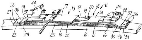
With reference to the above figures, a device


5

according to the invention, conveniently applied at the
upper center-of-gravity region of a ski 10, is generally
designated by the reference numeral 11 and comprises two
elongated shaped metal laminae, respectively a first lamina
12 and a second lamina 13, which are appropriately made of
aluminum alloy or equivalent materials.

The first lamina 12 and the second lamina 13 extend
upwardly from their ends, on inclined planes, so that they
are raised with respect to the surface for resting on the
ski 10; each lamina has two portions, respectively a first
lamina front portion 14, a first lamina rear portion 15, a
second lamina front portion 16 and a second lamina rear
portion 17, that lie at mutually different levels.

The first lamina rear portion 15 is located at a
different level with respect to the first lamina front
portion 14, and is connected thereto by a first lamina
inclined region 18. Similarly, the second lamina rear
portion 17 is located at a different level with respect to
the second lamina front portion 16, and is connected
thereto by a second lamina inclined region 19.

At the first lamina inclined region 18, the first
lamina 12 has a wide longitudinal slotted hole 20 which is
traversed by the second lamina inclined region 19, which is
appropriately tapered with respect to the rest of said
second lamina 13.

In this manner, the two laminae 12 and 13 mutually
intersect at the inclined regions 18,19 and the various
flat portions 14, 15,16, 17 overlap.

In particular, with reference to the figures, the
first lamina front portion 14 overlaps the second lamina


~~ 95/07737 ~~f//~P~~10~0~5
front portion 16 and the second laanina rear portion 17
overlaps the first lamina rear portion 150
The first lamina front portion 14 and the second
lamina rear portion 17 lie substantially at tae same levels
and the same is true for the first lamina rear portion 15
and the second lamina front portion 160
interposed between the upper surface of the ski 1~g and the
lower surfaces of the (first lamina rear portion 15 and the
second lamina front portion 160
2~ The front end 24 and the rear end 2~ of the first
25 and by the reference numerals 3~ and 31 for the second
lamina 13~
Said ends 240 250 26g 27 each have longitudinal
slotted holesg respectively 32~ 33 for the first lamina 12
and 34g 35 for the second lamina 13v for fixi~ag to the ski
3~ 10 bg~ means of screws 36 0


Image

Image


W~ 95/07737 9 ' ~C1'/~P9410301~
respect to each other according to the operating
conditions, in order to adapt the response of the ski for
example to changed conditions of the snow~covered surface
(frozen, powdery, compact, etc.).
This change in movement can provide for a variation in
the seepage rate between two chambers with hydraulic fluid
due to the variation of a port that allows flow between
them.
Said hydraulic actuator can be controlled by sensors
to which are located in various regions of the ski and are
sensitive to the stresses applied thereto.
Finally, it should be noted that in possible
technically equivalent elements.
In practice, the materials employed, so long as they
are compatible with the contingent use, as well as the
2o dimensions, may be any according to the requirements.

Representative Drawing
A single figure which represents the drawing illustrating the invention.
Administrative Status

For a clearer understanding of the status of the application/patent presented on this page, the site Disclaimer , as well as the definitions for Patent , Administrative Status , Maintenance Fee  and Payment History  should be consulted.

Administrative Status

Title Date
Forecasted Issue Date 2005-11-15
(86) PCT Filing Date 1994-09-08
(87) PCT Publication Date 1995-03-23
(85) National Entry 1996-03-11
Examination Requested 2001-09-04
(45) Issued 2005-11-15
Expired 2014-09-08

Abandonment History

Abandonment Date Reason Reinstatement Date
1998-09-08 FAILURE TO PAY APPLICATION MAINTENANCE FEE 1998-09-15
2000-09-08 FAILURE TO PAY APPLICATION MAINTENANCE FEE 2000-11-23

Payment History

Fee Type Anniversary Year Due Date Amount Paid Paid Date
Application Fee $0.00 1996-03-11
Maintenance Fee - Application - New Act 2 1996-09-09 $50.00 1996-07-31
Maintenance Fee - Application - New Act 3 1997-09-08 $50.00 1997-08-26
Reinstatement: Failure to Pay Application Maintenance Fees $200.00 1998-09-15
Maintenance Fee - Application - New Act 4 1998-09-08 $50.00 1998-09-15
Maintenance Fee - Application - New Act 5 1999-09-08 $75.00 1999-08-23
Reinstatement: Failure to Pay Application Maintenance Fees $200.00 2000-11-23
Maintenance Fee - Application - New Act 6 2000-09-08 $75.00 2000-11-23
Maintenance Fee - Application - New Act 7 2001-09-10 $75.00 2001-08-24
Request for Examination $200.00 2001-09-04
Maintenance Fee - Application - New Act 8 2002-09-09 $150.00 2002-08-30
Maintenance Fee - Application - New Act 9 2003-09-08 $150.00 2003-08-27
Maintenance Fee - Application - New Act 10 2004-09-08 $250.00 2004-07-30
Final Fee $300.00 2005-08-19
Maintenance Fee - Application - New Act 11 2005-09-08 $250.00 2005-08-30
Maintenance Fee - Patent - New Act 12 2006-09-08 $250.00 2006-09-01
Expired 2019 - Corrective payment/Section 78.6 $725.00 2007-01-12
Maintenance Fee - Patent - New Act 13 2007-09-10 $250.00 2007-07-30
Maintenance Fee - Patent - New Act 14 2008-09-08 $250.00 2008-07-30
Maintenance Fee - Patent - New Act 15 2009-09-08 $450.00 2009-07-31
Maintenance Fee - Patent - New Act 16 2010-09-08 $450.00 2010-07-29
Maintenance Fee - Patent - New Act 17 2011-09-08 $450.00 2011-08-05
Maintenance Fee - Patent - New Act 18 2012-09-10 $450.00 2012-07-24
Maintenance Fee - Patent - New Act 19 2013-09-09 $450.00 2013-07-25
Owners on Record

Note: Records showing the ownership history in alphabetical order.

Current Owners on Record
MAGGIOLO, MARCO
Past Owners on Record
None
Past Owners that do not appear in the "Owners on Record" listing will appear in other documentation within the application.
Documents

To view selected files, please enter reCAPTCHA code :


To view images, click a link in the Document Description column. To download the documents, select one or more checkboxes in the first column and then click the "Download Selected in PDF format (Zip Archive)" or the "Download Selected as Single PDF" button.

List of published and non-published patent-specific documents on the CPD .

If you have any difficulty accessing content, you can call the Client Service Centre at 1-866-997-1936 or send them an e-mail at CIPO Client Service Centre.


Document
Description 
Date
(yyyy-mm-dd) 
Number of pages   Size of Image (KB) 
Cover Page 2005-10-19 1 43
Representative Drawing 1997-06-16 1 11
Cover Page 1996-06-17 1 16
Abstract 1995-03-23 1 44
Description 1995-03-23 10 387
Claims 1995-03-23 4 144
Drawings 1995-03-23 3 108
Description 2001-10-18 10 626
Claims 2001-10-18 4 168
Claims 2005-01-07 3 142
Description 2005-01-07 10 611
Representative Drawing 2005-04-05 1 14
Correspondence 2007-01-23 1 14
Assignment 1996-03-11 5 213
PCT 1996-03-11 14 715
Prosecution-Amendment 2001-09-04 4 163
Correspondence 2002-01-29 1 22
Prosecution-Amendment 2007-01-12 2 61
Fees 1998-09-25 2 218
Prosecution-Amendment 2004-07-07 2 58
Prosecution-Amendment 2005-01-07 8 398
Correspondence 2005-08-19 1 27
Fees 1996-07-31 1 94