Note: Descriptions are shown in the official language in which they were submitted.
2171609
Automatic milking means removal device
FIELD OF THE INVENTION
The present invention relates to automatic milking machines
and, in particular, to automatic milking machines equipped
with an automatic mechanism for removing the milking
machine from an animal's udder.
BACKGROUND OF THE INVENTION
Devices for automatic removal of a milking means from an
animal°s udder are known. They include a motor, a drive
shaft operably connected to the motor, a rotatable removal
means, an elongated pulling means connected to the removal
means at its one end and arranged to be connected to the
milking means at its other end. The removal means is
adapted to pull the milking means off the udder by means of
the pulling means, when the removal means is rotated in a
given rotational direction, a gear change device positioned
between and coupled with the drive shaft and the removal
means, and a housing, which houses the gear change device,
the gear change device having a first gear change means
connected to the motor via the drive shaft and a second
gear change means connected to the removal means.
Such a removal device is known from WO 93/00002, and has
great advantages since it may be designed very compactly
and low in weight. In the known removal device, the
removal means comprises a cord drum with a cord adapted to
be connected to the milking means. However, the known
removal means has a drawback, since a mechanical resistance
must be overcome each time the cord is to be pulled out
from the cord drum to attach the milking means onto the
teats of an animal. The reason for this resistance is
CA 02171609 2001-08-07
2
partly due to the motor, which is directly connected to the
cord drum and resists rotation of the cord drum, and partly
due to the gear change device which increases the torsional
resistance of the cord drum to rotation. When pulling out
the cord from the cord drum, although the resistance of the
removal device is not particularly strong, with repeated
use the resistance becomes strenuous for a milker to
overcome.
SUMMARY OF THE INVENTION
This invention provides a device which is
characterized in that the gear change device has a third
gear change means movable between a first position in which
it is held substantially immovable relative to the housing
of the gear change device, and a second position in which
it is movable relative to the housing of the gear change
device, and in that the third gear change means is adapted
to operably connect the drive shaft of the motor to the
removal means via said first and second gear change means
when the third gear change means is in said first position
and to disengage the removal means from the drive shaft of
the motor when the third gear change means is in said
second position. Thus, the pulling means, a cord, for
example, may be easily pulled out from the removal means
for attachment of the milking means onto the animal's udder
without resistance from the motor and the gear change
device when the motor is not in operation. Preferably the
first, the second and the third gear change means have a
common axis, wherein the third gear change means is axially
2171609
3
movable along said axis between said first position, in
which it engages the housing of the gear change device, and
said second position, in which it is disengaged from the
housing and is rotatable about said axis.
It is furthermore advantageous that the third gear change
means forms a movable wall in a chamber in the housing of
the gear change device, that the housing of the gear change
device has at least one connecting channel for connection
of said chamber to a pneumatic source adapted to generate a
pressure differential with respect to atmospheric pressure
and wherein the third gear change means is adapted to be
moved along said axis to engagement with the housing of the
gear change device when said chamber is exposed to said
pressure differential.
Preferably, the third gear change means has an axial side,
relative to the axis of rotation, which side is designed
for engagement with the housing of the gear change device.
Advantageously, the pneumatic source is a vacuum source,
the chamber in the housing of the gear change device being
defined by said axial side of the third gear change means.
Advantageously, the motor is a pneumatically operable
sliding vane motor comprising a rotor arranged
eccentrically in a cylindrical housing, said housing of the
motor and the housing of the gear change device being
pneumatically interconnected, i.e. the interior of the
housing of the motor and the interior of the housing of the
gear change device are interconnected by a connecting
channel, so that there is fluid communication between the
two housings.
Preferably, the gear change device is a planetary gear set,
comprising a sun wheel, a crown wheel and at least one
planet wheel. Alternatively, any one of the three said
~171~09
gear change means can constitute any one of the said
wheels, i.e. the sun wheel, the crown wheel or the planet
wheel can permutably be connected to the motor, the cord
drum or the housing of the gear change device.
DRAWING SU1~IARY
The invention will now be described in detail with
reference to the accompanying drawings, in which
Figure 1A is a view of a longitudinal section through a
removal device according to a preferred embodiment of the
invention;
Figure 1B is an enlarged detail of a coupling portion of
the removal device shown in Figure 1A in an engaged state;
Figure 1C shows the same detail as shown in Figure 1B, but
with the coupling device in an unengaged state;
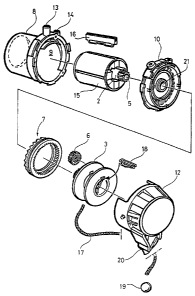
Figure 2 is an exploded view illustrating details of a
motor, a gear change device, a housing for the gear change
device, and a removal means of the removal device shown in
Figure 1A;
Figure 3A shows a cross-sectional view of the interior of
the housing illustrated in Figure 2;
Figure 3B shows an enlarged section taken along the line
IIIB-IIIB of Figure 3A;
Figures 4A and 4B show views of the opposite sides of a
gear change means of the gear change device illustrated in
Figure 2;
Figure 4C shows an enlarged section taken along the line
IVC-IVC in Figure 4B; and
z171so9
Figure 5 shows an end view of a further gear change means
of the gear change device mounted on the removal means
shown in Figure 2.
5 DETAILED DESCRIPTION OF THE PREFERRED EMBODIMENTS OF THE
INVENTION
The removal device according to the invention shown in
Figures 1A and 2 comprises a motor 1 with a drive shaft 2,
which is connected to a removal means in the form of a cord
drum 3 via a gear change device 4, for achieving required
torque. This preferred embodiment of the gear change
device 4 has planetary gearing enclosed in a housing, even
though other gear change devices could be used.
The planetary gearing 4 comprises a first gear change means
in the form of a sun wheel 5 connected to the drive shaft 2
of the motor, a second gear change means in the form of
three planet wheels 6 connected to the cord drum 3 and a
third gear change means in the form of a crown wheel 7
adapted to be releasably engaged with the housing of the
planetary gearing.
The motor 1 is equipped with a housing 8, which forms a
cylindrical chamber 9. One end of the housing 8 of the
motor is provided with a wall, which also forms one of the
walls for the housing of the planetary gearing and, hence,
constitutes an intermediate wall 10 between the chamber 9
of the motor and the chamber 11 of the planetary gearing 4.
The housing of the planetary gearing is formed by the
intermediate wall 10 and a casing 12. The chamber 11 of
the planetary gearing also houses the cord drum 3. The
intermediate wall 10 and the crown wheel 7 delimit a sub-
chamber lla of the chamber 11 (see Figure 1C). The housing
8 of the motor 1 is provided with an inlet 13 and an outlet
2171609
6
14 for connection to a source of vacuum (not shown) for
operation of the motor.
In the motor's chamber 9 is arranged a rotor 15 provided
with vanes 16 radially movable in relation to an axis A
through the rotor 15, which axis is coaxial with the
motor's 1 driving shaft 2. The rotor is arranged
eccentrically in the motor's chamber 9, so that the vanes
16 are forced to move in a radial direction during the
rotor's 15 rotation. When connected to the vacuum source,
there is a pressure difference in the motor's chamber 9.
The pressure difference acts upon the vanes 16, which in
turn force the rotor 15 to rotate.
A cord 17 is releasably connected at one end to the cord
drum 3 by means of a connection means 18. The connection
means 18 is arranged such that the cord 17 releases from
the cord drum 3 if the cord is subjected to external
pulling force that exceeds a preset limit after the cord is
completely unwound from the cord drum 3, and is held in
place only by the connection means 18. The cord 17 is
connected at its other end to the milking means (not
shown), as described in WO 93/00002.
The cord 17 is provided with a stop member in the form of a
ball 19. The ball 19 prevents the milking means from
hitting the removal means when the cord 17 is rewound. The
casing 12 is provided with a catch means 20, through which
the cord 17 freely runs, but which does not let the ball 19
through. In the motor's 1 rest position, which will be
described in more detail below, the catch means 20 catches
the ball 19 and prevents the cord 17 from being unwound
from the cord drum 3. In this way, the whole weight of the
milking means can be taken up by the removal device via the
catch means 20, when the motor 1 is in said rest position.
~''3
~~'~1609
Figure 3A is a front view of the part of the intermediate
wall 10, which forms an inner, axially directed wall of the
housing 10, 12 of the planetary gearing 4. Centrally in
the intermediate wall 10 an opening 21 is formed for
reception of the motor's drive shaft 2 with the sun wheel 5
arranged thereon. The intermediate wall 10 is provided at
its periphery with a ring 22 of an axially directed
friction enhancing means, which ring 22 is coaxial with the
opening 21 (see Figure 3B). The intermediate wall 10 is
furthermore provided with two passages 23 for pneumatically
connecting the sub-chamber lla to the motor's 1 chamber 9.
Alternatively, more or less than two passages can be
provided in the intermediate wall 10.
Figure 4A shows the planetary Bearing's 4 crown wheel 7
seen from a direction which faces away from the
intermediate wall 10 and towards the cord drum 3. The
crown wheel 7 is provided with a ring 24 with teeth
directed radially inwards. Figure 4B shows the side of the
planetary Bearing's crown wheel 7, which faces the
intermediate wall 10. On this side the crown wheel 7 is
provided at its periphery with a ring 25 of an axially
directed friction enhancing means, which ring is coaxial
with the axis of the crown wheel 7 (see Figure 4C).
The friction enhancing means on the intermediate wall 10
and the crown wheel 7, respectively, are shown in the
Figures 3A, 3B, 4B and 4C as teeth 22a, 25a having a form
substantially similar to a saw tooth, i.e. with non
uniformly inclined back rakes, 22b, 25b and 22c, 25c,
respectively. The back rakes of each tooth form angles a
and ,Q, respectively, with the base of the tooth, a being
about 20° and ,Q being about 55°. For reasons explained
below these friction enhancing means do not need to consist
of teeth 21a, 25a, but could be plain, substantially
planar, friction surfaces or a mechanical coupling in the
form of a pin or the like.
217109
s
Figure 5 illustrates one end wall 26 of the cord drum 3,
provided with three axes 27, each being provided with a
planet wheel 6 with teeth. The planet wheels 6 fit between
the crown wheel 7 and the sun wheel 5. Of course the teeth
of the crown wheel 7 and the sun wheel 5 fit the teeth of
the planet wheels 6.
FUNCTION
When milking is completed, which is sensed by a milk flow
meter known, but not illustrated, the removal device
receives a signal to start the motor 1 for winding the cord
17 onto the cord drum 3. The milking means, which is
connected to the cord 17, is thereby pulled away from the
teats of the animal.
When the signal is given that the motor 1 should start, the
motor 1 is connected to a vacuum source, which is suitably
the same as the one that operates the milking means. The
negative pressure which is thereby created in the chamber 9
of the motor drives the motor 1 so that the motor shaft 5
rotates. The passages 23 in the intermediate wall 10
pneumatically connect the chamber 11 of the planetary
gearing 4 to the motor's chamber 9, so that the planetary
Bearing's 4 chamber 11 and its sub-chamber 11a, is exposed
to the vacuum. Consequently, the crown wheel 7, which is
close to the intermediate wall 10 and in front of the
passages 23, is sucked against the intermediate wall 10 and
is retained there.
Accordingly, the crown wheel 7 of the planetary gearing 4
cooperates with the intermediate wall 10 as parts of a
coupling device K (see Figure 1) between the motor 1 and
the cord drum 3. It should be noted, though, that the
crown wheel 7 need not necessarily be retained
pneumatically. It could also be retained in a plain
mechanical way by locking by means of pins or by a clamping
~;i.
~~7~sos
9
means of any known kind. Alternatively, it could also be
retained in an electromechanical way, for example by means
of a magnet or a solenoid, which pushes or pulls the crown
wheel 7 against the intermediate wall (see Figure B).
The engagement of the crown wheel 7 with the intermediate
wall 10 is achieved by means of two different forces,
namely a force acting axially relative to the crown wheel
7, which is achieved by means of the vacuum in the sub-
chamber 11a, and a force acting in the circumferential
direction of the crown wheel 7, which is achieved by means
of the friction enhancing means. It is to be understood
that the said engagement can be achieved by means of a
friction engagement between plane friction surfaces. In
such a case, the friction enhancing means may consist of
plane friction coatings. However, it is desirable that
different properties of engagement in different directions
of rotation of the crown wheel 7 be achieved and for this
reason the differently back raked teeth 22a, 25a are
preferred. The reason for this is that the substantially
axially directed back rakes 22b, 25b of the teeth on the
crown wheel 7 and the intermediate wall 10 provide a
relatively stable engagement of the teeth 22a, 25a in the
winding direction, whereas the more sloping back rakes 22c,
25c provide extra protection against overload for the
removal device, since they will without difficulty
disconnect under a load opposite to the winding direction.
With the crown wheel 7 anchored on the intermediate wall
10, the sun wheel's 5 rotation of the planet wheels 6
results in rotation of the planet wheels along the crown
wheel 7 and about the sun wheel 5, such that the cord drum
3 is turned. The cord drum 3 thus winds the upcord 17 so
that the milking means is pulled off the animal's udder.
Before the cord is pulled in too far on the cord drum 3, it
is stopped by the catch means 20, which catches the ball 19
arranged on the cord 17.
ø.i
2171609
to
When the milker is to move the milking means and the
removal device to the next animal to be milked, the milker
releases the connection means from the vacuum source. This
motor 1 therefore returns to the rest position described
above and is no longer driven because there is no longer a
negative pressure in the chamber 9 of the motor.
Furthermore, a vacuum is no longer transmitted through the
passages 23 in the intermediate wall 10, which means that
the crown wheel 7 is disengaged from the intermediate wall
10 (see Figure 1C).
When the crown wheel 7 is freely movable it can move with
less friction than the motor 1 on which the sun wheel 5 is
arranged, the planet wheels 6 engage the sun wheel 5 which
only moves insignificantly or not at all. Accordingly, the
cord drum 3 is now disengaged from the motor 1. The ball
19 is still in the catch means 20, which prevents rotation
of the disengaged cord drum 3.
When the next animal is to be milked, the milker first
disengages the ball 19 from the catch means 20. Owing to
the freely movable crown wheel 7 the milker can thereafter
pull out the cord from the removal means without resistance
from the motor 1 and the planetary gearing 4. The milking
means which is now connected to the source of vacuum, will
be attached to the animal's teats, where it remains until a
signal is given that milking is finished.
The invention is not limited to the embodiment shown here.
Hence, the crown wheel 7 may be arranged to be affected by
a positive pressure instead of by vacuum. Nor is it
necessary to use a pneumatic sliding vane motor. A
pneumatic cylinder, an electrical motor or a spiral spring
could also be used to achieve rotation of the cord drum for
the winding of the cord.