Note: Descriptions are shown in the official language in which they were submitted.
WO 95/11471 ;~ 5 PCT/US9~/12110
12AT~ ON~ l~FTROP~ CUB~ CORNl~l~ ARTICT.~ AND
M~THOn OF MA~U~A~TrJl~F.
t~ross-Reference to Related Application
This is a Continll~tion in Part of U.S. Patent Application
Serial No. 08/139,448, Raised Zone Relroreflective Cube Corner Article and
M[ethod of Manllf~ctllre~ filed October 20, 1993.
Field of the Invention
This invention relates to retroreflective articles having
prismatic relroreflective elements.
Back~roun~
Many types of retroreflective articles are known, and are
made in a variety of ways. One common type of relrorenective article uses
transparent microspheres, typically with hemispheric retroreflectors
thereon. FY~mples of this type of retroreflector are disclosed in U.S. Patent
2,407,680 (Palmquist), U.S. Patent 3,190,178 (McKenzie), and U.S. Patent
4,025,159 (McGrath).
Another type of retroreflective article includes prismatic
designs incorporating one or more structures commonly known as cube
corners. Retroreflective sheeting which employs cube corner type
re~ective elements is well known. An example of such designs is shown
in U.S. Patent 3,684,348 (Rowland).
WO 95/11471 PCT/US9~/12110
The manufacture of retroreflective cube corner element
arrays is accomplished using molds made by different techniques,
including those known as pin bundling and direct machining. Molds
manufactured using pin bundling are made by assembling together
5 individual pins which each have an end portion shaped with features of a
cube corner rell~oreflective element- For example, certain pin bundled
arrays permit elaborate assembly into various pin structural
configurations. U.S. Patent No. 3,926,402 (Heenan et al) and U.S. Patent
No. 3,632,695 (Howell) are examples of pin bundling.
The direct machining technique, also known generally as
ruling, comprises cutting portions of a substrate to create a pattern of
grooves which intersect to form cube corner elements. The grooved
substrate is referred to as a master mold from which a series of
impressions, i.e. replicas, may be forme~ In some instances, the master is
15 useful as a retroreflective article, however replicas, including multi-
generational replicas, are more commonly used as the retroreflective
article. Direct ma~hining is an excellent method for manufacturing
master molds for small micro-cube arrays. Small micro-cube arrays are
particularly beneficial for producing thin replica arrays with improved
20 flexibility, such as continuous rolled goods for sheeting purposes. Micro-
cube arrays are also more conducive to continuous process manufacturing.
The process of manufacturing large arrays is also relatively easier using
direct machining methods rather than other techniques. One example of
direct machining is shown in U.S. Patent No. 4,588,258 (Hoopman).
25 S1lmmary of Invention
The invention comprises a method of manufacturing a cube
corner article comprising the steps of providing an initial non-unitary
cube corner element array comprising a plurality of geometric structures
including cube corner elements, producing a replica of the cube corner
30 element array as a substrate suitable for forming retroreflective surfaces,
and then removing part of the substrate material comprising the replica to
form at least one cavity bounded by side walls in the replica at a depth at
WO 95/11471 PCT/US94/12110
21717~
least that of the cube corner elements. The replica is then replicated to
produce an Arl~iitio~l directly machinable substrate suitable for forming
r~ rellective sl~rfAces, the substrate comprising at least one raised section
having side walls at a height at least that of the cube corner ~lem~nts.
5 Then at least one raised section is directly machined to form a raised zone
comprising a plurality of geometric structures including cube corner
~lPmentc bounded by at least two sets of parallel grooves.
The in-~enlion comprises a method of manufAct~lring a cube
corner article comprising the steps of providing an initial directly
10 machinable substrate formed as an initial non-unitary cube corner
elPment array comprising a plurality of geometric structures including
cube corner elemel~tc~ and removing part of the substrate material
comprising the array to form at least one cavity bounded by side walls in
th,e substrate at a depth at least equal to the height of the cube corner
15 ~lem-ents~ The initial substrate is then replicated to produce an ~ tiona
directly machinable substrate suitable for forming relrorenective sllrfAces,
with the additional directly machinable substrate comprising at least one
raised section having side walls at a height at least that of the cube corner
~l~m~nt~. At least one raised section is then directly machined to form a
20 zone comprising a plurality of geometric structures including cube corner
elements bounded by at least two sets of parallel grooves.
The invention comprises a cube corner article which is a
machined replica of a non-unitary initial array comprising geometric
structures including cube corner elements. The article has at least one
25 directly machined raised zone of geometric structures including cube
corner elements.
Brief nescription of nrawiT~
Figure 1 is a plan view of a conventional pin bundled full
cube corner element array master for manufacturing retroreflective
30 sheeting.
Figure 2 is a section view taken along line 2-2 of Figure 1.
WO 95/11471 ~ ~ 7 1 ~ 4 5- PCTIUS9~/12110
Figure 3 is a plan view of a conventiQI~l pin bundled directly
m~rhilled cube corner element array master for manufacturing
relLorerlective sheeting.
Figure 4 is a sectior~ view taken along lines 4~ of Figure 3.
Figure 5 is a plan view of a relroreflective replica of the
master shown in Figure 3.
Figure 6 is a section view taken along lines 6-6 of Figure 5.
Figure 7 is a plan view of a directly machinable substrate
comprising a cavity portion formed in parallel alignment with one of the
groove sets formed in the substrate.
Pigure 8 is a section view taken along lines 8-8 of Figure 7.
Figure 9 is a plan view of an additional directly m~thinable
substrate formed by replicating the substrate shown in Figure 7.
Figure 10 is a section view taken along lines 10-10 of Figure 9.
Figure 11 is a plan view of a directly machined substrate in
which a plurality of zones of geometric structures included cube corner
elements is shown.
Figure 12 is a section view taken along lines 12-12 of Figure
11.
Figure 13 is a plan view of a directly machined substrate
comprising a plurality of zones of geometric structures and intersecting
raised zones.
Figure 14 is a section view taken along lines 14-14 of Figure
13.
Pigure 15 is a plan view of a directly machined cube corner
article which is a replica of a zoned substrate formed by directly machining
a series of substrates.
Figure 16 is a section view taken along lines 16-16 of Figure
15.
Pigure 17 is a plan view of a directly m~rhined cube corner
article comprising a plurality of zones of retroreflective cube corner
WO95/11471 2 1 7 t 7 ~ ~ PCT/US9~/12110
.
element~ having diverse cube geometry and orientation, including one
raised zone.
Figure 18 is a section view taken along lines 18-18 of Figure
17.
Figure 19 is a plan view of a directly machined cube corner
article comprising a plurality of zones of reLl~oreflective el~mPnts having
different geometries, inc~ ing at least one raised zone.
Figure 20 is a section view taken along lines 20-20 of Figure
19.
Figure 21 is a plan view of a directly machined cube corner
article comprising a plurality of zones of geometric structures including
relrore~lective cube corner elements, including one zone comprising cube
corner elem~nt~ having heights greater than cube corner elements in
adjacent zones.
Pigure 22 is a section view taken along lines 22-22 of Figure
21.
Figure 23 is a plan view of a directly machined cube corner
article comprising a plurality of retroreflective cube corner elements and
one raised section.
Figure 24 is a section view taken along lines 24-24 of Figure
23.
Figure 25 is a plan view of a directly machined cube corner
article comprising a plurality of zones of geometric structures including
reLloreflective cube corner elements, and one raised zone not bounded by
grooves in a groove set.
Figure 26 is a section view taken along lines 26-26 of Figure
25.
Figure 27 is a plan view of a directly machined cube corner
article comprising a plurality of zones of geometric structures including
retroreflective cube corner elements, and a plurality of multiple non-
inler~ing raised zones.
wo g~/l14712 1 7 1 7 4 5 PCT/US9~/12110
Figure 28 is a section view taken along lines 28-28 of Figure
27.
Figure 29 is a section view taken along lines 29-29 of Figure
27.
5Figure 30 is a plan view of an initial pin bundled directly
machinable substrate in which a plurality of geometric structures have
been formed by directly machining one set of parallel grooves in the
substrate.
Figure 31 is a section view taken along lines 31-31 of Figure
10 30.
Figure 32 is a section view taken along lines 32-32 of Pigure
30.
Figure 33 is a plan view of a replica of the substrate of Figure
30.
15Figure 34 is a section view taken along lines 34-34 of Figure
33.
Figure 35 is a section view taken along lines 35-35 of Figure
33.
Figure 36 is a plan view of the replica article shown in Figure
20 33, comprising ~ tional grooves formed in raised sections within the
orientation of the initial groove set.
Figure 37 is a section view taken along lines 37-37 of Figure
36.
Figure 38 is a section view taken along lines 38-38 of Figure
25 36.
Figure 39 is a plan view of a directly mAchined two groove set
cube corner article comprising a plurality of zones of retroreflective cube
corner elements.
Figure 40 is a section view taken along lines 40-40 of Figure
30 39.
Figure 41 is a section view taken along lines 41-41 of Figure
39.
WO95/11471 2 1 7 1 7 ~ ~ PCT/US94/12110
Figure 42 is a plan view of a pin bundled full cube array with
a direclly m~chined cavity.
Figure 43 is a sectior view taken along line 4~43 of Figure 42.
Pigure 44 is a plan view of a cube corner article formP~ as a
m~chinP~l replica of the array shown in Figure 42.
Figure 45 is a section view taken along line 45-45 of Figure 44.
lE:igure 46 is a section view of a cube corner article having a
plurality of zones of geolnetric structures including raised zones and cube
corner elements which form boundary edges of separation surfaces.
Figure 47 is a section view of a cube corner article comprising
a plurality of zones of geometric structures inrlll~ling raised zones suitable
for holding a sealing medium above geometric structures in at lease one
other zone.
Pigure 48 is a section view of a cube corner article comprising
15 a plurality of raised zones and including a plurality of raised sections
suitable for holding a sealing medium above zones comprising
re~,rerlective surfaces of geometric structures.
ne~A~ nesrription of Ill~ r~l;ve ~mho~ ent~
The manufacture of retroreflective cube corner element
arrays is accomplished using either unitary or non-unitary, i.e. assembled,
molds made by dirrerent techniques. These techniques include, inter alia,
those known as pin bundling and direct machining. ~ssemhled molds
manufactured using pin bundling, such as initial non-unitary master
25 mold 2 shown in Figure 1 and Pigure 2, are made by assembling together
zones 4 of individual pins which each have an end portion shaped with
features of a cube corner relroreflective element, as shown by full cube
corner elements 6, 8. Certain pin bundled arrays permit elaborate assembly
into various pin structural configurations. U.S. Patent No. 3,926,402
30 (Heenan et al), is one example of pin bundling.
Direct machining is often a preferred method for effif~i~ntly
manufacturing master molds for small microcube arrays. This is due to
WO 95/11471 2 1 7 1 7 4 5 PCT/US9~/12110
the advantages derived from directly machined substrates in the
production of thin replica arrays with improved flexibility, and the often
relatively more efficient manufacturing steps when compared with pin
bundling. An example of a direct machined substrate is taught in U.S.
5 Patent No. 3,712,706 (Stamm). The Stamm patent and U.S. Patent No.
4,588,258 (Hoopman) are each examples of structures forn~e-l by single or
multiple passes of a machine tool having two opposing cutting surfaces for
cll~ing grooves to form cube corner optical faces in a substrate.
It is recognized that directly machined grooves are ~rererably
10 machined as groove sets comprising a plurality of separate and parallel
grooves. In the direct m~rhining patent examples cited above, at least
three groove sets are required. However, examples of direct machining
involving only two sets of grooves are shown in U.S. Patent No. 4,349,598
(White) and U.S. Patent No. 4,895,428 (Nelson et al).
Retroreflective cube corner element arrays are typically
derived from matched pairs of cube corner retroreflecting elements, i.e.
cubes which are geometrically congruent and rotated 180-, such as cube
corner element 12 and cube corner element 14 shown in directly machined
pin bundled cube corner article 16 of Figure 3, which is simil~r to the non-
20 unitary substrate shown in U.S. Patent 4,243,618 (Van Arnam). The cube
corner elements in article 16 are bounded by grooves having identical
groove depths, and are the same element length. The highest points in
conventional three groove arrays are defined by the cube peaks 20. All of
the elements in article 16 are the same height above a common rererence
25 plane 18, as shown in Figure 4. Other examples of this fu~ mental
matched pair concept relating to conventional cube arrays is shown in U.S.
Patent No. 3,712,706 (Stamm), U.S. Patent No. 4,588,258 (Hoopman), U.S.
Patent No. 1,591,572 (Stimson), U.S. Patent No. 2,310,790 aungerson), and
U.S. Patent No. 5,122,902 (Benson), and German patent reference DE 42 42
30 26~ (Gubela).
Referring again to Figure 3 and Figure 4, one example of
conventional non-canted cube corner elements is shown having three
WO 95/11471 PCT/US94/12110
~ ~ 1 7 1 7~5
sides when viewed in plan view, and having an equilateral triangle
formed at the base of each cube corner reflecting element. These cube
corner reflecting elPnlent~ are formed by three groove sets directly
machined into a substrate. Figure 3 shows a plan view of a directly
5 m~t~hine~l cube corner article useful as a non-unitary master mold which
is then replic~ted, or plated, to form a unitary cube corner article 22 as
shown in Figure 5 and Figure 6. Referring again to Pigure 3, the grooves
25 in non-parallel groove sets mutually intersect at representative
loc~Pons 27.
Figures 3 and 4 disclose cube corner element relro~eflective
arrays comprising non-canted cubes which have individual symmetry axes
19 that are perpentiic~ r to a plane 18. The symmetry axis is a central or
optical axis which is a trisector of the internal or dihedral angles rlefin~rl by
the faces of the element. However, in some practical applications it is
advantageous to cant or tilt the symmetry axes of the matched pair of cube
corner retroreflective elements to an orientation which is not
perpendicular to the base plane. The resulting canted cube-corner
~lemPnt~ combine to produce an array which relr~reflects over a wide
range of entrance angles. This is taught in U.S. Patent No. 4,588,258
(Hoopman), and is later shown below in relation to other figures. Canting
may be in either a forward or backward direction. The Hoopman patent
includes disclosure of a structure having an amount of cant up to 13 for a
refractive index of 1.5. Hoopman also disdoses a cube with a cant of 9.736.
This geometry represents the maximum forward cant of cubes in a
conventional directly machined array before the grooving tool damages
cube optical surfaces. The damage normally occurs during form~tion of a
third groove when the tool removes edge portions of adjacent Pl~ments.
U.S. Patent No. 2,310,790 aungerson) discloses a structure which is canted
in a direction opposite that shown in the Hoopman patent
~;or these conventional arrays, optical performance is
conveniently clefimPrl by the percent of the surface area that is actually
relrorenective, i.e. which comprises an effective area of active aperture.
WO 95/11471 PCT/US94/12110
217174~ --
The percent active aperture varies as a function of ~e amount of canting,
refractive index, and the entrance angle.
At non-zero entrance angles, conve~tionAl directly mArhinP~l
arrays display, at most, two di~rent aperture shapes of roughly sirnilAr
5 size. These result from the single type of geometrically congruent mAtrh~P~l
pairs of convelltiortAl cube corner Plem~Prltc. r~Ante-l conventional cube
corner arrays exhibit simil~r trends, although ~e shape of the aperture is
affected by the degree of canting.
Some conventional cube corner arrays are manufactured
10 with A~ itional optical limitations, perhaps resulting from cAnting or
other design features, to provide very specific performance under certain
circumstances One example of this is the structure disclosed in U.S. Patent
4,895,428 (Nelson et al), and which is shown in a multiple zone modified
configuration in several figures below. In these geometries, the cube
15 corner PhPmPntC are each canted in a backward direction to the point that
each of the base triangles is eliminAted.
Referring again to convPnti~Al arrays, U.S. Patent Nos.
4,202,600 (Burke et al), and 4,243,618 (Van Arnam) disclose, and
incorporate by reference, the triangular based cube corner reflecting
20 elements or prisms shown in Stamm. The Burke et al. patent discloses
tiling of these prisms in multiple differently oriented zones to produce an
appearance of uniform brightness to the eye when viewed at a high angle
of incidence from at least a minimum expected viewing distance. The
Van Arnam reference discloses use of pin bundling to create disoriented
25 patterns of cube corner trigonal pyramids and cutting a grid of grooves into
a mold formed by the bundled pins. In this manner, the pins may be cut
so that sheeting formed from the molds contains raised grids for bonding a
backing m~teriAl to the sheeting.
Some pin bundled relrorenective articles also comprise a grid
30 or ridge-like structure, such as the examples shown in U.S. Patents
4,243,618 (Van Arnam), 4,202,600 (Burke et al), 4,726,706 (Attar), 4,208,090
(He~n~n), 4,498,733 (Flanagan), 3,922,065 (Schultz), 3,417,959 (Schultz), and
WO95/11471 ~ ~ J ~ 7~5 PCT/US94/12110
11
3,924,929 (Holmen). Another ridge-like structure in a relrorellective article
is taught, primarily, for a microsphere or beaded sheeting constrltctior-, in
U.S. Patent No. 4,025,159 to McGrath Ridge-like structures are lltili7e~ in
these examples to provide raised grids for bon~ing a backing material to
5 the sheeting. Another example of ridge-like structures in pin bl~n~lle~l
r~trorenective articles is shown within U.S. Patent 3,632,695 (Howell), in
which each ridge-like structure is shaped as a lens area to tr~ncmit, rather
than reflect, light from a source.
The invention comprises retroreflective cube corner articles
10 and sheetings, and methods of manufacture, which substAn~i~lly advance
the state of the art of cube corner elements. This results from use of novel
mAnllfacturing processes, and directly machined cube corner article
designs which greatly enhance the retroreflective performance and
produce arrays having novel raised zones.
Figure 7 is a plan view and Figure 8 is a section view of a
replica 70 of a directly m~thinable substrate having geometric patterns
which are ~imil~r, in part, to the patterns shown in sheeting 22 shown in
Figure 5. In this embo~iment, replica 70 comprises zone 73 having a
plurality of geometric structures incl~ ing identical cube corner elements,
20 such as individual elements 75. Part of the substrate material is removed
to form at least one cavity 77 bounded by a base 78 and side walls 79 in the
substrate, as shown in the section view of Figure 10. Side walls 79 are
m~t hined to a depth D' which is at least that of the depth D" of the initial
sets of parallel grooves. In addition to using the preferred substrate
25 materials discussed below, it must be possible to separate replicas from the
original pattern or substrate. In some cases, this requires the use of a
parting layer between the original and the replica substrates. The parting
layer permits separation of replicas by ~revenling arlllesion between the
nl~teri~ls of the original and replica materials. Parting layers may consist
30 of a variety of materials such as an induced surface oxidation layer, an
interme~ te thin metallic coating, c~emic~l silvering, or combinations of
different materials and coatings.
WO 95/11471 PCT/US9`1/12110
217~745
12
An ~ ho~Al unitary substrate is then formed as a replica 80,
as shown in Figure 9, of directly machinable replica 70. SPIection of an
appropriate additional unitary substrate must take into account the
requir~mentC of rep~ tion accuracy of features in the initial substrate, the
5 suitability of the ~ itiorl~l unitary substrate for formation of geometric
structures inrlllciirlg retroreflective cube corner elements, and the ability toseparate the ~d~litio~Al substrate from the initial substrate without ~3~m~ge
to any ~eometric feature. A non-unitary initial substrate, a unitary replica
70, or a unitary replica 80 is each ~rererably formed of material suitable for
10 creating relrorenective surfaces in this embodiment. A substrate suitable
for forming retroreflective surfaces according to this invention may
comprise any material suitable for forming directly machined grooves or
groove sets. Suitable materials should machine cleanly without burr
formation, exhibit low ductility and low graininess, and maintain
15 ~iimen~ion~l accuracy after groove formAtion. A variety of materials such
as machinable plastics or metals may be utili7e~l. Suitable plastics
comprise thermoplastic or thermoset materials such as acrylics or other
materials. Suitable metals include aluminum, brass, nickel, and copper.
Preferred metals include non-ferrous metals. Preferred machining
20 materials should also minimi7e wear of the cutting tool during formAtion
of the grooves. As a result of cavity 79 being formed in the replica of the
initial directly machinable substrate, unitary replica 80 comprises at least
one raised section 100 as shown in Figure 9 and Figure 10. .Acl~litional
grooves and/or cavities may then be directly machined into replica 80, or
25 multi-generational unitary replicas, to form a plurality of zones of
geometric structures including cube corner ~l~mPnh 75 bounded by at least
two seb of parallel grooves, as ~iscll~se~l below.
It is recognized that while the above embodiment uses an
initial non-unitary substrate similAr to that shown in Figures 3 and 4, the
30 type of cube corner array shown in Figures 1 and 2 may also be used as an
initial non-unitary substrate. It is further recogni7e~ that the machining
techniques described below may utilize any of the various known types of
WO 95/11471 PCT/US94/12110
2~717~3
s-cs~mhled non-unitary substrates including the types described above for
initial non-unitary substrates. Non-unitary initial substrates may even
compAse geometric structures which are not cube corner elements. Figure
7 ~i~closes replica joining line 76 of a joining line from an initial non-
5 urutary substrate. Replica joining lines may or may not be apparent inreplicas of an initial non-unitary substrate according to this inv~ntion
Figure 11 and Figure 12 disclose in plan view and section
view respectively another embo~liment of the invention in which an
~ldition~l directly machinable unitary substrate 140 comprises zones of
10 cube corner elements including zone 142 and zone 146. Zone 146 may be
originally formed as a raised section which is then directly machined using
a three groove set pattern. The direct machining of a raised section
produces a raised zone, which comprises a plurality of geometric st-l-/ctures
including cube corner elements bounded by at least two sets of parallel
15 grooves. In one embodiment, such as that shown in Figure 12, the ~7. ttom
of the deepest groove in at least one raised zone 146 is machined to a depth
which is higher relative to a common rererellce plane 151 than the highest
structure in any zone which is adjacent to the raised zone. Figure 13 and
Figure 14 disclose in plan and section view respectively a substrate 160
20 comprising a plurality of intersecting raised zones 14~, also manufactured
using a three groove set pattern.
As shown in Figures 11-14 for embodiments including
directly machined raised zone arrays, the groove sets in a raised zone are
~rererably parallel to at least one groove set in zones, e.g. portions of the
25 array, adjacent to raised zones. Also, the total width of a raised zone is
preferably an integral multiple of the distance between grooves in groove
sets in zones adjacent to the raised zone. This is achieved, in one
embodiment, by creating an initial substrate with a cavity suitable for
forming a raised section which is bounded by grooves from at least one
30 groove set in a first cube corner Plenlent array zone. This is particularly
useful when the cubes in adjacent zones are the same geometry but
different size, i.e. geometrically similar. This results in fewer
WO95/11471 2 1 7 1 7 ~ 5 PCT/US9~/12110
14
relLoreflective element~ which are damaged during the manufacturing
process and therefore considerably improves the performance of
retroreflective sheetings using this construction. In addition, the
machining of raised zones does not initially require machining the surface
5 of a substrate with the same high measure of flatness as when
m~nl1f~ctllring raised sections.
Conventional cube corner retroreflective element designs
include structural and optical limitations which are overcome by use of
these raised zone cube corner retroreflective element structures and
10 methods of manufacture. Use of this new class of retroreflective cube
corner element structures and manufacturing methods permits diverse
cube corner el~ment shaping. For example, cubes in a single array may be
readily manufactured with raised discontinuous geometric structures
having different heights or dir~erent shapes. Use of these methods and
15 structures also permits manufacture of cube arrays which have highly
tailorable optical performance. For example, at many entrance angles,
including at zero entrance angle, raised multiple structure arrays
outperform conventional arrays by exhibiting higher percent active
apertures, multiple active aperture shapes, or by providing improved
20 divergence profiles, or both. Raised multiple structure manufacturing
techniques may also produce enhanced optical performance resulting from
closely spaced intermixed cubes with different active aperture shapes and
sizes. This presents more uniform appearances of raised nnultiple
structure arrays over a wide range of viewing ~1ishnces under both day and
25 night observation conditions. These advantages of raised multiple
structure cube corner elements and zones enhance the usefulness of
articles having these features. Such articles include, for example, traffic
control materials, retroreflective vehicle markings, photoelectric sensors,
directional reflectors, flexible retroreflective arrays, and reflective garments30 for human or animal use.
As ~i~ctlsse~ above, many limiting cases of conventional cube
corner element design are surpassed through use of raised multiple
WO 95/11471 PCT/US94/12110
21717~15
structure methods of manufacture. In some raised multiple structure
designs, such as that shown in substrate 140 in Figure 11, cube surfaces
having some conventional cube geometries may occur as part of a
plurality of cube types in a single array. However, the rlclrm~l limits of
5 convPntioll~l cube shapes and perror~ ces are not similArly bounded
using raised multiple structure methods and skuctures.
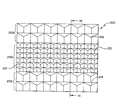
Figure 15 and Figure 16 are plan and section views
respectively of an alternate embodiment substrate 200, which is a
machined replica of a two groove set modified unitary substrate formed
10 from an initial non-unitary cube corner elPment array. Substrate 200
comprises a plurality of zones 206, 208 of geometrically simil~r cube corner
elements 212, 216. Substrate 200 includes a raised zone 208 which
comprises a plurality of geometric structures including cube corner
elements 212 which are a different size and which are at a different height
15 above a common reference plane 214 than cube corner elements 216 in
zone 206. Substrate 200 is particularly useful in applications requiring high
brightness at high entrance angles such as pavement mArkers~ approach
m~rkers, channel m~rk~rs, roadway dividers, barriers, and ~imilAr uses.
Figure 17 and Figure 18 are plan and section views
20 respectively of another alternate embodiment substrate 250, which is a
machined replica of a three groove set modified unitary substrate formed
from an initial non-unitary cube corner element array. Substrate 250
comprises a plurality of zones 252, 254, including at least one raised zone.
Raised zone 254 comprises a plurality of geometric structures including
25 cu~e corner elements 260 which are a different size and shape, and are at a
dif~erent height above a cQInmQn rererence plane 263, than cube corner
elements 265 in zone 252. Raised zone 254 is shown with one secondary
groove set having directly machined secondary grooves 266 in parallel
relation with grooves in an adjacent zone. In this embodiment, two of the
30 grooves in the adjacent zone bound raised zone 254 so that the total width
of the raised zone is an integral multiple of the distance between the
grooves in the groove set in the zone adjacent to raised zone 254. Another
WO95/11471 2 1 7 1 ;7~5 PCT/US9~/12110
secondary groove set having directly m~hined secondary grooves 267 is
arranged in non-parallel relation with any grooves in adjacent zones.
Grooves 268 in a primary groove set are also arranged in non-parallel
relation with any groo~res in ~ c~nt zones. It is recognized that any of the
5 grooves may be designated for parallel alignment with grooves in an
adjacent zone, depending on the desired orientation.This permits
orientation of cube corner elements 260 in virtually any manner to
optimize optical pelrormance~ however, this is accomplished without
riAm~ge to any structures in A~j~cent zone 252.
Figure 17 further discloses a raised zone multiple structure
cube array 250 having at least one zone 254 in which primary grooves 268
do not pass through the secondary grooves 266, 267 at the mutual
intersection locations 269 of the secondary grooves. Primary grooves 268
are equally spaced and centered on secondary groove intersection locations
15 269. Array 250 presents yet another novel feature of raised multiple
structure cube corner technology. In particular, a method is disclosed for
manufacturing a cube corner article by directly machining three non-
parallel non-mutually intersecting sets of grooves. Preerably, these sets
intersect at included angles less than 90. It is recognized that certain
20 machining imprecisions may create minor, unintentional separation
between grooves at intersections. However, this aspect of the invention
involves intentional and substantial separation. For example, a separation
distance between the intersections of the grooves within two groove sets
with at least one groove in a third groove set which is greater than about
25 0.01 millimeter would likely provide the advantages of this feature.
However, the precise minimum separation distance is depen~ent on the
specific tooling, substrate, process controls, and the desired optical
performance sought.
Non-mutually intersecting groove sets create multiple
30 different geometric structures including cube corner elements with
different active aperture sizes and shapes. Entire arrays, such as array 250,
may even be formed with cube corners created by a combination of
WO 95/11471 17 PCT/US94/12110
mutually and non-mutually intersecting groove sets. The position of the
groove sets is controlled to produce m~Yim-um total light return over a
desired range of entrance angles. Also the distance between grooves in at
least one groove set might not be equal to the distance between grooves in
5 at least another of the groove sets. It is also possible to machine at least
one set of parallel grooves into a substrate in a repeating fashion with the
set comprising a distance between grooves which is optionally v~riAble at
each machining of the set. Also, a portion of any one of the grooves may
be machined to a depth that is difrere..t from at least one other groove
10 depth.
Pigure 19 and Pigure 20 are plan and section views
respectively of another alternate embodiment substrate 270, which is a
modified replica of a mixed two groove set and three groove set modified
unitary substrate formed from an initial non-unitary cube corner Pl~mPnt
15 array. ~ubstrate 270 comprises a plurality of zones 274, 276, including at
least one raised zone. Raised zone 276 comprises a plurality of geometric
structures including cube corner elements 280, formed with three groove
sets, which are a dir~rel.t size and shape, and arê at a dirrer~l-t height
above a common reference plane 283 than cube corner elements 285,
20 formed with two groove sets, in zone 274. Indeed, raised zone 276
comprises grooves which are machined to a depth which is higher relative
to common referel-ce plane 283 than the highest structure, e.g. cubes 285,
in the adjacent zone 274. Substrate 270 comprises cube corner Plementc
which are sperifit~lly tailored to provide peak light return at high entrance
25 angles, although other combinations are also useful.
Figure 21 and Figure 22 are plan and section views
respectively of another alternate embodiment substrate 290. Substrate 290
comprises a plurality of zones 293, 295, including at least one raised zone.
Raised zone 295 comprises a plurality of 'dentical geometric structures
30 including cube corner elements 297. Cube corner elements 297 and cube
corner elements 293 share a comTnon base reference plane 300, which aids
considerably in processing the article. Cube corner elements 297 are a
WO 95/11471 PCT/US9~112110
2t7t~
18
different size, and have peaks at a different height above a common
rererence plane 300, than cube corner ~l~mPnt~ 303 in zone 293. Substrate
290 comprises certain structures that are higher than others to help
minimi7e rl~m~e to cubes during processing and handling of the replica.
5 Figure 21 and Figure 22 show spacing W between grooves in groove sets in
zones ~jAcent to the raised zone, and the corresponding spacing 2W
between grooves bounding the raised zone. It is desirable to use this
m~rhining method which results in an article having at least one raised
zone with directly machined cube corner ~l~ment~ in which the groove
10 sets in a raised zone are parallel to a groove set in at least on portion of the
article ~ cent to the raised zone, and the distance between grooves in a
groove set in a raised zone is an integral multiple of the distance between
grooves in groove sets in areas in at least one portion of the article
adjacent the raised zone. This manufacturing innovation permits
15 significant reduction and/or elimin~tion of l~m~ge to optical structures
adjacent to the raised zones.
Variable groove spacing within any groove set may also be
used to produce raised multiple structure cube arrays with additional
beneficial features. In such cases, the spacing of the primary grooves
20 within a groove set relative to the secondary groove intersections is varied
in a repeating pattern throughout array. A wide range of aperture sizes
and shapes will result in this array, with a corle~ponding improvement in
the uniformity of the return energy pattern or divergence profile of the
reL~ore~lected light due to diffraction. Proper pl~cem~rlt of grooves can be
25 utilized advantageously during design to provide optimum product
performance for a given applic~tion. Another beneficial feature ir~ les
ma~llf~ctllre of a raised zone having cube corner elements which are of
substantially i-l~ntic~l shapes to cube corner elements in portions of the
array adjacent to the raised zone, but with the raised zone cube corner
30 elements exhibiting different optical performance than cube corner
elements in the adjacent portions of the array.
WO95/11471 2 1 7 3 ~ ~ 5 PCT/US94/12110
19
Raised sections and raised zones may be manufactured in
dif~r~nt shapes using the methods of this invention, as shown in Figure
23 and Figure 24, in which a six sided raised section 315 is formed in
s~sllate 319. l~ise~ section 315 is surrounded by zone 322 having a
plurality of cube corner elements 325. Raised sectiQn 315 is manllf~ctl7red
by replit A~ng a n~o~lifie~l replica of an initial non-unitary substrate. Part of
the substrate material in the modified replica is removed to form at least
one cavity. The cavity is formed using any known technique, such a
electrical-discharge machining, photo-etching, or other precision
techniques. The cavity is bounded by side walls in the replica at a depth at
least that of the cube corner Pl~ment~ formed by the groove sets in ~ c~rlt
areas. The replica is then replicated to produce a cube corner article
co~prising a zone 322 and at least one raised section 315 having side walls
at a height at least that of the height of cube corner elements formed in the
adjacent zone.
Figure 25 and Figure 26 disclose a raised zone article simil~r
to the raised section article shown in Figure 23 and Figure 24, but with a
raised zone shape which is not bounded by a groove in a groove set.
Substrate 330 comprises a raised zone 333 having a plurality of geometric
structures including cube corner elements 335. The raised zone is
surrounded by adjacent zone 338 having a plurality of cube corner
elements 340. In the embodiment of Figures 25-26, cube corner el~nlent~
335, 340 are geometrically imil~r. It is recognized, however, that cube
corner elements in the zones may have diverse geometries and
orientations to control optical pelforlnance characteristics and may be
positioned at dif~erellt heights relative to comrnQn reference plane 341.
The invention permits numerous com~inations of structures previously
unknown and not possible within the art of retroreflective cube corner
e1Prnent design and manufacturing technologies.
Figures 27-29 disclose views of substrate 350 in which there is
forl~nerl a plurality of both different and repeating patterns of geometric
structures including cube corner elernents in multiple independent
WO 95/11~171 PCT/US9~/12110
2t~45
discontinuous raised zones 352, 354. A portion of a zone may be separated
from another portion of the zone by other structures such as a raised
sect;c!n or a raised zone. All portions of a zone should be m~ntlf~chlred at
the same time and must not interrere with the machining of any other
5 raised structure. This multiple independent zone capability effectively
reduces the number of replication cycles necess~ry to produce arrays
having greater than two zones. The raised zones are bordered by an
c~nt zone 365 having a plurality of cube corner ~ mpnh 370.
Figures 30-32 disclose an initial pin bundled non-unitary
10 substrate 390, comprising a plurality of pins 400, in which one initial
groove set 398 is m~rhined in initial raised areas 395. Substrate 390 may
either have initial recessefl areas 393 or it may require forming these areas
after m~rhining groove set 398. Figures 33-35 disclose views of a replica 402
of m~rhine~l substrate 390. In replica 402, the features of substrate 390 are
15 invelled so that the grooves formed by groove set 398 are now peaks in a
zone 406, which is lower than adjacent zone 410.
Figures 36-38 disclose substrate 402 which is further m~rhined
with additional ~rooves 417 to produce a plurality of machined raised
sections 415. Marhine~l raised sections 415 each have structures which
20 share a base plane 421 which is higher than the base plane 424 of the
simil~r structures in ~ cent zones. Also, the peak height of structures in
a-ljAc~nt zones is the same. This is also shown in Figure 40. Figures 39-41
each disclose substrate 402 which is further machined with an additional
groove set comprising a plurality of grooves 427 to form zones of cube
25 corner elements. Zone 436 comprises cube corner element~ 438, and zone
442 comprises cube corner elements 445. The method disclosed in Figures
30~1 produces the zoned cube corner articles of Figures 39-41 using only
one replication step.
Another embodiment of the invention comprises
30 m~ntlf~cture of a raised zone cube corner article which also requires only
one replication step after machining an initial non-unitary substrate.
Referring to Figure 42 and Figure 43, initial pin bundled full cube corner
WO95/11471 2 1 7 i 7 ~ 5 PCT/US94112110
~?lPmprlt array 447 is shown in plan and section view respectively. Array
447 comprises a plurality of geometric structures including cube corner
elements 448. Part of the directly m~rhinAhle substrate material comprising
the initial non~ y array is removed to form at least one cavity 449
5 bounded by side walls 450 in ~e substrate at a depth at least equal to the
height H of the cube corner elements. Replication of the initial substrate is
then performed to produce an A~ itional directly machinable substrate 452,
shown in Figure 44 and Figure 45, which is suitable for forming
relrore~lective surhces. The replica comprises at least one raised section
10 having side walls at a height at least that of the cube corner element.c.
Direct machining using the various techniques described above of at least
on,e raised section then forms a raised zone 454 comprising a plurality of
geometric structures including cube corner elements bounded by at least
two sets of parallel grooves. In this embodiment, a taper of appro~imAtPly
15 5- is shown for ease of separation of a replica.
Figure 46 discloses a section view of a substrate 455,
mAnl-fActured as described above as a machined replica of a modified
unitary substrate forme-l from an initial non-unitary cube corner element
array. Substrate 455 comprises zones of geometric structures including
20 cube corner elements having different heights and different geometries.
Figure 46 shows a plurality of germetric structures, such as structures 459,
460, each comprising a lateral face 461, 462 formed by a groove in a groove
set. In at least one zone, lateral faces of the geometric structures form
boundary edges 463 of a separation surface 466. The lateral faces may
25 include cube corner element optical surfaces as well as non-optical sllrfAces on cube corner or other geometric structures. A separation surface 466
may have flat or curved portions when viewed in cross secti~ n
Other embo~ ents of this method include creation of an
article, or replicas of the article, which further modify the shape of the
30 retroreflected light pattern. These embodiments comprise, for directly
maehined arrays, at least one groove side angle in at least one set of
grooves which differs from the angle r ecessAry to produce an orthogonal
WO 95/11471 PCT/US9~112110
~71745
22
intersection with other faces of elements defined by the groove sides. This
is also stated in terms of a sheeting having a plurality of either directly
marhine~ or pin bundled cube corner elements each having at least one
dihedral angle which is not 90. ~;imil~rly, at least one set of directly
5 machined grooves may comprise a repeating pattern of at least two groove
side angles that differ from one another. This feature may also be stated in
terms of a sheeting having a plurality of either directly mA~-hined or pin
bl~ndl~-l cube corner elements each having, in a repeating pattern, at least
one dihedral angle which is not 90 . Shapes of grooving tools, or other
10 techniques, may create cube corner elements in which at least a significant
portion of at least one cube corner elPrnent optical face on at least some of
the cubes are arcuate. The arcuate face may be concave or convex. The
arcuate face, which was initially forme~ by one of the grooves in one of the
groove sets, is flat in a direction substantially parallel to said groove. The
15 arcuate face may be cylindrical, with the axis of the cylinder parallel to said
groove, or may have a varying radius of curvature in a direction
perpenAi~ll~r to said groove.
Raised zone multiple structure geometries are particularly
beneficial for use in applications requiring retroreflective sheeting having
20 substantial total light return, such as traffic control materials,
reLloreflective vehicle markings, photo-electric sensors, signs, internally
illuminated relroreflective articles, reflective garments, and retroreflective
markings. The enhanced optical performance and design flexibility
resulting from raised zone multiple structure techniques and concepts
25 relates directly to improved product performance, cost efficiencies, and
marketing advantage.
Total light return for retroreflective sheeting is derived from
the product of percent active aperture and relrorenected light ray intensity.
For some combinations of cube geometries, entrance angles, and refractive
30 index, signific~nt reductions in ray intensity may result in relatively poor
total light return even though percent active aperture is relatively high.
One example is relLoreLlective cube corner element arrays which rely on
WO95/11471 2 1 7 1 7 ~ 5 PCT/US94/12110
.
23
total internal reflection of the rellorenected light rays. Ray intensity is
substantially reduced if the critical angle for total internal reflection is
eXcee~e~l on any one of the cube faces. Metallized or other reflective
co;~tingc on a portion of an array may be lltili7e~1 advantageously in such
5 sit~ tions. For Px~tnple, a parhcular raised zone which has cube surfaces
contacting a sealing medium will often be more reflective when the
sllrhces have a reflective coating. Alternately, a portion may comprise an
entire array.
Separation surfaces may be advantageously utilized to
10 increase light traI-cmicsion or transparency in sheeting, including flexible
sheeting, lltili7ing raised structure or multiple zone retroreflective cube
corner element arrays. For example, this is particularly useful in
internally illuminated relloreflective articles such as signs or automotive
signal light reflectors, which are normally manufactured using injection
15 molding.
Relroreflective directly machined cube corner articles are
often designed to receive a sealing film or backing material which is
applied to the relrorenective article in order to maintain a low refractive
index material, such as air, next to the retroreflective elements for
20 improved perfor.l.~nce. In conventional arrays this medium is often
placed in direct contact with the cube corner ele~nPntc in ways which
degrade total light return. However, using raised zone multiple structure
constructions, a sealing medium may be placed on the highest surface of
the array without cort~cting and degrading the optical pro~ellies of lower
25 relloreflective cube corner elements. The highest surface may comprise
cube corner ~lPm~nts, non-relloreflective pyramids, frustums, posts, or
other structures. Although slight height variations may result from slight
non-uniformity of groove positions or included angle of cube corner
elernents due to machining tolerances or intentional inducement of non-
30 orthogonality, these variations are not analogous to the variations~1ic~lose~ and taught in this illvenlion. For arrays using a sealing merlillm,
the highest surfaces may be truncated both to hold the medium above the
WO 95/11471 PCT/US9~/12110
2171745
24
cube corner elements as well as to increase the light tra~mi~.civity of the
sheeting. Light trar~mi~sivity of the sheeting may be increased through
use of a transparent or partially transparent se~ling me~ m
Articles manufactured according to the methods of this
5 invenlion are useful for minimi7ing the contact of a sealing medium with
re~oreflective cube corner ~l~mentc. Figure 47 discloses one embo~liment
of a substrate 470 having a plurality of zones of geometric structures
including cube corner elements. A first raised zone comprises cubes 473
which have a height above cubes 475 in another zone. The taller
10 geometric structures, such as cubes 473, provide support for a sealing
medium 477 spaced above the lower geometric structures. In simil~r
fashion, Figure 48 shows substrate 481 which, in addition to the geometric
structures shown in Pigure 47, also comprises raised sections 484. Raised
section~ 484 are suitable for supporting sealing medium 477 above all other
15 geometric structures including cube corner elenlents 473, 475. Raised
sections 484 may also be advantageously utilized to increase light
tr~n.cmicsion or transparency in sheeting.
Organic or inorganic transparent materials are suitable
materials for retroreflective articles or sheeting of this invention.
20 Preferable organic materials include polymers, including thermoset and
alkyd materials, thermoplastic materials, and certain mixtures of
polymers. Preferably, transparent materials which are dimensionally
stable, durable, weatherable, and easily replicated into the desired
configuration are used. Illustrative examples of suitable materials include
25 glass; acrylics, which have an index of refraction of about 1.5, such as
Plexiglas brand resin manufactured by Rohm and Haas Company;
polycarbonates, which have an index of refraction of about 1.59; reactive
m~teri~ls such as taught in United States Patent Nos. 4,576,850, 4,582,885,
and 4,668,558; polyethylene based ionomers, such as those marketed under
30 the brand name of SURLYN by E. I. Dupont de Nemours and Co., Inc.;
polyesters, polyurethanes; and cellulose acetate butyrates. Polycarbonates
are particularly suitable because of their toughness and relatively higher
WO 95/11471 ;~ ~ 7 ~ ~ ~ 5 PCT/US94112110
.
refractive index, which generally contributes to improved retroreflective
perform~nce over a wider range of entrance angles. These materials may
also include dyes, colorants, pigments, W stabilizers, or other additives.
Transparency of the materials ensures that the separation or truncated
surfaces will transmit light through those portions of the article or
sheeting.
The incorporation of raised sections and/or separation
sllrhres does not elimin~te the reLroreflectivity of the article, but rather it
renders the entire article partially transparent. In some applications
requiring partially transparent materials, low indices of refraction of the
article will improve the range of light transmitted through the article. In
these applications, the increased tra~micsinn range of acrylics (refractive
index of about 1.5) is desirable.
In fully relroreflective articles, materials having high in-lices
of refraction are preferred. In these applications, materials such as
polycarbonates, with refractive indices of about 1.59, are used to increase
the differences between the indices of the mAteri~l and air, thus increasing
retroreflection. Polycarbonates are also generally preferred for their
temperature stability and impact resistance.
Various modifications and alterations of this invention will
become apparent to those skilled in the art without departing from the
scope and spirit of this invention.