Note: Descriptions are shown in the official language in which they were submitted.
WO 96/03334 2 1 7 1 7 5 ~ PCT/US95/09168
-- 1 --
CARTRIDGE DIS~ K
The present invention relates to wet
shaving implements employing diRposable
cartridges which are remo~ably connected to a
razor handle, and more particularly to a
receptacle for ret~;n~ng the cartridges in side
by side relation and oriented to be connected to
a razor handle and dispensed for use in the
shaving process.
In United State~ Patent 4,742,909,
issued to Apprille, Jr. et al. and assigned to
the assignee of the present invention, there i~
disqlosed a shaving cartridge ret~;n;ng casing
and storage tray of the type which i8 the
subject of the present invention. The device
comprise~ a tray having a plurality of
individual casings which are adapted to retain a
single safety razor cartridge unit which is
detachably engageable with a safety razor
handle. The structure in each casing retains
the head unit of the cartridge against
accidental v~l in such a m~nne~ that the
blade is protected against damage while held
within the casing. Each of the cartridges when
engaged with the handle is withdrawable from the
casing by a roc~i ng motion of the handle and the
casings are slidable from the tray with the
WO 96/03334 . PCT/US95/09168
2~1750- --
respective cartridge cont~;ne~ within the
casing. Thus, a design of this type comprises a
tray with separate casings one for each of the
cartridges to be ret~ine~ within the tray.
S While the structure disclosed above
has proved successful the manufacture of a
separate casing for each of the razor blade
cartridges, in addition to the tray for holding
the casings re~uires a number of processing
steps, as well as the employment of separate
materials for the casings and the tray, adding
to the expense of the razor blade cartridge
dispenser.
It is therefore an object of the
present invention to provide a one piece
receptacle for ret~;n;ng and dispensing the
razor blade cartridges which retains the
features of providing access to the cartridges
for attachment to a razor handle while ret~n;ng
the cartridges against accidental removal and
protecting the blade cont~ne~ in each
cartridge.
A further object of the invention is
to-provide a one piece receptacle for ret~;ning
and dispensing a plurality of razor blade
cartridges which i8 simple to manufacture and
provides a saving in material and manufacturing
cost over those of the prior art.
Another object of the invention is to
provide a one piece receptacle for ret~n~ng and
dispensing a plurality of razor blade cartridges
which is easily adaptable to assembly into a
razor holding device or other razor handling
article.
The above object~ and other objectives
which will become apparent as the description
proceeds are accompli~hed by providing a one
WO9GI03334 217t~5D PCT~S9S/09168
piece receptacle for ret~;n;n~ and dispen~ing a
plurality of razor blade cartridges which i8
open at the top and formed of a pair of opposed
end wall~ a pair of opposed side walls and a
bottom wall. Means interconnecting, and
ext~n~; ng between, the opposed side walls, is
provided for di~iding the receptacle into a
plurality of indi~idual cartridge ca~ities and
a further means is disposed in each of the
cavities for ret~n;n~ a razor blade cartridge
therein in spaced relation with each of the
opposed side walls and the dividing means. The
means for di~iding the receptacle into a
plurality of indi~idual cartridge ca~ities
comprises a plurality of separator walls which
are disposed substantially parallel to each of
the end walls and spaced one from the other, and
from the end walls.
The means for ret~n~ng a razor blade
cartridge in spaced relation in each of the
c~ities may comprise a pair of flanges each
ha~ing one edge co~n~cted to one of the opposed
side walls and one free edge ext~n~; ng inwardly,
each of ~he flanges being spaced from an
adjacent separator wall or end wall to form a
respecti~e razor ret~; n ~ ng means. A detent is
generally disposed adjacent the upper edge of
each flange and extends outwardly from the
surface thereof to retain a razor blade
cartridge between the detent and the bottom wall
of the receptacle.
- The one piece receptacle may further
ha~e a pair of spacer elements disposed in each
of the c~ities one att~hs~ to each of the
opposed side walls f,or ret~;n~ng the razor blade
cartridge therebetween and in spaced relation
with the side wall~.
W096/03334 PCT~S95/0~168
2171750 '
The receptacle also may include means
dlsposed on the end walls and the dividing means
for guiding a razor blade cartridge into the
razor blade cartridge ret~; n ~ ng means.
The foregoing and other features of
the invention will be more particularly
described in c~n~ertion with the preferred
e~hoAim~nt~ and with reference to the
acc~r~nying drawing, wherein:
Figure 1 i~ a front top perspective
view showing a one piece receptacle for
ret~ n; ng and di~pensing razor blade cartridgQs,
which receptacle has been constructed in
accordance with the teachings of the present
invention;
Figure 2 is a top plan view showing
details of the structure of Figure 1;
Figure 3 is an elevational ~ectional
view taken along the line III-III of Figure 2
showing further detail~ of the structure of
Figures 1 and 2;
Figure 4 is an elevational sectional
view of the structure of Figures 1 through 3
taken along the line IV-IV of Figure 2;
Figure 5 is an elevational sectional
view of the structure of Figures 1 through 4
taken along the line V-V of Figure 2;
Figure 6 i~ a laft side elevational
view of the structurQ of Figures 1 through 5,
showing it ret~;~e~ in a razor ~o L
structure;
Figure 7 i8 a right side elevational
view showing detail~ of that portion of the
~tructure of Figure~ 1 through 6;
. 35 Figure 8 is a front elevational view
3howing detaila of the structure of Figure~ l
through 7;
W096/03334 PCT/US9~/09168
~ ~t 7f 750
-- 5
Figure 9 is a rear elevational view of
the structure of Figures 1 through 8 showing the
receptacle engaged in a razor support structure;
Figure 10 is a fragmentary left side
5 sectional view showing a razor blade cartridge
ret~; ne~ in the receptacle of Figures
through 9;
Figure 11 is a cross-sectional
elevational view showing a blade cartridge held
10 in any of the cavities of the receptacle of
Figures 1 through 10; and
Figure 12 is a front top perspective
view similar to Figure 1 showing the receptacle
of Figures 1 through 11 mounted on a razor
15 support structure with a razor handle engaged in
a razor blade cartridge, prior to removal of the
cartridge from the receptacle.
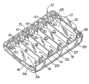
Referring now to the drawing and in
particular to Figures 1 through 5 there i8 shown
20 a one piece receptacle 10 for ret~ning and
dispensing a plurality o~ razor blade
cartridgQs. The receptacle 10 comprises a pair
of opposed end wallE~ 12 and 14, a pair of
opposed side walls 15 and 16, and a bottom wall
25 17. Dividing -~n~ in the form of a plurality
of separating walls 18, 19, 20 and 21 extend
between the opposed side walls 15 and 16 and
together with the end walls 12 and 14 form a
plurality of cavities 24, 25, 26, 27 and 28 each
30 of which are adapted to retain a razor blade
cartridge for att~t-' nt to a razor handle by
- the user.
As best shown in Figure 2 and
~ectional Figures 3, 4, and 5 each of the
cavities 24, 25, 26, 27 and 28 is provided with
rno~n~ for ret5~ n i ng a single razor blade
cartridge within the respective cavity, the
-
W096/03334 2 1 ~ 1 7 5 0 PCT~S9S/09168
cartridge being supported in spaced relation
with the end walls 12, 14, the side walls 15, 16
the bottom wall 17 and the separator walls 18,
19, 20 and 21. The retA~n~ng means i8
S ~ubstantially symmetrical within each of the
cavities 24, 25, 26, 27 and 28 and compri~es a
pai~ of u~wardly projecting ~oLL m~hQr~ 30
and 31 formed on the bottom wall 17 in each of
the re~pective cavities which are al o effective
to center a cartridge within its cavity.
Each of the cavities 24, 25, 26, 27
and 28 is further provided w$th a pair of
flanges 32, each having an edge connected to the
side wall 15 and bottom wall 17 and ext~n~i n~
inwardly into a respsctive cavity and a pair of
flanges 33 connected to the side wall 16 and
ext~n~ ng in an opposite direction into the
respective cavity. As best shown in Figure~ 4
and 5 each of the flanges 32 and 33 has an edge
connected to the bottom wall 17 a~ well a~
either the side wall 15 or 16 and ha~ a detent
35 or 36 di~posed adjacent the upper edge and
ext~n~ ng outwardly from a ~ur$ace of the flange
32 or 33 respectively. Betwaen each of the
flanges 32 or the flanges 33 a spacer element 38
or 39 is formed on the side wall 15 or 16
respectively and extends inwardly into the
cavity 24, 25, 26, 27 or 28 as is shown in
Figures 4 and 5.
It will be ~ot~d that each of th~
spacer element~ 38 and 39 ha~ an upper edge
which slants downwardly and inwardly into a
respective cavity for the purpo~e of guiding a
razor blade cartridge into the retA ~ n ~ ng
position. Each of the cavities 24, 25, 26, 27
and 28 is further provided with means for
guiding a razor blade cartridge into a
WO 96/03334 ~ 1 7 1 7 5 0 PCT/IIS95/09168
respecti~e ret~in~ng means in the form of guide
members 41 disposed adjacent the upper edge of
each of the separator walls 18, 19, 20 or 21 and
guide members 43 formed ad~acent the upper
surface of end wall 12, and guide members 44
disposed adjacent the upper edge, and on the.
inner surface of, end wall 14.
Referring now to Figures 6 through 12
and particularly to Figures 10 and 11, a razor
blade cartridge C i~ s~own as it is typically
ret~;ne~ in a ca~ity 24, 25, 26, 27, or in the
figures of the present drawing in cavity 28 in
Figure 10 or ca~ity 24 in Figure 11. In each
instance, the razor blade cartridge C is not
ret~i n~ by the receptacle walls but rather
within a cartridge ret~n~ng means formed by the
flanges 32 and 33 ha~ing detents 34 and 35 for
contacting the cartridge, supported against
sidewise movement by the spacer elements 38 and
39 and supported abo~e the bottom walls 17 by
the ~upport 1 `QrQ 30 and 31. Thus, it is
e~ident that the means.for ret~;ning the razor
blade cartridge C within a respecti~e ca~ty 24,
25, 26, 27 and 28 is independent of the walls of
the receptacl- 10 allow~ng the receptacle to be
n~factured of a material providing a ~igidity
suitable for mounting into a razor handle
support 8 shown in Figure 12, while maint~ n i n~
~he flexibility necessary to retain and dispense
a razor blade cartridge C.
As shown in Figure 12, the one piece
receptacle 10 may be ret~e~ on the under~ide
of a razor handle ~yG~ L member 50 as is
commonly practiced, the razor handle itself
being ret~;ne~ on the opposite side of the
support ~er by any --nQ (not shown) well
known in the art. In Figure 12, each of the
W096/03334 ~l 7t ~ 5a PCT~Sg5/09168
cartridges C have been removed from the
respective cavities 25, 26, 27 and 28 the
r~m~; n ~ ng cartridge being held in the retA~ n ~ n~
means of the cavity 24 and the receptacle 10
being fixed in a recessed portion of the support
member 50. The end wall 14 is slightly bowed
outwardly in the present configuration such that
it is a force fit within the cavity provided in
the support m~her 50.
In removing the cartridge C from the
receptacle 10 the razor handle R, as shown in
Figure 12, is attached to the razor blade
cartridge ~, generally by forcing the cartridge
receiving end of the handle onto the cartridge
with slight pressure, and the handle is merely
rocked back and forth to release the cartridge C
from the receptacle 10 in a manner as is
expl A; neA i n the aforementioned United StatQs
Patent 4,742,909.
From the foregoing it should be
evident that the present invention ~ one which
allows for the construction of a receptacle
whose walls are independently formed of a
riyidity to retain the shape and integrity of
the construction while the cartridge~ are held
in separate cartridge ret~ n ~ ng means which may
be designed of a flexibility to firmly retain
the cartridge within the receptacle and release
the cartridge from the receptacle for u~e, the
cartridge ret~ n i ng elements being independent
of the receptacle wall con~truction.