Note: Descriptions are shown in the official language in which they were submitted.
2171 11
- 1 -
RAMP DISCHARGE OUTLET AIR PRECLEANER
FIELD OF THE INVENTION
This invention relates generally to devices for
separating particulates from the air such as dirt, dust,
rain, and snow before they enter the air stream of an
engine, air compressor, or similar apparatus.
HACRGROUND OF THE INVENTION
Air precleaners are devices typically used in the
removal of dust, dirt, sand, rain, snow, and other airborne
l0 particulates in the air prior to the flow of air to the
carburetor of an internal combustion engine. Such
precleaners promote more efficient combustion and longer
engine and filter life. The efficiency of the precleaner
is determined by the percentage of particulates that are
removed from the intake air by the precleaner. The more
efficient the precleaner, the lesser the amount of
particulates that must be removed by the air filter.
The precleaners of the prior art have various
configurations that are employed as a means of removing the
particulates from the air. Examples of precleaners or
particle separators are shown in U.S. Pat. Nos. 2,193,479;
2,304,778; 2,417,130; 2,973,830; 3,552,102; 3,670,480;
3,740,932; 3,791,112; 3,973,937; 4,138,761; 4,197,102;
4,547,207; and 5,022,903.
CA 02171775 1998-O1-07
- 2 -
Although such precleaners may adequately perform
with respect to particulate removal, this is sometimes
accomplished at the expense of a reduced air flow, i.e.,
the precleaner itself may become an air restriction. Some
precleaners are also usable when positioned in only one
orientation.
Accordingly , a need has existed for an air
precleaner that efficiently removes particulates from the
air yet itself results in a minimal air restriction. What
is particularly needed is an air precleaner which is
capable of efficiently removing particulates from the air
without reintroducing the removed particulates into the
path of incoming air, thereby reducing efficiency and
restricting air flow.
SUMMARY OF THE INVENTION
In accordance with the present invention, an air
precleaner comprises:
(a) a base assembly having an inlet port through which
air enters the precleaner, an outlet port through which air exits
the precleaner, and a ramp coiled in a spiral around an outer
circumference of the base assembly and terminating in a discharge
port gap through which particulates exit the precleaner in a
generally tangential direction with respect to the outer
circumference of the base assembly;
(b) a preferably dome-shaped hood that defines an air
space above the base assembly so that the air space and the inlet
and outlet ports and the discharge port are in fluid communication,
the hood positioned above the base so as to enclose the discharge
ramp; and
(c) a rotor assembly that is rotatably mounted within
the air space that is defined by the hood and that rotates when air
enters through the inlet port to fling particulates outward toward
the hood and downwardly toward and along the ramp for expulsion
through the discharge port gap, wherein the rotor assembly further
includes,
CA 02171775 1998-O1-07
- 2a -
an axle mounted to the base assembly,
a hub that is rotatably mounted upon the axle,
and
an arm that is attached to the hub in the path of air
entering through the inlet port, the air causing the hub to rotate
upon the axle and the arm to fling particulates outward, wherein the
arm includes at least an axial blade that is in a plane which
intersects along the axis of rotation of the hub.
In a preferred embodiment, the base assembly has an inner
circumferential wall and an outer circumferential wall, the inner
circumferential wall defining an air outlet port, and the outer
circumferential wall defining the inner circumeference of the
discharge port ramp. Angled web supports connect the outer
circumferential wall to the inner circumferential wall and their
arrangement forms air inlet ports that direct air upon the rotor
assembly. The rotor assembly hub has a plurality of arms extending
therefrom that rotate upon the axle when struck by air entering
through the inlet ports. Each arm preferably includes two blades
oriented perpendicularly to one another: a first blade in a plane
radial to the hub, i.e., a plane perpendicular to the axis of
rotation, and a second blade in a plane axial to the hub,
i.e., a plane parallel to and preferably coincident
CA 02171775 1998-O1-07
- 3 -
with the axis of rotation. The first blade preferably
extends perpendicularly from the front side of the second
blade in a direction corresponding to the direction of
rotation of the rotor assembly; for example, if the rotor
assembly is to rotate in a counterclockwise direction, the
first blade will extend from the second blade in a
counterclockwise direction. The backside of the second
blade does not have a blade or airfoil extending from it,
so that air flowing past the backside of the second blade
is substan~ial~y.unobstructed.
Preferably, the discharge port ramp winds around the
outer cirumference of the outer circumferential wall of the base
assembly in the same direction as the rotation of the rotor assembly
and starting at the top of the outer circumferential wall, the ramp
terminates in a gap at the bottom of the wall below its starting
point, approximately 360 degrees removed. The starting and terminal
ends of the discharge port ramp define respectively the top and
bottom of the particulate discharge port itself.
In the operation of the air precleaner of the
present invention, air to be cleaned is drawn through the
air inlet ports and directed toward the rotor assembly.
Air incident upon the arms of the rotor assembly causes
rotation of the rotor assembly, so that particulate matter
is flung toward the hood. The arms of the rotor preferably
each have a large surface area panel integrally formed at
the outer most end of each arm to increase the amount of
inertia of the rotor and provide enhanced particulate
sweeping action at the radial periphery of the rotor. The
panels preferably lie in an axial plane. The rotor
preferably also includes a tab on each arm which extends
downwardly from the second blade at a position adjacent to
the hub. The tabs, which can generally lie in, or be bent
backwardly from, an axial plane, can be sized to provide
control of the typical rotational speed of the rotor.
These tabs extend down into the throat of the air outlet
port.
217115
- 4 -
Particulates are driven by the rotor out to the
hood and then down the inner surface of the hood to be
discharged through the ramp discharge port and exit through
the gap. The spiral shaped discharge path creates
significant velocity for the particulates. The
particulates are thus rapidly drawn to the ramp discharge
port, located beyond the periphery of the air inlet ports,
and thus out of the path of incoming air. Cleaned air is
drawn through the air outlet port by for example, the
vacuum draw of an engine to which the air precleaner is
attached.
The precleaner of the present invention provides
restriction of the air entering and exiting the precleaner
which is generally as low as or less than existing
precleaners, thus allowing complete and efficient
combustion of the fuel. Nonetheless, the precleaner
concurrently provides more efficient removal of
particulates than existing precleaners.
Further objects, features, and advantages of the
invention will be apparent from the following detailed
description when taken in conjunction with the accompanying
drawings.
BRIEF DESCRIPTION OF THE DRAWINGS
In the drawings:
Fig. 1 is a side view of the air precleaner of
the present invention.
Fig. 2 is a perspective view of the air
precleaner of the present invention with portions of the
hood of the precleaner being cut away to show internal
parts of the precleaner.
Fig. 3 is a perspective view of the base assembly
of the air precleaner of the invention.
Figs. 4-7 are a series of side views of the base
assembly of the air precleaner of the invention, showing
2111775
- 5 -
the spiral of the ramp discharge port at various rotations
of the base assembly.
DETAILED DESCRIPTION OF THE INVENTION
With reference to the drawings, Figs. 1 and 2
show various views of the air precleaner of the present
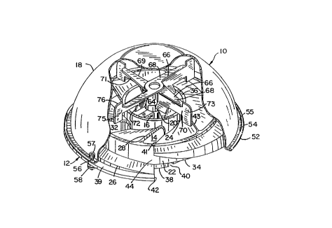
invention generally at 10. The air precleaner l0 comprises
a base assembly 12 having air inlet ports 14 and an air
outlet port 16, a hood 18 positioned above the base
assembly 12, and a rotor assembly 20 that is rotatably
mounted on the interior of the precleaner 10. The
precleaner 10 is a device used for separating particulates
from a carrier fluid. Where the carrier fluid is air,
exemplary particulates include dust, dirt, sand, rain,
snow, or any other airborne particulate matter.
The base assembly 12, best shown in Fig. 3, is
cast or formed in a single piece to include an outer
circumferential wall 22, an inner circumferential wall 24,
a plurality of web segments 28, a strut 30, and an outlet
port ramp 26. In the orientation shown in the figures, the
outer circumferential wall 22 has a top 32 and a bottom 34.
The inner circumferential wall 24 has a top 36 and a bottom
38. A peripheral ledge 39 extends from the bottom 34 of
the outer circumferential wall 22 to beyond the discharge
port ramp 26. The peripheral ledge 39 may entirely circle
the base 12 or may contain a gap 42 which corresponds to a
discharge port gap 44. The web segments 28 connect the
outer circumferential wall 22 to the inner circumferential
wall 24 and, by their arrangement between the outer and
inner circumferential walls 22 and 24, form the air inlet
ports 14 that allow fluid communication from the exterior
of the precleaner 10 to the interior of the precleaner 10.
In the orientation shown in Figs. 2 and 3, each of the web
supports is angled from a low first edge 41 to a high
second edge 43, the second edge 43 being located
counterclockwise from the first edge 41. The web supports
CA 02171775 1998-O1-07
- 6 -
28 are thus successively arranged in counterclockwise
fashion in the area formed between the outer
circumferential wall 22 and the inner circumferential wall
24. each of the air inlet ports 14 is formed and bounded
by the second edge 43 of one web support 28 and the first
edge 41 of the succeeding counterclockwise web support 28.
The air inlet ports 14 are also bounded by the outer
circumferential wall 22 and the inner circumferential wall
24. There are six air inlet ports 14 in the precleaner 10
as depicted in Fig. 3, although other numbers are possible.
The ports 14 are angled so that fluid is drawn in from the
exterior of the precleaner 10 and directed at the rotor
assembly 20, in a manner described below.
The inner circumferential wall 24 defines the air
outlet port 16, with the bottom 38 of the inner
circumferential wall 24 extending below the bottom 34 of
the outer circumferential wall 22. The outlet port 16, as
defined by the inner circumferential wa,l1 24, is typically
serially connected and fitted to the air intake of an
engine, air compressor, or similar apparatus, so that the
precleaner 10 acts to pre-clean the air prior to its entry
to the apparatus. The operation of the precleaner 10 will
be described in further detail below. The inner
circumferential wall 24 preferably has longitudinal slots
40 that extend upward from the bottom 38 of the inner
circumferential wall 24 so that the inner circumferential
wall 24 may be more easily fitted over the top of the air
intake of the engine, air compressor, or similar apparatus.
For operational use a clamp or band is preferably wrapped
circumferentially about the inner circumferential wall 24
in the region of the longitudinal slots 40 so as to tightly
secure the inner circumferential wall about the air intake
of the engine, air compressor, or similar apparatus. The
outlet port 16 of the precleaner 10 is therefore in fluid
communication with the air intake of the engine, air
compressor, or similar apparatus. The strut 30, upon which
2~li;~i'S
_ 7 _
the rotor assembly 20 is mounted, extends diametrically
across the outlet port 16.
The hood 18 preferably has a dome shaped surface
51, terminating at a peripheral edge 52. "Dome shaped", as
used herein, is defined to mean a shape that is
hemispherical, convex, shaped like an inverted bowl, or to
have portions that are represented by sections that are
substantially hemispherical, convex, or shaped like an
inverted bowl. The outer walls of the dome shaped hood 18
may also be cylindrical rather than continuously curved.
The hood 18 encloses the entire upper surface of the base
assembly 12, including the discharge ramp 26, and defines
an air space above the base assembly 12 so that the air
space and the inlet and outlet ports 14 and 16 and the
discharge port gap 44 are in fluid communication. The
peripheral edge 52 is preferably rolled to form a lip 54
and a circumferential channel 55 between the lip 54 and the
domed surface 51. The hood 18 may then be attached to the
base assembly 12 by bolts 56 that extend through the
peripheral edge 52 and the ledge 39 of the base assembly
12, the bolts 56 each having heads at one end 57 that fit
within the channel 55 to prevent rotation of the bolts.
The bolts 56 are secured by nuts 58 at the end of the bolts
56 opposite the heads 57.
The rotor assembly 20 comprises a machined hub 64
with four arms 66 extending radially therefrom, the arms 66
being equal distant from each other to form an "x"-type
configuration. It is also possible that more or less than
four arms 66 could be used. Each of the arms has a first
blade 68 and a second blade 70. The first blades 68 are in
a plane radial to the hub 64, that is, a plane
perpendicular to the axis of rotation of the rotor; the
second blades 70 are preferably in planes axial to the hub
64, that is, planes parallel to and preferably coincident
with the axis of rotation. The first blade 68 has a
leading edge 71 and a trailing edge 69, wherein the leading
edge 71 precedes the trailing edge 69 as each arm 66 moves
2~7i ~l
_8_
along its circular path of rotation. The first blade 68 is
preferably wedge shaped, being widest at the position at
which it joins the hub 64 and tapering to a terminus of the
leading edge 71 at a position adjacent to paddles 73 formed
at the outer ends of the arms. The second blade 70
descends preferably perpendicularly from the trailing edge
of the first blade 68 and has a front side 75 and a back
side 76. In a base assembly 12 that is designed to create
a counterclockwise rotor assembly 20 rotation (as in the
base assembly shown in Figs. 2 and 3), the first blade 68
protrudes from the front side of the second blade 70 in a
counterclockwise direction, whereas the backside 76 of the
second blade 70 is free of obstruction, and thus air
flowing past the back side 76 is substantially
unobstructed.
Each of the arms 66 also preferably has an
integrally formed tab 72 that extends downwardly from the
axial blade 70 in a manner as depicted in Fig. 2. The tabs
72 extend downwardly into the throat of the air outlet port
16. The tabs 72 are located proximate the hub 64 and are
slightly bent or flared in a clockwise direction. The tabs
72 may also extend downwardly from the axial blade 70 in
the axial plane, i.e., without a bend. A bent tab can be
advantageous at high altitudes, where the angle of the tabs
72 may be increased to compensate for the lower intake air
pressure and thereby maintain the rotational speed of the
rotor assembly 20 at a desired high rate despite the low
air density. It may be desirable, and is considered within
the scope of the present invention, for the length of the
tabs 72 to be selected for different applications. The
size of the tabs 72 is related to the speed of the rotor
assembly 20, which correspondingly affects the efficiency
of the precleaner 10 for different altitudes of operation.
In higher altitude applications, for example, longer tabs
72 are preferable.
Each of the arms 66 further preferably includes a
paddle 73 extending from the outer end of the second blade
CA 02171775 1998-O1-07
_ g _
70. The paddle 73 provides increased surface area to meet
the air drawn in from the air inlet ports 14, and thereby
better utilize the force of the inlet airflow, and can help
increase the rotational speed of the rotor assembly 20 and
impel particulates toward the inner surface of the hood 12.
The paddles 73 also add mass to each of the arms 66 and
thereby increase the moment of inertia of the rotor
assembly, helping to maintain a uniform rotational speed of
the rotor assembly 20. An increased moment of inertia
could also be obtained by replacing the paddles 73 with
weights located on the ends of each rotor arm 66.
However, the planar paddles 73 are preferred. While the
paddles 73 may be placed anywhere along the second blade
70, greater rotational speed and a greater moment of
inertia are obtained when the paddle 73 is located further
from the hub 64. The paddles preferably have substantially
larger axial dimension or "height" than the second blades
70, extending above and below the second blades as shown in
Fig. 2.
The hub 64 is preferably mounted upon a precision
ground axle by two highly ground precision shielded
bearings (not shown). The axle is threaded at one end and
is attached to the strut 30 that extends diametrically
across the outlet port 16 by a nut (not shown).
The discharge port ramp 26, as shown in Figs. 4-7
from several rotational angles, has an upper surface 80, a
starting end 82 and a terminal end 84. The ramp 26 extends
radially from the outer surface 86 of the outer
circumferential wall 22 to the inner surface of the hood 18
and circumferentially around the outer circumferential wall
22. The upper surface of the ramp 80 is everywhere
approximately perpendicular to the outer surface 86 of the
outer circumferential wall 22. At the starting end of the
ramp 82 the upper surface of the ramp 80 is approximately
adjacent to the top 32 of the outer circumferential wall
22. As the surface of the ramp 80 winds around the outer
circumferential wall 22 the surface 80 spirals downward
~1~~ %~5
- 10 -
toward the bottom 34 of the outer circumferential wall 22.
At the terminal end 84 of the ramp the upper surface of the
ramp 80 is approximately adjacent to the bottom 34 of the
outer circumferential wall 22. The starting end of the
ramp surface 82 is preferably located in approximately the
same axial plane as the terminal end of the ramp surface
84, such that the ramp surface 80 creates an approximately
360 degree spiral between the outer surface 86 of the outer
circumferential wall 22 and the inner surface of the hood
18. The ramp spirals downwardly in the same direction as
the direction of rotation of the rotor arms so that
particulates swirling downwardly along the inner surface of
the hood continue their motion smoothly into the ramp
region.
The discharge port gap 44 is bounded on the top
by the starting end of the ramp 82, on the bottom by the
terminal end of the ramp 84, and on the sides by the outer
surface 86 of the outer circumferential wall 22, and the
inner surface of the hood 18. As is shown in Fig. 4 an
exhaust area 88 is created by removing a portion of the
ramp 26 immediately adjacent to the discharge port gap 44
and below the starting end of the ramp 82. The exact size
and shape of this exhaust area 88 is not significant, but
the exhaust area should be sufficiently large to allow for
particulates which have been removed from the air by the
air precleaner to be freely discharged from the discharge
port 44.
Because the spiraled surface of the ramp 80
increases the efficiency of the discharging of particulates
by the air precleaner 10, a ramp in the form of a
substantially two dimensional strip extending radially
perpendicular to the outer surface 86 of the outer
circumferential wall 22 and coiled in a spiral around the
outer circumferential wall 22 between its outer surface 86
and the inner surface of the hood 18 may also be utilized
rather than a ramp cast integrally with the rest of the
base. If a coiled shelf is used instead of the integral
21 l l X75
- 11 -
ramp configuration shown, the mass of the casting forming
the base 12 may be reduced and no machining of the ramp
surfaces would be required.
In the operation of the precleaner 10, air that
may contain particulate matter is typically drawn into the
precleaner by vacuum pressure caused by an engine or
similar device mounted below the air outlet port 16 of the
precleaner 10. The air is thus drawn through the air inlet
ports 14, the angling of the web supports 28 directing the
air flow in a circular, counterclockwise direction within
the precleaner 10. The airflow is directed against the
blades 68 and 70, and the tabs 72, of the rotor assembly
20, thus causing the rotor assembly 20 to spin in a
counterclockwise direction. Of course, the direction of
the web supports 28 could be reversed, and the orientation
of the parts of the rotor assembly 20 reversed, to provide
rotation in the clockwise direction. If such were the
case, the direction of the discharge ramp 26 spiral would
also b~ reversed. The circular motion of the rotor
assembly 20 impels the intake air into a circular motion,
causing a centrifugal force to be exerted on particulates
within the air that has been drawn into the precleaner 10.
The particulates are thus flung outwardly against the hood
18. The configuration of the hood 18 forces particulates
down the interior of the hood surface toward the upper
surface 80 of the discharge ramp 26. The upper surface 80
of the ramp 26 creates a spiral path toward the discharge
port gap 44. This spiral creates significant velocity in
the particulates being discharged, thereby rapidly removing
them out of the path of incoming air from the air inlet
ports 14, and discharging them out of the air precleaner 10
through the discharge port 40 in a direction generally
downwardly and tangential to the circumference of the air
precleaner. The approximately 360 degree full spiral of
the ramp surface 80 has been found to increase the
efficiency of the air precleaner 10 over those having
discharge ports of conventional designs, e.g., a discharge
CA 02171775 1998-O1-07
- 12 -
gap which extends partially or entirely around the
periphery of the precleaner at the same level. The air
cleaned by the air precleaner 10 is then drawn by the
vacuum effect of the engine through the air outlet port 16
into the intake of an engine or a similar apparatus. A
partial ramp, i.e., one less than 360° would generally not
be as effective in generating a high discharge velocity as
the full spiral, and thus a substantially full spiral is
preferred although some advantage may be obtained with less
than a 360° spiral.
The above described precleaner of the present
invention is an effective means of pre-cleaning air that is
to be introduced into an engine, air compressor, or similar
apparatus, and is.efficient even at high altitudes. It is
to be understood that the precleaner 10 of the present
invention is not limited merely to applications within air
and to those applications that remove particles that are
typically contained within air. The precleaner 10 will
work in applications involving other fluids as well.
Though the figures and the corresponding text have for
example assigned a "top" a "bottom", and corresponding
identifying labels to the precleaner 10, these have been
used for illustrative purposes inasmuch as the air
precleaner can be mounted and will function in any
position. Further, though the air inlet ports 14, the
rotor assembly 20, and the discharge ramp have been
depicted to cause air flow and rotation of the rotor
assembly 20 and particulate discharge in a counterclockwise
direction, a precleaner with air flow and rotation of the '
rotor assembly and discharge of particles in a clockwise
direction is, as noted above, within the scope of the
present invention.
It is further understood that the invention is
not confined to the particular construction and arrangement
of parts herein illustrated and described, but embraces
such modified forms thereof as come within the scope of the
following claims.