Language selection

Search

Patent 2172093 Summary

Third-party information liability

Some of the information on this Web page has been provided by external sources. The Government of Canada is not responsible for the accuracy, reliability or currency of the information supplied by external sources. Users wishing to rely upon this information should consult directly with the source of the information. Content provided by external sources is not subject to official languages, privacy and accessibility requirements.

Claims and Abstract availability

Any discrepancies in the text and image of the Claims and Abstract are due to differing posting times. Text of the Claims and Abstract are posted:

  • At the time the application is open to public inspection;
  • At the time of issue of the patent (grant).
(12) Patent: (11) CA 2172093
(54) English Title: OBSERVATION PLATFORM
(54) French Title: PLATE-FORME D'OBSERVATION
Status: Deemed expired
Bibliographic Data
Abstracts

English Abstract


A portable collapsible platform having a platform, with a
mounting edge, a support frame swingably mounted to the
mounting edge of the platform and being swingable between
a more or less nested portable position closely adjacent
the platform, and an extended more or less vertical
position, attachments for attaching the support frame to
a structure above the ground, braces extending between
the support frame and the platform to hold the platform,
when it is extended, generally horizontal, and, teeth on
the mounting edge of the platform, for engaging the
structure.


French Abstract

Cette invention concerne une plate-forme mobile repliable composée d'un plateau, d'une rive d'accrochage, d'un bâti pivotant articulé à la rive d'accrochage pouvant occuper, en cours de transport, une première position plus ou moins rabattue à proximité immédiate du plateau et, en service, une position dépliée plus ou moins verticale, de fixations servant à rendre le bâti solidaire d'une structure surélevée, d'étais entre le bâti et le plateau, étais dont la fonction est de maintenir ce dernier dans une position généralement horizontale, et de pointes sur la rive d'accrochage servant à prendre prise sur la structure.

Claims

Note: Claims are shown in the official language in which they were submitted.


The embodiments of the invention in which an exclusive property or priviledge
is
claimed are defined as follows:
1. A portable collapsible seating and storage platform comprising;
a generally planar platform, having an upper and underside;
a mounting edge plate extending along and defining one edge of said platform
and extending form one side to the other of said platform;
a free edge of said platform spaced from said mounting edge plate, said
platform providing a planar surface extending from said mounting edge plate to
said
free edge;
a pair of L shaped angle bars extending parallel to one another along either
side
of said platform and extending alongside each end of said mounting edge plate;
attachment flanges secured to said angle bars at each end of said mounting
edge plate;
a support frame comprising two linear frame bars defining lower and upper
ends,
said lower ends being swingably mounted to said attachment flanges at each end
of
said mounting edge plate of said platform said linear frame bars extending
from said
attachment flanges and being angled towards one another to form a generally A
shaped frame, said linear frame bars being joined together at their upper ends
at the
apex of said A shape and being swingable between a more or less nested
position
closely adjacent the platform, and an extended more or less vertical position
at right
angles to said platform for lying directly against the surface of a structure
means;
attachment means for attaching said support frame lying against the surface of
7


the structure means above the ground;
a cross bar extending between said linear frame bars intermediate their lower
and upper ends;
a seat frame of generally truncated triangular shape having two angled side
frame portions attached to said attachment flanges on said mounting edge plate
and
angled towards one another;
a junction bar portion of said seat frame extending between said side frame
portions remote from said attachment flanges;
a flexible seat secured between said cross bar of said support frame and said
junction bar portion of said seat frame and providing secure seating for a
person;
flexible strain elements secured to each end of said cross bar of said support
frame
and being secured to said parallel L shaped angle bars of said platform
intermediate
said mounting edge plate and said free edge of said platform whereby to hold
said
platform, when extended relative to said support frame, with said platform
generally
horizontal, and,
structure engaging teeth means forming a concave arcuate curve in said
mounting edge plate of said platform and extending rearwardly of said
platform, for
engaging said structure.
2. A platform as claimed in Claim1 and including collapsible container means
secured to said seat.
8

Description

Note: Descriptions are shown in the official language in which they were submitted.


zmz~~~
FIELD OF THE INVENTION
s.
The invention relates to a portable collapsible
observation platform, and in particular, to such a
platform which can be erected at various positions in a
tree or on a post.
BACKGROUND OF THE INVENTION
The provision of an observation platform in wooded
areas is desirable for various purposes such as bird
watching, hunting, and the like. Permanent platforms
have been available which can be permanently erected in a
position in a tree, but generally speaking they are bulky
and cumbersome, and cannot readily be moved from place to
place. Platforms are also required for working at an
elevation such as up a post or on the side of a
structure, or indoors in some cases.
Portable platforms such as have been proposed in the
past have suffered from numerous disadvantages. In many
cases, they are poorly designed and will not support a
great deal of weight. In other cases, movement on the
platform will cause the platform to swing uncontrollably,
causing a person to fall.
For the sake of simplicity , in this text all such
different above ground locations will be referred to by
the generic term "structure", which is intended to
include every type of elevated location to which the
platform can be attached.
-1-

BRIEF SUN~IARY OF THE INVENTION
It is, therefore, with a view to overcoming these
various disadvantages that the invention provides a
portable collapsible platform comprising a generally
planar platform, having an upper and underside, and a
mounting edge and a free edge, a support frame swingably
mounted to said support edge of said platform and being
swingable between a more or less nested portable position
closely adjacent the platform, and an extended more or
less vertical support position, attachment means for
attaching said support frame to structure located above
the ground, bracing means extending between said support
frame and said platform whereby to hold the same when
extended in a generally normal relation with said
platform generally horizontal, and, structure engaging
teeth means on said mounting edge of said platform, for
engaging said post.
The invention also provides a foldable and nestable
seat. The seat can comprise a sub-frame of generally
triangular shape having two angled side portions attached
to said platform, and a junction portion extending
between said side portions remote from said platform, and
a flexible seat adapted to extend from said support frame
to said junction portion, when extended, said seat
providing a secure seat for a person.
The invention also comprises a support frame which
is of triangular shape having two side portions having
lower and upper ends, the lower ends being connected to
-2-


opposite ends of the mounting edge of the platform and
the upper ends being joined together and having a bracing
portion extending transversely between them more or less
in the form of a letter A.
The flexible seat may be connected between the
transverse bracing portion, and the junction portion of
the seating frame.
The various features of novelty which characterize
the invention are pointed out with more particularity in
the claims annexed to and forming a part of this
disclosure. For a better understanding of the invention,
its operating advantages and specific objects attained by
its use, reference should be had to the accompanying
drawings and descriptive matter in which there are
illustrated and described preferred embodiments of the
invention.
IN THE DRAWINGS
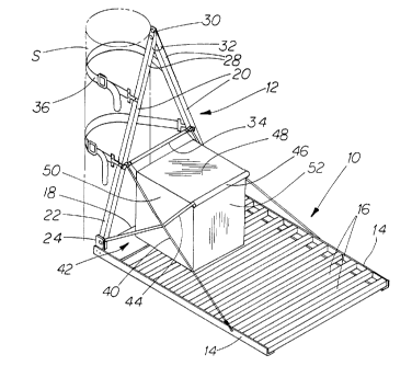
Figure 1 is a perspective illustration of a portable
collapsible platform illustrating the features of the
invention;
Figure 2 is a side elevational view of the platform
of Figure 1, shown erected;
Figure 3 is a side elevational view corresponding to
Figure 2 showing the platform collapsed and nested ready
for carrying, and,
Figure 4 is an enlarged detail of the mounting edge
of the platform portion and showing the teeth.
-3-


CA 02172093 2000-02-16
DESCRIPTION OF A SPECIFIC EMBODIMENT
The various features of the invention are illustrated in the drawings, which
are
shown here by way of example only and without limitation. In Figure 1 it will
be
seen that the platform there is shown as having a platform portion indicated
generally
as 10, and a support A-frame portion indicated generally as 12. The planar
portion 10
consists of side frames 14 of linear L-shaped angle metal parallel to one
another and
spaced apart cross members 16, all preferably formed of lightweight metal and
has a
mounting edge plate 18 extending from one side frame to the other. The support
A-
frame is also formed of light weight metal and comprises two linear side frame
bar
members 20 - 20, having lower and upper ends, the lower ends 22 being attached
to
flanges 24 on either side of the platform, on opposite ends of the mounting
edge 18 of
the platform.
The upper ends 28 of the side frames 20 are angled inward and connected
together as at 30, and preferably in this case incorporate suspension means
such as a
U-bolt 32.
A transverse cross bar 34 extends between the side frames making the shape
of a letter A.
The support frame can be swung on bolts 26 relative to the platform as shown
in Figures 2 and 3.
2 0 Attachment means in the form of straps 36 are connected to the side
frames,
and may be of sufficient length so that they can be wrapped around a structure
S such
as a post or tree trunk at a suitable height and hold the platform in
position. The
-4-


CA 02172093 2000-02-16
mounting edge plate 18 has teeth 38 for engaging the post or tree trunk or
other
structure, to prevent the platform from swinging after it has been attached.
The teeth
38 of the mounting edge plate 18 are formed in a generally concave arcuate
shape so
as to conform to the curvature as a structure S such as a tree trunk or the
like.
Strain elements are provided in the form of flexible wires 40 extending
between the ends of the transverse cross bar 34, and a point midway along the
side
frames 20-20 of the platform.
In this way, when the platform is extended, it is securely held in a more or
less
level position relative to the support frame.
In order to provide a seat, there is advantageously provided a seating frame
42
having two side members 44, the lower ends of which are connected to bolts 26
,
connecting through flanges 24 at opposite ends of the mounting edge plate 18
of the
platform 10.
The two side members 44 are more or less angled towards one another and
meet at a junction portion 46 . A seat 48 is preferably formed of flexible
material
such as canvas and is secured by loops, connected respectively to the
transverse cross
bar 34 and the junction portion 46. A person can thus sit on the seat and will
be
securely supported.
If desired, a container 50 can be fitted beneath the seat. The container 50
will
2 0 also be formed of flexible material such as canvas, and may have an end
opening or
flap 52 which may be closed by any suitable means such as a slide fastener
(not
shown).
-5-


CA 02172093 2000-02-16
The operation of the invention is self evident from the foregoing description.
It is light weight and it may readily be carried about in folded or collapsed
portable
condition. It may easily be opened up and erected in woodlands, for
observation, or
for example on a post where it is desired to do work or at any other location
where
structure as defined herein is to be found. The platform when folded is
compact and
can be stored or placed in a vehicle, and can easily be moved around.
The foregoing is a description of a preferred embodiment of the
invention which is given here by way of example only. The invention is not to
be
taken as limited to any of the specific features as described, but comprehends
all such
variations thereof as come within the scope of the appended claims.
-6-

Representative Drawing
A single figure which represents the drawing illustrating the invention.
Administrative Status

For a clearer understanding of the status of the application/patent presented on this page, the site Disclaimer , as well as the definitions for Patent , Administrative Status , Maintenance Fee  and Payment History  should be consulted.

Administrative Status

Title Date
Forecasted Issue Date 2001-11-27
(22) Filed 1996-03-19
(41) Open to Public Inspection 1997-09-20
Examination Requested 1998-01-30
(45) Issued 2001-11-27
Deemed Expired 2012-03-19

Abandonment History

Abandonment Date Reason Reinstatement Date
2001-04-30 FAILURE TO PAY FINAL FEE 2001-07-27

Payment History

Fee Type Anniversary Year Due Date Amount Paid Paid Date
Application Fee $0.00 1996-03-19
Request for Examination $200.00 1998-01-30
Maintenance Fee - Application - New Act 2 1998-03-19 $50.00 1998-03-06
Maintenance Fee - Application - New Act 3 1999-03-19 $50.00 1999-03-10
Maintenance Fee - Application - New Act 4 2000-03-20 $50.00 2000-03-10
Maintenance Fee - Application - New Act 5 2001-03-19 $75.00 2001-03-02
Reinstatement - Failure to pay final fee $200.00 2001-07-27
Final Fee $150.00 2001-07-27
Maintenance Fee - Patent - New Act 6 2002-03-19 $75.00 2002-02-28
Maintenance Fee - Patent - New Act 7 2003-03-19 $75.00 2003-02-25
Maintenance Fee - Patent - New Act 8 2004-03-19 $100.00 2004-03-15
Maintenance Fee - Patent - New Act 9 2005-03-21 $100.00 2005-03-08
Maintenance Fee - Patent - New Act 10 2006-03-20 $125.00 2006-02-08
Maintenance Fee - Patent - New Act 11 2007-03-19 $125.00 2007-01-31
Maintenance Fee - Patent - New Act 12 2008-03-19 $125.00 2008-01-22
Maintenance Fee - Patent - New Act 13 2009-03-19 $125.00 2009-01-28
Maintenance Fee - Patent - New Act 14 2010-03-19 $125.00 2010-01-18
Owners on Record

Note: Records showing the ownership history in alphabetical order.

Current Owners on Record
ARCURI, NATALE
Past Owners on Record
None
Past Owners that do not appear in the "Owners on Record" listing will appear in other documentation within the application.
Documents

To view selected files, please enter reCAPTCHA code :


To view images, click a link in the Document Description column. To download the documents, select one or more checkboxes in the first column and then click the "Download Selected in PDF format (Zip Archive)" or the "Download Selected as Single PDF" button.

List of published and non-published patent-specific documents on the CPD .

If you have any difficulty accessing content, you can call the Client Service Centre at 1-866-997-1936 or send them an e-mail at CIPO Client Service Centre.


Document
Description 
Date
(yyyy-mm-dd) 
Number of pages   Size of Image (KB) 
Cover Page 2000-12-11 1 48
Claims 2000-02-16 2 74
Description 1996-06-21 6 197
Representative Drawing 2001-10-24 1 22
Description 2000-02-16 6 200
Cover Page 1997-10-28 1 48
Representative Drawing 2000-12-11 1 15
Cover Page 1996-06-21 1 14
Abstract 1996-06-21 1 17
Claims 2000-07-28 2 75
Claims 1996-06-21 3 76
Drawings 1996-06-21 1 48
Cover Page 2001-10-24 1 47
Representative Drawing 1997-10-28 1 15
Prosecution-Amendment 2000-07-28 5 153
Fees 2000-03-10 1 31
Fees 2003-02-25 1 33
Fees 2002-02-28 1 36
Prosecution-Amendment 2000-04-04 1 26
Prosecution-Amendment 2001-07-27 1 41
Prosecution-Amendment 2001-09-19 1 14
Prosecution-Amendment 1998-05-07 4 120
Assignment 1996-03-19 3 131
Prosecution-Amendment 1998-01-30 1 34
Fees 2001-03-02 1 29
Fees 1999-03-10 1 36
Prosecution-Amendment 1999-08-24 2 4
Prosecution-Amendment 2000-02-16 7 220
Fees 1998-03-06 1 34
Fees 2004-03-15 1 32
Correspondence 2004-03-15 2 62
Correspondence 2004-04-13 1 13
Correspondence 2004-04-13 1 16
Correspondence 2005-03-08 1 26
Correspondence 2005-03-18 1 13
Correspondence 2005-03-18 1 16
Correspondence 2005-05-25 1 13
Fees 2005-03-08 1 65
Fees 2006-02-08 1 46
Prosecution Correspondence 2000-08-03 4 109
Prosecution Correspondence 2000-07-28 5 169
Fees 2007-01-31 1 75
Fees 2008-01-21 1 45
Fees 2009-01-28 1 47
Fees 2010-01-28 3 158