Note: Descriptions are shown in the official language in which they were submitted.
2172~8
wHIpp~n CR~M DISPFNSER
R~CKGROUND OF THE INVENTION
This invention relates to whipped cream dispensers. More
specifically, this invention relates to a whipped cream dis-
penser comprising an aerosol-type container having a discharge
valve which is opened by tilting the valve spout, and it in-
cludes means to limit the tilting of the spout and relieving
stress on the stem.
Since at least the 1950's there have been patents disclos-
ing pressurized containers for whipped cream in which a flexible
spout is mounted in the opening of the container. The spout
receives the stem of a relatively rigid valve element which
terminates downwardly in a valve head normally seating in the
inlet of the spout. In operation, the container is inverted and
the spout is tipped causing the stem to unseat the valve head,
permitting discharge. The stem often includes a deflector for
assisting in foaming and guiding the fluid to an expansion
chamber in the spout and frequently the upper end of the spout
(15-S)
7 ~
has inwardly curving petals presenting a "tulip" top to focus the
discharge and reduce spattering.
Examples of such structure are:
U. S . 2,957,610 Michel U.S. 3,722,760 Hug
U. S . 2,975,944 Michel U.S. 3,758,007 Rosen
U. S . 2,992,760 Turk U.S. 4,958,755 Gerstung
The above described arrangement in more or less similar
embodiments has been used for years. At the same time, aerosol
valves typified by structures used in dispensing hair spray and
deodorants have taken a different form wherein a plastic valve body
is mounted in a pedestal on a metal mounting cup, the valve body
containing a tilt-type valve element having a tubular stem extending
upwardly through a sealing gasket and an opening in the mounting cup.
Such structures are typified by the old U.S. Briechle patent
153,158,298 issued November 24, 1964.
It has been found relatively recently that tilt-type aerosol
valves can be used for whipped cream provided they are fitted with
a whipped cream actuator spout which telescopes onto the tubular
valve stem. The actuator has contained a stationary deflector
20 element and has been formed with a tulip upper end.
~ 2
,~.
2~72~
One of the serious drawbacks of earlier embodiments of
whipped cream dispensers using tilt-type aerosol valves de-
scribed above has been stem breakage. Inherent in the use of
the actuator as an extension of the aerosol stem is that consid-
erable leverage is developed which places an inordinant stress
on the fragile stem. Such stems usually of plastic such as an
acetal have an outside diameter of .155" with a wall thickness
of only .018 inch. As a result, whipped cream dispensers using
tilt-type valves have failed, snapping off at the stem just
above the gasket.
It is an object of the present invention to limit the
tilting of the discharge actuator and reduce the stress on the
stem in such a combination. The limit is effected by asserting
a positive stop relationship between the actuator and the metal
pedestal of the mounting cup.
SUMMARY OF THE INVENTION
Therefore, the invention in such a tilt-type whipped cream
dispenser incorporating a tilt-type aerosol valve is the im-
provement wherein the tubular actuator has at its base a down-
(15-S) 3
2~720~8
wardly facing annular shoulder. This shoulder, upon butting
against the metal of the valve pedestal, prevents further
tilting and further stress on the tubular valve stem. Further,
the improvement includes retaining means to keep the actuator in
proper "home" position on the valve stem, precluding any upward
"creeping" of the actuator with respect to the stem which would
increase the distance of the shoulder from the mounting cup and
defeat the stop action. In the preferred embodiment the retain-
ing means includes an outward peripheral rib on the stem and an
inward rib on the actuator which, in installation, snap past
each other immediately proximate the "home" position.
BRIEF DESCRIPTION OF THE DRAWINGS
Further objects and features of the invention will be
apparent to those skilled in the art from a study of the follow-
ing specification and the accompanying drawings, all of which
disclose a non-limiting embodiment of the invention. In the
drawings:
Fig. l is an elevational view partly in section taken on
the center line of the dispensing assembly including the tilt-
(15-S) 4
~17~Q~8
'
type aerosol valve and the tubular whipped cream actuator, both
shown in tilted condition;
Fig. 2 is a greatly enlarged view of a portion of Fig. l
showing the retaining means for the actuator; and
Fig. 3 is a sectional view taken on the line 3-3 of Fig. l.
DESCRIPTION OF T~ PREFERRED EMBODIMENT
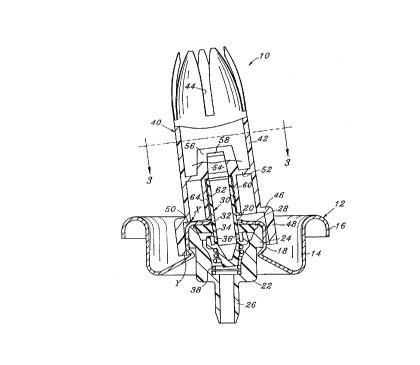
A dispensing assembly is shown in Fig. l and is generally
designated l0. It comprises the valve assembly 12 defined by
the usual mounting cup 14 having a peripheral curl 16 by which
it is mounted on the top of its can (not shown).
As is well known, the cup, which may have a protective
sealing laminate on its underside, is centrally formed with a
pedestal 18 having a central stem opening 20. The lower end of
the pedestal is crimped inward to secure the valve body 22 of
Nylon or other plastic.
The upper end of the body includes an outward flange 24 by
which it is gripped by the pedestal. The lower end includes a
tailpiece 26, and an annular gasket 28 sealingly closes off the
top of the valve body. A valve element 30 is provided with a
(15-S) 5
~172098
tubular stem 32 which extends sealingly through the gasket 28.
The lower end of the stem is formed with an annular upward
sealing lip 34, and the usual pierced discharge port 36 permits
flow when the valve is "open". A spring 38 urges the valve
element upward to sealing position.
The whipped cream actuator 40 may be molded of polypro-
pylene. It includes a general tubular body 42 having at its
open upper end peripherally spaced slots 44 with inwardly
curving petals inbetween to form a "tulip" top. The lower end
is formed with an outward flange 46 and a downward skirt 48.
The underside of the flange 46 (Fig. 2) is formed with a down-
wardly facing annular stop shoulder 50.
The inside of the skirt 48 is tapered, generally comple-
menting the shape of the valve pedestal, spaced therefrom and
extending down far enough to hide it from view for aesthetic
reasons. Intermediate the ends of the actuator 40 is a trans-
verse support partition 52 which is unitary with the actuator
and extends inward to a central passage 54.
Extending upward on either side of the passage 54 is the
inverted U-shaped bridge 56, the sides of which are open and the
(15-S) 6
2172~98
'.. .
top of which is formed with a circular deflector 58 (Fig. 3)
which aligns generally with the passage 54 to assist in the
foaming of the whipped cream and direct it outward through the
open sides of the bridge. Beneath the partition 52 there is
formed a unitary central nipple 60 which, as shown, telescopes
over the tubular stem 30.
As best shown in Fig. 2, retaining means are provided on
the stem and nipple to keep the actuator in ~home~ position
wherein the upper end of the valve stem 32 engages the lower
surface of the partition 52. More specifically, the retaining
means comprises an outward peripheral rib 62 on the stem and an
inward rib 64 on the actuator. Thus in assembly the actuator is
telescoped over the stem and there is a definite "snap" as the
ribs 62, 64 pass each other, indicating retaining engagement and
the arrival of the actuator at the ~home~ position.
With the actuator installed on the container as described,
the operation is similar to the operation of prior whipped cream
dispensers on tilt-type aerosol valves. The container is
inverted and liquid enters the body 22 through the tailpiece 26
and other openings in the bottom (not shown), the compressed
(15-S) 7
2172098
propellent gas being now located above the liquid. When, with
index finger, the user tilts the actuator 40 as shown (Fig. 1)
the sealing ring 34 moves away from the gasket 28 permitting
liquid to pass thereinside, through the port 36, down the
inverted stem 32 into the actuator impacting on deflector 58,
out the sides of the bridge 56 to expand in the chamber above
the bridge and increase the foaming. Whipped cream is dispensed
out the open end of the actuator.
As explained, a limit to the tilting is defined when the
downward shoulder 50 hits the top of the pedestal 18 as shown in
Fig. 1 at X. This absorbs any further force on the actuator
exerted by the user and takes the brunt of the stress otherwise
solely borne by the stem 32. As a result, the assembly is able
to withstand excessive tilting force exerted by the user which
would otherwise fracture the fragile stem 32. In addition, the
lower end of the skirt 48 may contact the lower end of the
pedestal 18 as at Y just above the crimp to help impede further
tilting.
The function of the retaining means 62, 64 is important in
that the upward "creeping" of the actuator on the stem 32 would
(15-S) 8
~17~8
cause the shoulder 50 to rise with respect to the mounting cup
18. This would mean that the stop shoulder 50, during the
operation of the valve, would be too high with the result that
the shoulder would not engage the mounting cup 18 and there
would be no stop action. Thus, the effectiveness of the struc-
ture depends on both the retaining means 62, 64 and the stop
means 18, 50. The secondary contact of the skirt at Y might
also not be made.
Variations in the invention are possible. Thus, while the
invention has been shown in only one embodiment, it is not so
limited but is of a scope defined by the following claim lan-
guage which may be broadened by an extension of the right to
exclude others from making, using or selling the invention as is
appropriate under the doctrine of equivalents.
(15-S) 9