Note: Descriptions are shown in the official language in which they were submitted.
CA 02172349 2006-07-28
-1-
SURGICAL DISSECTOR
BACKGROUND OF THE INVENTION:
This invention relates generally to a surgical instrument for
creating an operative space during surgery. More specifically, it
relates to such an instrument which creates this space by
dissecting a desired layer of tissue from remaining tissue layers.
Tissue dissection to create space at a desired surgical site
has been a focus of design engineers concentrating on the
development of new surgical instrumentation. An increasingly
popular method to dissect tissue involves inflating a balloon
between adjacent tissue layers to separate those layers and create
the desired space. Surgical procedures and instruments
incorporating an inflatable balloon to carry out these procedures
are described in U.S. Patent Nos. 5,309,896 and 5,269,753; and
published PCT International Application Nos. WO 92/212 95 and
WO 93/097 22. Alternatively, dissection can be carried out
manually without the aid of an inflatable balloon.
Another recent development in connection with surgical
instruments is described in U.S. Patent Nos. 5,271,380 and
5,334,150. These patents describe trocars for the penetration of
bodily tissue. Unlike a conventional trocar in which the penetration
of the tissue is performed blindly, the trocars described in these
patents enable the user to simultaneously visualize the penetration
of tissue as the trocar is advanced through the body wall. Trocars
CA 02172349 2006-07-28
-2-
which enable simultaneous visualization are now referred to as "optical
trocars". An optical trocar consists of a rigid tubular shaft to which is
attached a transparent penetrating window. An endoscope for
illuminating the surgical site and transmitting images of the site to the
surgeon is received in the tubular shaft and extends adjacent the
transparent penetrating window.
Unfortunately, the optical trocar described in the patents above
may not always be ideal for creating needed operative space by
carefully dissecting adjacent layers of tissue. In addition, the balloon
dissectors currently available do not provide for simultaneous
visualization as the surgeon is dissecting tissue.
Recently, General Surgical InnovationsTM ("GSI") has shown a
prototype product of what it refers to as the SPACEMAKER TM II
Surgical Balloon Dissector. This dissecting instrument consists of a
rigid hollow shaft to which is attached an inflatable balloon. The
endoscope is insertable through the shaft, and the brochure
accompanying this developmental instrument indicates that the
endoscope is capable of providing for visualization during insertion as
well as during balloon dissection. Unfortunately, when the endoscope
may be inserted through the hollow shaft, the lens on the tip of the
endoscope may be exposed to direct tissue contact as the instrument
is advanced during insertion. The direct contact between the
endoscope lens with the tissue and the lack of separation between
them causes a significant deterioration of the visual capabilities of the
endoscope, and therefore fails to satisfactorily address the problem of
providing adequate visualization during the advancement of a balloon
dissector. In
CA 02172349 2006-07-28
-3-
addition, the position of the endoscope in relation to the inflated
balloon is undesirable for optimum viewing. This is so because the
endoscope is not readily supportable and positionable into and
through a significant portion of the inflated balloon.
In view of these deficiencies inherent in the surgical
instruments described in the references above, the surgical
community needs a balloon dissector which satisfactorily enables
the user to visualize during insertion, and to dissect the tissue
when the balloon is inflated. The surgical community also needs
an instrument which includes an elongate hollow shaft for
receiving an endoscope to provide visualization during surgery, but
also enables the user to position and support the endoscope
significantly beyond the distal end of the shaft for optimum
viewing.
SUMMARY OF THE INVENTION:
In one aspect of the invention, the invention is a surgical
instrument comprising an elongated tubular shaft having a distal
end and a shaft longitudinal axis. A tissue-contacting element is in
communication with the shaft distal end, and at least a portion of
this element is transparent. An inflatable transparent balloon is
attached to the shaft.
The surgical instrument of this invention enables the user to
not only dissect tissue when the balloon is inflated, but also
visualize the tissue as the instrument is advanced when an
CA 02172349 2006-07-28
-4-
endoscope is positioned adjacent to the tissue-contacting element
for viewing. Unlike GSI's SPACEMAKERT"' II Surgical Balloon
Dissector which may allow for direct contact between the
endoscope lens and instrument tissue when the instrument is
advanced, the device of this invention incorporates a tissue-
contacting element preventing direct contact between the tip of
the endoscope and the tissue. Since at least a portion of the
tissue-contacting element is transparent, an endoscope inserted
through the tubular shaft can transmit illuminated images received
from the surgical site through the transparent portion of the
window without requiring direct contact of the endoscope lens
with the tissue.
In another aspect of the invention, the invention is a surgical
instrument for dissecting internal bodily tissue. The instrument
comprises a trocar cannula and an extension assembly. The trocar
cannula has a cannula housing and an elongated tubular sleeve
extending distally from the housing. The trocar cannula is adapted
to slidably receive an endoscope through the housing and tubular
sleeve. The tubular sleeve has a longitudinal axis and a distal end.
The extension assembly is connected to the distal end of
the sleeve and extends distally from the sleeve distal end. The
assembly has a proximal end affixed to the sleeve distal end and a
distal end having a restricting member positioned remote from the
sleeve distal end. A plurality of spaced apart extender arms
connect the assembly proximal end to the assembly distal end.
The extender arms extend in a direction generally parallel to the
CA 02172349 2006-07-28
-5-
longitudinal axis of the sleeve. The extension assembly provides a
passageway through it from the sleeve distal end between the
extender arms to the assembly distal end for receiving and
supporting an endoscope inserted through the assembly for
positioning adjacent the restricting member.
Significantly, the extension assembly connected to the
trocar cannula of the surgical instrument of this invention provides
a supporting structure for an endoscope which is inserted through
the trocar cannula and extends well beyond the distal end of the
tubular sleeve of the cannula. The restricting member at the distal
end of the extension assembly provides a positive stop to prevent
further distal movement of the endoscope beyond the restricting
member, and therefore facilitates the precise positioning of the
endoscope during the tissue dissection procedure. In one preferred
embodiment, an inflatable balloon is affixed to the distal end of the
tubular sleeve of the trocar cannula and surrounds the extender
arms and the restricting member of the extension assembly. This
preferred instrument can then be used as a balloon dissector, and
it has the advantage of enabling the user to supportably extend the
endoscope significantly beyond the distal end of the tubular sleeve
and into and through the lumen of the inflatable balloon. The
comprehensiveness of the visual field and the visual acuity
obtained when the endoscope is positioned in this way during a
tissue dissection is significantly greater than that obtained using
other balloon dissectors which have recently entered the public
domain.
CA 02172349 2006-07-28
-6-
The surgical instruments of this invention can be used in
any procedure where it is desirable to inflate a balloon to provide
for the dissection of bodily tissue. Alternatively, they can be used
to perform a manual dissection without the aid of a balloon where
it is desirable to provide enhanced simultaneous visualization. The
instruments can be used in conventional as well as endoscopic
surgical procedures, although the instrument is particularly adapted
for endoscopic surgical procedures such as laparoscopic hernia
repair, laparoscopic bladder neck suspension, and lymph node
dissections.
Brief Description of the Drawings
Figure 1 is a perspective of an assembly including the
surgical instrument of this invention configured as a balloon
dissector shown in a deflated position.
Figure 2 is a perspective view of the assembly where the
balloon dissector is shown in an inflated position.
Figures 3-5 are side elevational views, partially broken
away, showing how the assembly is used to dissect internal layers
of tissue to create an operative space on a surgical patient.
Figure 6 is an exploded perspective view of the assembly.
CA 02172349 2006-07-28
-7-
Figure 7 is a partial side elevational view of the assembly
with portions broken away to disclose the method of inflating the
balloon dissector.
Figure 8 is a cross-sectional view of the extender arms of
the extension assembly which forms a part of the preferred bailoon
dissector as taken along section line 8-8 of Figure 7.
Figure 9 is an enlarged side view illustrating the abutting
relationship between the distal end of the endoscope and the
restricting member at the distal end of the extension assembly as
seen along view line 9-9 of Figure 8.
Detailed Description of the Preferred Embodiment
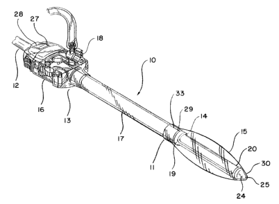
The preferred surgical instrument of this invention includes
an assembly 10 having a balloon dissector 11 as the primary
component. The assembly is best illustrated in Figures 1, 2, and
7. The assembly consists of two primary components. These
components are the balloon dissector 11 for the dissection of
internal bodily tissue to create an operative space during a surgical
procedure, and an endoscope 12 in cooperation with the balloon
dissector to provide simultaneous visualization during the surgical
procedure as the dissector is advanced through tissue and the
operative space is created.
The balloon dissector consists of a conventional trocar
cannula 13, an extension assembly 14 to position and provide
CA 02172349 2006-07-28
-8-
support for an endoscope, and an inflatable balloon 15. The trocar
cannula has a cannula housing 16 providing a passageway to an
elongated tubular sleeve 17 extending distally from the housing.
The housing contains a conventional stop-cock valve 18 to
selectively provide for the flow of a pressurized fluid such as air
from a suitable external source through the housing and sleeve into
the balloon. The tubular sleeve 17 of the cannula is sized to
slidably receive an endoscope. The sleeve has a distal end 33, and
the sleeve defines a longitudinal axis designated as "L" in Figure 6.
The extension assembly 14 is attached to the distal end of
the tubular sleeve of the cannula. The extension assembly has
proximal and distal ends, 19 and 20, respectively, and provides a
passageway 34 from the proximal end to the distal end to receive,
position and support the endoscope 12 protruding from the distal
end of the tubular sleeve. The assembly proximal end is shaped
as a short tube 21 which can be removably or permanently
secured within the internal diameter of the tubular sleeve as
illustrated in Figure 7. Alternatively, it can be secured externally to
the outer diameter of the sleeve.
Three extender arms 22 extend from the short tube 21 at
the proximal end of the extension assembly and terminate at the
distal end of the extension assembly. Although three arms are
shown, it may be desirable to construct the extension assembly
with four arms to provide enhanced support without appreciably
sacrificing optical quality during visual observation using the
endoscope. The extender arms 22 are displayed generally parallel
CA 02172349 2006-07-28
-9-
to the longitudinal axis L of the tubular sleeve of the cannula, and
therefore do not obstruct the passageway when the endoscope is
inserted into and through the extension assembly.
The extension assembly is desirably composed of a resilient
plastic so that the extender arms provide resiliency without
sacrificing needed support. This resiliency in turn provides needed
flexibility as the instrument is advanced during surgery. The
extender arms are connected at the distal end of the extension
assembly with a restricting member in the form of a ring 23. The
ring has an internal diameter smaller than the internal diameter of
the tubular sleeve of the cannula and of the endoscope 12. The
ring therefore blocks distal movement of the endoscope at the
distal end of the extension assembly to facilitate the desired
positioning of the endoscope (see Figure 9).
In one preferred embodiment, a tissue-contacting element
24 is fastened to the distal end 20 of the extension assembly
adjacent the ring 23. The tissue-contacting element is a
transparent, hollow cone which acts as a window for the
endoscope and helps to prevent direct contact between the
endoscope and internal bodily tissue as the instrument is advanced
during a surgical procedure. The cone has a blunt tip 25 to ensure
atraumatic blunt tissue dissection and is positioned on the
extension assembly so that it is symmetrical about the longitudinal
axis of the tubular sleeve.
CA 02172349 2006-07-28
-10-
The endoscope is a conventional, fully-integrated rigid
endoscope which provides the delivery of light into the body from
an external source and transmits images from the illuminated body
cavity to the surgeon at an eye piece or a video monitor,
whichever is desirable. The endoscope is releaseably inserted into
the trocar cannula and through the tubular sleeve of the cannula.
It protrudes beyond the sleeve distal end into the passageway and
structural support provided by the extension assembly. In this
particular embodiment, the endoscope can be inserted distally until
it abuts not only the ring 23 at the distal end of the extension
assembly, but also an internal annulus 26 of the tissue-contacting
element adjacent the ring. When a light source is activated, the
light is delivered through the endoscope and exits the distal end of
the endoscope. The light travels through the transparent conical
window of the tissue-contacting element and is emitted into the
body cavity to provide illumination. The illuminated images from
the body cavity are reflected back through the window and are
transmitted through the endoscope to provide the surgeon with
the illuminated images in the conventional manner. The endoscope
is securely supported and positioned within the extension
assembly, and the tissue-contacting element provides a barrier
between the tissue as it is being dissected and the distal end of
the endoscope.
To provide further support and precise positioning of the
endoscope within the extension assembly, the trocar cannula 16
includes a locking assembly 27 affixed to the cannula housing.
The locking assembly has a latch 28 to secure the endoscope in a
CA 02172349 2006-07-28
-11-
desired position during use. This locking assembly is described in
more detaii in co-pending application U.S. Patent No. 5,569,292.
The last component of the assembly incorporating the balloon dissector
is, of course, the inflatable balloon 15. The balloon is preferably made
of a puncture-resistant, distensible material compatible with human
tissue. Preferably, the balloon is composed of a silicone elastomer.
The balloon has a proximal end 29 affixed to the distal end of the
tubular sleeve of the cannula. Alternatively, if the extension assembly
14 is affixed to the outer diameter of the tubular sleeve, then the
proximal end of the balloon can be attached to the extension assembly
proximal end. The proximal end of the balloon can be attached using
conventional methods such as heat sealing. The extension assembly
and the tissue-contacting element protrude into the lumen of the
balloon, and therefore the balloon completely surrounds and envelopes
these components. The distal end of the balloon 30 fits snugly over the
tissue-contacting element when the balloon is in a deflated position.
As illustrated in Figure 7, the balloon is inflated when the stop-cock
valve mounted on the trocar cannula is turned on to permit the passage
of pressurized air in the direction of the arrows through the tubular
sleeve and into the lumen of the balloon to inflate the balloon. Once
the balloon is inflated, the stop-cock valve is turned off, and the balloon
will maintain its inflated condition until it is desired to deflate the
balloon. At this point, the
CA 02172349 2006-07-28
-12-
source of pressurized air is removed, and the stop-cock valve is
once again turned on to allow the air inside the inflated balloon to
escape through the tubular sleeve and out of the stop-cock valve
of the trocar cannula. Although the inflated balloon is illustrated as
a spherical balloon, other desired shapes can be used, and the
shape of the balloon is not an essential feature of this invention.
In an alternative embodiment (not shown), the assembly
does not include the tissue-contacting element, and the endoscope
simply abuts only the ring at the distal end of the extension
assembly for desired support and positioning of the endoscope.
The use of the assembly including the balloon dissector
during a surgical procedure to dissect internal bodily tissue for the
creation of an operative space is illustrated in Figures 3-6. An
exposed portion of a surgical patient 31 is illustrated. The exposed
portion of the patient includes internal layers of bodily tissue 32.
To dissect away certain layers of the tissue from other layers, the
assembly is inserted through the outer layers of the skin and
advanced in a direction generally parallel to the adjacent layers of
the internal bodily tissue. Concurrently with the advancement of
the assembly through the tissue, the surgeon will visualize the
advancement using the endoscope. Once the surgeon has
advanced the assembly to the desired position within the bodily
tissue, the balloon is inflated through the cannula sleeve to further
separate the adjacent layers of tissue. Significantly, the protrusion
of the endoscope well beyond the sleeve distal end into and
through the extension assembly greatly enhances the visual field
CA 02172349 2006-07-28
-13-
for the surgeon as the dissection progresses. The visual clarity
and comprehensiveness of the visual field is appreciably greater
than what it would be if the endoscope did not extend beyond the
sleeve distal end, or if the extension assembly were replaced with
a tubular extension.
After the balloon is sufficiently inflated to separate the
tissue, the balloon is then deflated. The assembly including the
balloon dissector may then be removed from the patient, and
another trocar cannula 35 can be introduced into the patient where
the space has been created (see specifically Figure 5). The
surgeon can then perform therapeutic or diagnostic procedures
within the operative space created using the new trocar cannula as
a passageway for other surgical instruments.
This invention has been described in connection with a
specific preferred embodiment. The descriptions provided to
illustrate this embodiment should not be used as a basis for a
narrow or limited construction of the language set forth in the
appended claims. Quite the contrary, the appended claims should
be interpreted broadly because one skilled in this art can readily
envision numerous additional embodiments which have not been
specifically described but nevertheless would fall within the scope
and spirit of the claimed invention.