Note: Descriptions are shown in the official language in which they were submitted.
WO95/06891 ~. 2 1 7 2 5 3 2 PCT/GB94/01906
Description
OPTICAL FIBRE TERMINATION
The present invention relates to improvements in connections to
optical fibres.
Telecommunication systems using optical fibres often employ
cables containing large numbers of optical fibres. As the signal path
approaches the individual subscriber or a central office or other
interface it is necessary to provide connections to individual optical
fibres or to groups of fibres. This generally involves separating the
fibres and arranging the fibres into an appropriate configuration for
connection to another fibre. This arrangement and general handling of
the fibres must be carefully m~n~ed to avoid excessive kinking or
strain on the fibres or any other fl~m~e to the fibres. Nonetheless
during their installation and service optical fibres may be exposed to
considerable axial forces. For example one method by which a person
installing a number of optical fibres can trace the path of any individual
fibre, to locate that fibre further on in the bundle, is to pull on the end
part of the fibre, and note which fibre moves.
Various protection is provided around the optical fibres.
For example the optical fibres may be surrounded by one, or several
coatings which gives some protection both against physical damage and
loss of light, and gives the fibre a certain amount of stiffness. Also
optical ~lbres often run in so-called transportation tubes, which provide
additional protection, and still further protection may be provided by
additional reinforcing m~teri~l, in fibrous form, provided between the
outer tube and the internal optical fibre. This reinforcement may
comprise thin, flexible, high strength fibres e.g. fibres sold under the
trade name "Kevlar", which extend longitudinally inside the outer
transport tube.
Where connections are to be made to the optical fibres it is usual
to cut baclk the outer protection transport tube, and fold away the
reinforcing fibres, so that the inner coated fibres then extend on to the
WO95/06891 ~ 2 1 7 2 5 3 2 PCT/GB94/01906
- 2 -
connection apparatus. (Additional short lengths of transport tubes may
also be provided around the coated fibres extending from the cut back
protection tubes and reinforcing-fibres.)
When making connections involving optical fibres it is very
important to avoid kinking of the optical fibres, since kinking may
result in impaired light tr~n~mission, and possibly permanently damage
to the fibres. As a result, it is desirable to termin~te the cut back
protection tube and reinforcing-fibres surrounding the central optical
fibre so that any axial pull on the fibre tube is transmitted to the
bulkhead or other structure at which the tube is termin~ted or spliced
and not to the fibre contained within the tube. Techniques for splicing
or te.rmin~ting coaxial or other metal cables would not therefore be
expected automatically to be suitable for splicing or termin~ting optical
fibre cables.
Optical fibres running in transportation tubes are sometimes
provided in the form of pigtails, that is generally short lengths of fibre,
typically pre-factory-mounted with a connector at one or both ends.
The short length pigtails are advantageously used when connecting
different parts of a network, rather than connecting the fibres of the
different parts of the network directly to each other. The use of pigtails
minimises the h~n(lling of the main lengths of the optical fibres.
It is an object of the present invention to provide an effective
means of termin~tin,~ optical fibres which holds tubes and reinforcing-
fibres containing the optical fibres against high axial forces, but which
leaves the internal optical fibres unstressed and free to pass on for
splicing or termin~tion themselves. In particular, the invention
provides for splicing or te-rmin~ting at least two (sometimes two, three,
four, or even up to about twelve) optical fibre tubes side-by-side. For
example send and return fibres, or a main and a back-up fibre could be
spliced or termin~ted in pairs.
The present invention provides a device for termin~ting or
splicing at least two tubes carrying optical fibres surrounded by
reinforcing fibres, which device comprises first and second parts which
WO 95/06891 . : ` - 2 1 7 2 5 3 2 PCT/GB94/01906
- 3 -
can be secured together during termination or splicing, such that a
portion of an optical fibre within each tube extends through aligned
apertures in the parts, and such that the reinforcing fibres are gripped
between the secured parts.
The first and second parts can preferably be mechanically
attached to a bl11khe~d etc. where the tubes are to be termin~ted, or, for
example, to another pair of such parts in the case of a splice.
The first and second parts may be provided with mating screw
threads, or snap fit parts or the like, to effect the securement together.
Where the first and second parts comprise mating screw threads,
the parts are preferably made of metal, or polymeric m~teri~l. Where
the parts comprise snap fit mating parts, the parts preferably
comprising an electrically ins~ ting m~teri~l, and are preferably made
from polymeric material.
Preferably the m~ting parts are such that re-entry is possible, i.e.
it is possible to reopen the screw or snap connection once it has been
made. The device advantageously is such that it can be installed and re-
entered on site, by the installer, without tools
The present invention also provides a method of termin~ting or
splicing at least two tubes carrying optical fibres, each having
reinforcing fibres surrounding the optical fibre within the device of the
invention, which method comprises:
a) removing a portion of the end of each tube so as to expose the
optical fibre portion and the reinforcing fibres,
b) inserting the optical fibre portion, and the exposed reinforcing
fibres of each tube through an aperture in the first of said device
parts,
c) securing the second of said device parts relative to the first of said
parts, such that the optical fibre portions e~tend through the
WO 95/06891 ~ 2 1 7 2 5 3 2 PCT/GB94/01906
apertures in the parts and the reinforcing fibres of the optical
fibres are gripped between the first and second device parts.
The first and second parts are secured relative to each other so
that the reinforcin~-fibres surrounding the optical fibre are gripped
between the parts. To this end the second part is ~refel~bly posi~ioned
to surround at least part of the first part. As another option the second
part may be positioned within the second part. The first and second
parts are preferably hollow. They are preferably also generally
cylindrical.
Where the second part surrounds at least part of the first part, the
method preferably also comprises folding back the reinforcing fibres
over the outer surface of said first part prior to positioning the second
part thereover.
One of the said first and second parts, or both is preferably
adapted so it can be mechanically attached to a bulkhead etc. where the
tubes are to be termin~t~d, or to another pair of such parts in the case of
a splice.
For some applications, where said second part is secured over
said first part, it may be desirable to use a cylindrical part such as a
collet in addition to the first and second m~ting parts. The collet may
be placed to extend within the first part over the op~cal fibre portions
and wi~in the reinforcing fibres after the reinforcing fibres have been
folded back over the outside of said first part. The second part is then
placed over the first part and secured relative thereto. The collet can
locate and internally support the reinforcing fibres, provide additional
protection for the optical fibre portions. Preferably the collet has an
outwardly directed flange at one end which projects over the thickness
of ~e wall of the first part. In this case the collet can also help to
position the first part relative to the optical fibres, since its outwardly
directed flanges can abut and locate the ends of the tubes surrounding
the optical fibres. Where the collet has outwardly directed flanges at
one end, these are preferably suf~lciently small that the said second part
W095/06891L ` . 2 1 7 2 5 3 ~ PCT/GB9~/01906
~ 5 _
can fit over the collet flanges to engage and be secured to the said first
part.
When the first and second parts comprise screw threads to secure
them together, they are preferably provided with nut portions so
enabling the two parts to be screwed together by means of a spanner.
Preferably the m~ting screw threaded surfaces are so disposed that the
reinforcing fibres are gripped between them.
Preferably only two jacketed optical fibres are connected
together. I have surprisingly found that sufficient transfer of axial
loads from the reinforcing-fibres surrounding the optical fibres to the
first and second parts of the device of the invention (and then to a
bulkhead etc) can be achieved without the parts being secured together
so tightly that ~l~m~e occurs. Instead of screw threads or a snap fit
other mating surfaces that may be mentioned include interengaging
tapering surfaces or bayonet fixings. Such surfaces may be driven by
screw threads if desired.
In some embodiments according to the invention, where two or
more optical fibres are to be termin~ted side by side the first and second
parts contain a single aperture through which both optical fibres (and
their respective surrounding tubes and reinforcing fibres pass). In a
preferred embodiment according to the invention, one of the first and
second parts comprises a projechng porhon comprising open channels
into which the coated optical fibres, projecting from the cut back
transportation tubing, can be positioned. The open channel
configuration makes it easy ~or the installer tO view and organise the
optical fibres, while the reinforcing-fibres are folded back over the cut
back tube and the said ~lrst part (or the rem~ining part of the said first
part where the projechng porhon projects from the said first part.
Embodiments of the invention will now be described with
erelellce to the accompanying drawings in which:
~ .
Figure 1 is an exploded side view of a device according to the
invenhon;
.
WO95/06891 . 2 ~ 72~32 PCT/GBg4/01906
Figure 2 is a cross-sectional side view of the device of Figure 1 in
unexploded form;
Figure 3 is a side view of the device of Figures 1 and 2 in use.
Figures 4 and 5 are perspective views of the first and second parts
respectively of a second device according to the invention;
Figures 6 and 7 are sectional views through Figures 4 and 5
respectively;
Figure 8 is a sectional view showing the parts of Figures 4 to 7
installed in a bulkhead;
Figure 9 is a schematic view showing the passage of optical fibre
tubes through the configuration of Figure 8;
Figure 10 is a perspective view of a first part of a third device;
Figures 11 and 12 are perspective views of a first and second part
respectively of ano~er embodiment according to ~e invention;
Figures 13 and 14 are perspective views (Figure 14 being a partly
transparent view) of assembled first and second parts of another
embo~lim~nt according to the invenhon.
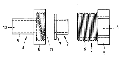
Referring now to the drawings, Figure 1 shows a device which
comprises a first part 1 for receiving a tube, and fibre reinforced
optical fibre, a cylindrical part (collet) 2, and a second part 3.
The first part 1 has an internal bore or aperture 4 into which two
tubes can be inserted, a head 5 and an externally threaded portion 6.
The collet 2 has a diameter such that it can fit within the bore 4 of
part 4 but also an outwardly directed flange 7 arranged to project across
the wall thickness of part 1 and therefore limit the penetration of the
wo gs/068gl ~ 1 7 ~ ~ 3 2 PCT/GB94/01906
~ - 7 -
collet into part 1. The second part 3 of the device comprises a nut
portion 8 and an elongate portion 9 having a bore 10 therethrough. Nut
portion ~ has an internally threaded recess 11 which mates with the
external screw threaded part S of first part 1.
In use the ends of each transportation tube 12, 13 surrounding the
fibre reinforced optical fibres are removed to expose the optical fibres
14, 15 (which may be coated or otherwise protected) and the
reinforcing fibres 16, 17. The optical fibres 14, 15 and reinforcing
fibres 16, 17 are passed through the bore 4 in the first part 1. The
reinforcing fibres 16, 17 are then folded back over the externally
threaded portion S of the first part 1 of the device. The collet 2 is
passed into the first part 1 of the device over the optical fibres 14, 15
within the reinforcing fibres 16, 17. It thereby locates the first part 1
relative to the cut back tubes 12, 13, since the ends of the cut back tubes
12, 13 abut against the outwardly directed flange 7 on the collet 2. The
second part 3 of the device is then placed over the optical fibres 14, 15
so that they pass through the bore 10. The second part 3 is then
screwed down on to the first part 1 of the device, gripping and trapping
the reinforcing fibres 16, 17 between the screw thread portions of the
first and second parts 1, 3 of the device.
Turning now to the second device according to the invention
shown in Figures 4 - 9, the first part 21 of the device is shown in Figure
4. It is generally cylindrical in shape but comprises adjacent to each
other, an annular ridge 22, groove 24 and collar 26 on its outer surface.
These serve together to form an arrangement that can co-operate with a
bulkhead (described in detail later). The part 21 also comprises a tube
portion 28 extending ~rom the collar 26, and having on its outer
surface, part way along its length, a low profile ridge 30. This provides
part of the snap fit mechanism of the device as described later. A
cylindrical aperture 32 extends through the entire part 21, for passage
in use of optical fibre tubes.
Figure S shows the second part 33 of the device of the first
embodiment. It comprises a cylindrical part 34, having on its internal
surface a low profile annular groove 38. Groove 38 is a snap fit with
WO95106891 - . . . 2 1 72532 PCTtGB94/01906
- 8 -
ridge 40 of the first part. The second part 33 also has an aperture 36
extending through its lerlgth for passage of the optical fibres and is
provided with an end wall 40.
Each of the parts 21 and 33 is integrally formed. They are each
made from polymeric material, for example a high strength polymer.
Polymers that can be used include fluoropolymers, for example
"Kevlar"- trade mark). The parts 21 and 33 are preferably moulded.
The constituent features of parts 21 and 33 can also be seen in the
sectional views (Figures 6 and 7). As shown in these Figures some
dimensions of the part are as follows:
Figure 6 - Part 21
Diameter "d,", (of aperture 32 in first part 21) 4.5rnm
Total length "1" (of first part 21) 20.0rnm
Diameter "d2" (inner diameter of collar 26 on part 21) 5.2rnm
Height "hl" (of ridge 30) 0.28 mm
Fi~ure 7 - Part 33
diameter d3(inner diameter of groove 18) 8.33rnrn
diameter d4(inner diameter for entry of part 21) 10.2rnm
diameter d5 (exit diameter for optical fibres and
reinforcing braids) 4.5rnrn
height hl (height of groove 18) 0.76mm
thickness tl (of end wall 40) 1.0 rnm
The Figures as drawn are approximately four times actual size
(unless stated otherwise).
Figure 8 shows the part 21 installed in a bulkhead 42. Part 33 is
not shown for clarity. The ridge 22 on the part 21 must be sufficiently
small to pass through the opening in the bulkhead, and then an
additional part 44 is required to engage with the ridge 22 on the
inserted side of the bulkhead to retain part 21 in the blllkhe~ 42. The
ridge 42 engages in a snap fit with the additional piece 44, which in turn
abuts against the bulkhead 42. Thus the device of this aspect of the
j~ ~
wo 95/06891 - 2 1 7 2 5 3 2 PCT/GBg4/0l906
g
invention has two snap fit parts. A first snap fit of the two parts of the
device together, and a second snap fit to the bulkhead or the like. This
makes for particularly easy installation.
Figure 9 shows the position of the device 21 and 33 adjacent a
bulkhead 42 with pigtails of optical fibres 44 passing therethrough. A
weight 24 (10 kg) is shown to illustrate testing of the installation.
Fibres installed in this way can resist a weight of 10 kg without kinkinp.,
or other damage to the fibres.
Figures 10 is a perspective view of a first part of another
embodiment of the invention. Like parts are referred to with like
reference numerals to the embodiment shown in Figures 4, 6 and 8.
This part will co-operate with the same second part 33 shown in Figures
5 and 7, ridge 30' of part 21' snap-fitting with groove 38 of part 33.
The major difference between these two embodiments is the shape of
ridge 22l. In the embodiment in Figures 10 and 12, part 22' is shorter
in one transverse dimension than another. This could be inserted in a
buLlchead or the like in any suitable manner. It could for example be
inserted through an aperture in the blllkhe~-l that is intermediate in size
between the longer and shorter dimensions of part 22', and then simply
rotated to retain it in place, with some appropriate locking means to
prevent re-rotation.
Figure 11 shows the first part of a third embodiment of the
invention, and Figure 12 shows co-operating second part of that
embodiment. In ~is case, in place of the ridge 30 on the outer surface
the first part engaging a groove 38 in the second part (as shown in
earlier Figures), four projecting portions 50, e~ually spaced around the
outer surface first part 21", co-operate with simil~r spaced apertures
52 in a generally cylindrical second part 33". Again the co-operation is
a snap fit. As before the end of the first part 21" distant from the
projecting portions SO may be configured for easy connection to a
bulkhead, plate or the like. Again the parts are from the same
m~teri~ls, and preferably made in the same way as the embodiments of
the earlier Figures.
WO95106891 ` ~ 2 1 72532 PCT/GB9~/01906 ~
- 10 -
Referring now to Figures 13 and 14, a first part 21"' fits within,
and is a snap fit, with second part 33"'. The snap fit is provided by
four equally spaced apertures on part 21"' co-operating with four
equally spaced projections on the inner surface of surrounding part
33"' (see Figure 14). As before a common aperture (in this case
referenced as ~8) extends through both parts 21"' and 33"'. Two
pigtails (with cut back outer tubing) which are to be termin~ted are
passed through aperture 58, and then the reinforcing braids
surrounding the fibres themselves are folded back over the outer
surface of part 21"', and within part 33"', so that they are trapped
between the parts. The pigtails are not shown in the figures for clarity.
The pigtails are, of course, inserted, and the reinforcing fibres
positioned between parts 21"' and 33"', prior to positioning and snap
fitting part 33"' over part 21"'. In this embodiment an extra feature is
provided on the inner part 21"' in the form of an extending projection
62, extending beyond the end 64 of the common aperture 58 through
parts 21"' and 33"'. This projection comprises two open channels 66
for receiving respective ones of the fibres from the pair of pigtails,
which at this point have been separated from the surrounding
reinforcing fibres. The fibres may be coated (with a primary and
optionally a secondary coating) in the ch~nnel~ 66, but they are not
surrounded by reinforci~g fibres. The channels 66 may even be sized
to accommodate the fibres in transportation tubes if desired. The
channels 66 provide additional support for the fibres. The open
configuration of the ch~nnels also makes it easy for the installer to sort
and organise the fibres relative to each other.
In use of the devices of the invention the ends of each tube
cont~ining optical fi~res are removed to expose the optical fibre (which
may be coated or otherwise protected) and the reinforcing fibres. The
optical fibres and reinforcing fibres are passed through the apertures
in the first of the two parts of the devices (generally indicated as 1 or
21) The reinforcing fibres are then folded back over the first part 1 or
21 and then the second part 13 or 33) is passed over the optical fibres
and fitted (e.g. screwed, snap fitted or otherwise) to the first part
thereby trapping the reinforcing fi~res between the parts 1 or 21 and 13
or 33 of the devices of the inven~ion.
~WO 95/06891 2 1 7 2 5 3 2 PCT/GB94/01906
Connections made as described above have been found to ha~e a
good resistance to axial forces resulting from pulling on the jacket (e.g.
testing with a 10 kg weight) but do not result in kinking of the optical
fibres. It is surprising that two such tubes can be termin~ted or spliced
in this way since axial pull on the tubes is likely to be laterally off-set
from either fibre axis and would be expected to result in unacceptable
microber3ding or other deformation of the fibres.
In general, the method of the invention will be used to termin~t~
pairs of tubes at a bulkhead or frame or other part of a cable splice or
splitter housing. The bulkhead, frame or other part may include a plate
having a hole or slot through which the fibres pass and at which the
tubes are termin~ted. The fibres past the plate will then not be stressed
by axial pull on the tubes, since that stress will be taken up by the plate.