Note: Descriptions are shown in the official language in which they were submitted.
7745
BACKGROUND OF THE INVENTION
2
3
4 1. Field of the invention:
This invention relates in general to variable
6 capacity vane compressors for air conditioning systems,
7 particularly for vehicles.
8
9 2. Description of the Prior Art:
One type of automotive air conditioning compressor
11 in use is a variable capacity vane compressor. In this
12 type of compressor, a compression housing has a chamber
13 that is oval in shape. A cylindrical rotor rotates
14 within the chamber. The rotor has radial vanes mounted
to it which slide in slots formed in the rotor.
16 Refrigerant at suction pressure enters the compression
17 chamber. The vanes compress the refrigerant, which
18 passes outward through a valve.
19 The compressor demand varies according to speed and
atmospheric conditions. At highway speed, the demand is
21 usually. lower than while idling on a hot day. To vary
22 the capacity, a rotary valve disk or plate mounts in
23 engagement with a shoulder on the compression housing.
24 The valve plate has lobes on its perimeter which will
change the position of the opening from the suction
26 chamber into the compression chamber, depending upon the
27 rotational position of the valve plate.
28 U.S. Patent 5,364,235 shows a linearly moving
29 actuator which will rotate the valve plate to selected
positions depending upon changes in the discharge and
31 intake pressures. A control valve supplies a control
32 pressure to one side of the actuator, and the other side
33 of the actuator is at intake pressure. The control valve
34 operates in response to varying intake and discharge
pressures.
2
~ 1z~~5
1 The linear actuator has a spring which urges the
2 actuator away from the intake side toward the control
3 pressure side. The spring will position the actuator in
4 the minimum delivery position when the compressor is not
operating. Tests have shown that pressure surges
6 sometimes occur, causing the actuator to move rapidly
7 from the minimum delivery to the maximum delivery
8 position. This rapid shift in position has
9 disadvantages.
U.S. Patent 5,364,235 also discloses a pressure
11 chamber for applying an axial force on a rotary valve
12 plate that is proportional to the control pressure. The
13 annular pressure chamber is located in a recess that
14 contains a seal. The seal applies a force to a bearing
pack which in turns engages the valve plate. In the '235
16 patent, the bearing pack components are located partially
17 within a recess in the valve plate, and partially within
18 a portion of the valve housing. While workable for
19 applying the desired pressure to the valve plate, this
arrangement results in assembly difficulties.
21 .
3
..... ~ ~ 727
1 SUI~iARY OF THE INVENTION
2 In this invention, the linear actuator utili2es two
3 springs. The second spring is located on the control
4 pressure side of the actuator. It urges the actuator
member toward the suction side, while the suction
6 pressure side spring urges the actuator toward the
7 control side. The two springs are arranged so that
8 equilibrium is reached with the actuator in an
9 intermediate position between the full delivery and
minimum delivery positions while the compressor is off.
11 Preferably, the control pressure side spring has its
12 outer end positioned so that it will contact a stop and
13 apply a force only when during or near the minimum
14 delivery position. The control side spring does not have
any effect once the actuator is past the selected
16 intermediate position and closer to the maximum delivery
17 position.
18 The thrust bearing pack for applying axial thrust to
19 the valve plate is located entirely within the same
recess which contains the seal for delivering the control
21 pressure. The face of the thrust bearing is flush with
22 the support face of the valve housing. The valve plate
23 has a smooth, flat face extending from a central
24 counterbore to the outer diameter of the thrust bearing.
4
~ rz~~~
1 DESCRIPTION OF THE DRAWINGS
2
3 Figure 1 is a partial sectional view illustrating
a
4 compressor constructed
in accordance
with this invention.
6 Figure 2 is another sectional view of the compressor
7 of Figure 1, taken along the section line 2-2 of Figure
8 1.
9
Figure 3 is a partial sectional view of the
11 compressor of
Figure 1, taken
along the section
line 3-3
12 of Figure 2.
13
14 Figure 4 is another partial sectional view of the
compressor o f Figure 1, taken along the section line 4-4
16 of Figure 3, and with a portion of the rear head shown
in
17 section.
18
19 Figure 5 is a sectional view similar to Figure 2,
but enlarged and shown with the actuator moved to another
21 position.
22
23 Figure 6 is a sectional view of the compressor of
24 Figure 1, ta ken along the line of 6-6 of Figure 1.
26 Figure 7 is a rear elevational view of the rotary
27 valve plate used with the compressor of Figure 1.
5
~l ~~1~5
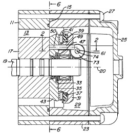
1 DETAILED DESCRIPTION OF THE INVENTION
2 Referring to Figure 1, the compressor has a
3 compression housing 11. Compression housing 11 has a
4 compression chamber 13 which is oval in shape, as shown
in Figure 6. A shoulder 15 faces in a rearward
6 direction, with "rearward" being an arbitrary reference.
7 Rotor 17 has a cylindrical configuration, as shown in
8 Figure 6, and is rotated within compression chamber 13 on
9 a rotational axis 20. Shaft 19 drives rotor 17 and is
connected to a drive source (not shown).
11 Referring still to Figure 6, a plurality of vanes 21
12 extend outward from slots within rotor 17. Vanes 21
13 engage the sidewall of compression chamber 13 to compress
14 refrigerant as rotor 17 rotates. A discharge valve 22
allows the discharge of refrigerant from compression
16 chamber 13 into a discharge chamber (not shown) located
17 on the opposite end.
18 Referring again to Figure 1, valve housing 23, also
19 called a rear side block, abuts compression chamber
shoulder 15. A rear head 25 is secured to the opposite
21 side of'valve housing 23. Bolts 27 secure rear head 25
22 and valve housing 23 to compression housing 11. An
23 intake or suction chamber 29 is located within rear head
24 25 and valve housing 23.
Valve housing 23 has a central portion 31 which is
26 surrounded by passages leading from intake chamber 29 to
27 compression chamber 13. Central portion 31 is located on
28 the longitudinal axis 20 of shaft 19. A circular boss
29 33 surrounds a hole extending through central portion 31,
which receives shaft 19. A face 35 extends radially from
31 boss 33.
32 A recess 37 is formed at the outer perimeter of face
33 35. Recess 37 is located close to the periphery of
34 central portion 31. Recess 37 is annular and rectangular
in transverse cross-section. A seal 39, either a spring
6
217~7~5
1 actuated lip type, or elastomeric type, is located in
2 recess 37. A bearing pack 41 is located in engagement
3 with seal 39. Bearing pack 41 is a roller type bearing
4 having a front thrust washer, a rear thrust washer and
caged rollers located between. The rear thrust washer is
6 in contact with seal 39. The front thrust washer bears
7 against the rear face of valve plate 43. The inner
8 diameter of the assembled bearing pack 41 is closely
9 received on a cylindrical inner wall of recess 37.
A valve plate 43 is sandwiched between compression
11 chamber shoulder 15 and face 35. Valve plate 43 is
12 fitted with a central seal which rotatably receives shaft
13 19. Valve plate 43 is a generally flat disk having a
14 pair of peripheral lobes 45, shown in Figure 7.
Referring again to Figure 1, a counterbore 47 is formed
16 in valve plate 43 for closely receiving boss 33. The
17 rearward face of valve plate 43 from counterbore 47 to
18 the periphery is a flat surface perpendicular to the
19 longitudinal axis of shaft 19. A cylindrical steel pin
49 is rigidly secured to valve plate 43 and extends in a
21 rearward direction on a pin axis 50 which is parallel to
22 and offset from the longitudinal axis of shaft 19. Pin
23 49 is used to rotate valve plate 43 between minimum
24 delivery and maximum delivery positions.
Referring to Figure 2, an intake pressure bare 51
26 and a control pressure bore 53 are formed in valve
27 housing 23 perpendicular to longitudinal axis 20. Bores
28 51, 53 are co-axial and of the same diameter in the
29 preferred embodiment. Bores 51, 53 are separated by a
portion of intake chamber 29. Intake pressure bore 51 is
31 closed on its outer end by an end cap 55. An end cap 57
32 closes the outer end of control pressure bore 53. Pins
33 59 are used to secure end caps 55, 57 to valve housing
34 23.
7
27 7~1~5
1 An actuator member 61 is reciprocally carried in
2 bores 51, 53. Actuator member 61 is a linearly moving
3 piston. An intake side spring 63 locates within a recess
4 formed in actuator 61. Intake side spring 63 has one end
that continually engages end cap 55. Intake side spring
6 63 is continually under some compression, urging actuator
7 61 to the left, which is the minimum delivery position of
8 valve plate 43. An intake side stop 65 provides a limit
9 to the travel of actuator 61 to the right, determining
the maximum delivery position of valve plate 43. The
11 portion of actuator 61 that is received within intake
12 side bore 51 does not form a seal or piston, rather
13 clearances exist which communicate with intake chamber
14 29. Furthermore, an additional passage (not shown)
communicates intake chamber 29 to intake pressure bore 51
16 and thus to the recess which contains intake spring 63.
17 The left or control side end of actuator 61 contains
18 a seal 67 which sealingly engages control pressure bore
19 53. Control pressure bore 53 communicates with control
pressure as subsequently described, which applies
21 pressure between seal 67 and end cap 57. A control side
22 spring 69 and a cylindrical spacer 68, which may be
23 considered a part of spring 69, are located within a
24 recess 70 formed in actuator 61. Control side spring 69
and spacer 68 are fully contained within the recess 70,
26 with the outer end of spacer 68 terminating a selected
27 distance from the left-hand end of actuator 61. A stop
28 71 is rigidly secured to end cap 57 and protrudes toward
29 end cap 55 for contact with spacer 68 within recess 70.
Stop 71, spacer 68 and spring 69 have lengths
31 selected such that spacer 68 will contact stop 71 only
32 when actuator 61 has moved to a selected intermediate or
33 equilibrium point between the minimum delivery position
34 on the left and the maximum delivery position on the
right. When the compressor is not operating, intake side
8
217~74~
1 spring 63 will push actuator 61 to a point wherein
2 control side spring 69 brings stop 71 into contact with
3 spacer 68, and an opposing force balance between springs
4 63 and 69. The equilibrium point is selected to be
between 10-20% of the maximum delivery position,
6 preferably 15%. To move to the minimum delivery position
7 from the equilibrium position requires further
8 compression of control side spring 69.
In the preferred embodiment, control side spring 69
has a greater spring rate than intake side spring 63. In
11 one embodiment, intake side spring 63 has a spring rate
12 of 13.3 lbs per inch, while control side spring 69 has a
13 spring rate of about 50 lbs per inch. In the embodiment
14 shown, control side spring 69 has a much smaller diameter
than intake side spring 63. Figure 5 shows actuator 61
16 being moved closer toward the maximum delivery position
17 from the position shown in Figure 2.
18 Referring still to Figure 2, a circumferential
19 groove 73 extends completely around a mid-section portion
of actuator 61. Groove 73 is perpendicular to the
21 actuator member axis 74. Pin 49 engages groove 73, as
22 shown by the dotted lines in Figure 2 and by the solid
23 lines in Figure 1. The tip of pin 49 extends less than
24 the distance from the base of groove 73 to the rearward
face of valve plate 43.
26 Because the pin axis 50 is offset from the shaft
27 axis 20, pin 49 will move in an arcuate path between the
28 minimum delivery position and the maximum delivery
29 position. Pin axis 50 is slightly offset below actuator
axis 74 in the minimum and maximum positions. When in
31 the intermediate position, pin axis 50 will be offset
32 slightly above actuator axis 74. While moving from the
33 minimum delivery to the maximum delivery position, pin
34 axis 50 will at one point intersect actuator axis 74. As
the pin 49 moves up and down relative to actuator 61, it
9
z ~ ~~~~~
1 will be engaging a side wall of groove 73. Actuator 61
2 is allowed to rotate about axis 74 relative to bores 51,
3 53. The engagement of the groove 73 with the pin 49
4 causes incremental rotation of actuator 61 as the pin 49
moves in its arcuate path. The rotation of actuator 61
6 reduces excessive wear in a single spot that may
7 otherwise occur over a long period of operation.
8 Figures 3 and 4 illustrate a control valve 75 for
9 controlling the movement of actuator 61. Control valve
75 is located partially within a cavity in valve housing
11 23 and also partially within a cavity in rear head 25.
12 Control valve 75 includes an end cap 77, a bellows 79,
13 and a valve seat member 81. Bellows 79 is carried within
14 a portion of the cavity that is under intake pressure.
Valve seat member 81 has a ball 83 that will engage a
16 seat positioned between control pressure and intake
17 pressure. A stem 85 will push ball 83 off of its seat to
18 communicate intake pressure with control pressure chamber
19 84 under low intake pressure conditions. Under high
intake pressure conditions, bellows 79 contracts,
21 removing stem 85 from engagement with ball 83. The
22 control pressure then rises to discharge pressure level.
23 Bias pin 87 acts against ball 83 in a direction
24 opposite to stem 85. Bias pin 87 is subjected to
discharge pressure from a discharge pressure passage 89.
26 A metered orifice 91 allows a selected amount of
27 discharge gas to flow to control pressure chamber 84. A
28 control pressure passage 93 extends from control pressure
29 chamber 84 to control pressure bore 53 (Fig. 2). As
shown in Figure 4, a control pressure passage 95 also
31 extends to seal 39.
32 In operation prior to start up, spacer 68 (Fig. 2)
33 will be in contact with stop 71, and control spring 69
34 will be partially compressed. Intake side spring 63 will
be under compression, applying an opposing force to
~172~~5
1 maintain spacer 68 and control side spring 69 in contact
2 with stop 71. This will position valve plate 43 in an
3 intermediate or equilibrium position. The equilibrium
4 position opens the passages from intake chamber 29 to
compression chamber 13 to a point of approximately 10-20%
6 of what would exist at the maximum or full delivery
7 position.
8 Rotor 17 will rotate, causing vanes 21 to compress
9 refrigerant, which passes out valve 22 (Fig. 6). If the
conditions are more demanding, such as at low speeds on
il hot days, then the intake pressure will be high.
12 Referring to Figure 3, stem 85 will allow ball 83 to
13 remain on its seat. Discharge gas from discharge
14 passages 89 will flow through metered orifice 91 and
through control pressure passage 93 to the actuator 61.
16 The higher pressure forces actuator 61 toward end cap 55,
17 shown in Figure 5. This moves pin 49, which in turn
18 causes rotation of valve plate 43 to a higher capacity
19 position.
If the conditions become less demanding, such as
21 when the vehicle has reached a cool temperature and the
22 compressor and vehicle are operating at a high speed,
23 then the intake pressure will drop. Referring to Figure
24 3, this causes bellows 79 to expand with stem 85 pushing
ball 83 off of its seat. This communicates intake
26 pressure with the control pressure chamber 84, dropping
27 the control pressure. The drop in the control pressure
28 causes the actuator 61 to move toward the end cap 57, as
29 shown in Figure 2. If the drop is significantly large,
eventually the actuator 61 can move all the way to the
31 left into contact with end cap 57, compressing control
32 side spring 69. This movement of actuator 61 rotates
33 valve plate 43 to a position of lower capacity.
34 The invention has significant advantages. The
control side spring positions the actuator in an
11
1 intermediate position at start up, rather than a minimum
2 delivery position. This provides rapid start ups under
3 all ambient conditions. The radial positioning of the
4 thrust bearing pack allows the bearing to be assembled
completely in the recess rather than being partially
6 assembled on the valve plate. This facilitates
7 assembly. The incremental rotation of the actuator by
8 the pin engaging the groove reduces wear.
9 While the invention has been shown in only one of
its forms, it should be apparent to those skilled in the
11 art that it is not so limited, but is susceptible to
12 various changes without departing from the scope of the
13 invention.
12