Note: Descriptions are shown in the official language in which they were submitted.
9477.m~c
9~7 ~
REACTION INJECTION MOLDING
1 AS A PRO~ESS TO PREPARE CONTACT LENSES
BACKGROUND OF THE INVENTION
1. Field of the Invention
The present invention relates to a process for
preparing contact lenses made up of an interpenetrating
polymer network (IPN) of polyurea and polyacrylic by the
reaction injection molding process.
2. Discussion of the Prior Art
Contact lenses are precision ophthalmic
devices. The manufacture of contact lenses requires the
ability to produce a device with two curved surfaces to
a radius of curvature with an accuracy of better than
ten microns. The surfaces must be of optical quality,
and the lens edges must be smooth with minimal defects.
With a growing preference for contact lenses
as corrective ophthalmic devices, and the introduction
20 f wearing modes requiring frequent replacement of such
lenses, there exists a real need for a cost-effective,
high speed process of manufacturing high quality
precision lenses.
Historically, contact lenses have been
25 prepared from polyhydroxyethylmethacrylate (PHEMA).
Three manufacturing processes have generally been
utilized: lathing, spincasting and cast molding.
Unfortunately, each of these processes has its
disadvantages associated with it which prevent it from
30 producing high precision ophthalmic devices in an
efficient and quick manner.
~173~
--2--
1 Lathing is slow and lacks precision for high
speed production. Typically, a lens is manufactured to
the best specifications. The parameters are determined
for the finished lens. The finished lens is then
"slotted" to its closest power and packaged for sale.
However, the process of lathing is inadequate to meet
the demands of high speed high volume production.
The technique of spin casting is capable of
producing precision lenses. A liquid monomer containing
cross-linking agents is injected into the concave cavity
of a precision plastic mold, and the mold is spun at a
predetermined rate. The resulting centrifugal force
causes the liquid monomer to spread over the surface of
the concave mold in the shape of a contact lens. The
centrifugal force is modulated by the spinning rate of
the plastic mold. Thus, by adjusting the spinning rate
of the mold, contact lenses with precise thickness and
prescription can be manufactured. The spin cast lens,
thus prepared, requires that the edges be polished
prior to hydration and released from the mold.
More specifically, in the spin-casting
technique, the front surface of the contact lens is
shaped by the mold, while the back surface is shaped by
the free spinning of the mold. The centrifugal force
25 generated by the spinning mold often produces spherical
base curves in the back surface of the contact lens.
The nature of these base curves can affect the optical
quality and fitting of the finished lenses. While the
technique of spin casting is capable of producing
30 precision lenses, it is inadequate to meet the combined
demands of high speed and cost-effective production.
?
r
1 Cast molding is an increasingly used
manufacturing process for rigid gas permeable lens like
siloxane rubbers, and for soft hydrogel contact lenses
made from poly(hydroxy ethyl methacrylate)~ It is, thus
far, the most successful high speed, high precision
process for making contact lenses. It is a closed
molding process. Cast molding requires the use of two
molds with an annular contact, wherein the molds used
are derived from a variety of plastics.
- In cast molding, a female mold forms the lens'
convex front surface, while a male mold forms the lens'
concave back surface. The liquid monomer is placed in
the cavity and sealed by the annular contact between the
two molds. Polymerization occurs in the closed cavity,
and the polymerized hardened lens is released from the
mated molds. The subse~uent processing of the lens is
similar to the methods used for producing lens by spin
casting.
Lenses produced by cast molding have a number
Of defects resulting from shrinkage due to
polymerization. The negative entropy accompanying
polymerization reactions leads to a reduction in the
volume of the polymer, as compared to the volume of the
starting monomer. This shrinkage in volume occurs
inside the closed cavity of the two mated molds used in
this process. The resulting lens frequently has surface
voids and edge irregularities resulting in a higher than
ideal fraction of unusable lenses. Various methods have
been used to attempt to eliminate the shrinkage defects.
3O For example, in U.S. Patent No. 4,640,480, the molds are
modified to ameliorate such shrinkage defects. Another
?
, ,, i
~:.4~ C~
--4--
1 technique is to use a diluent to mitigate the shrinkage
effect during polymerization.
It is clear from the above discussion that
there exists a real need for a contact lens
manufacturing process that meets the combined objectives
of cost-effectiveness, high speed production and high
quality precision and minimizes the effects of shrinkage
on the lens. In order to overcome the inadequacies of
these various techniques, investigations have been made
into-the use of different materials for the preparation
of contact lens. Considerable attention has been given
to the modification of polymer properties through the
use of procedures involving the formation of an
interpenetrating polymer network (IPN).
An interpenetrating polymer network (IPN) is
defined as an intimate combination of two or more
polymers, both in network form, at least one of which is
synthesized or cross-linked in the immediate presenc~ of
the other. In such a simultaneous synthesis, monomers
of two or more different polymers are cross-linked and
polymerized by non-interfering mechanisms. The
crosslinking of at least one of the polymer systems
distinguishes an IPN from a chemical blend. Such a
physical combination of two or more structurally
- 25 dissimilar polymers provides a convenient way of
combining the different properties of individual
polymers. A comprehensive review of Interpenetrating
Polymer Networks is described in Vol. 8, Encyclopedia of
Polymer Science and Engineering, pp 279-341 (1985), the
30 contents of which are incorporated by reference.
Current developmental efforts in IPN materials for
S-~ d ~ r~ ~ r
--5--
1 contact lenses strive to combine the excellent
mechanical properties of hydrophobic polymers with the
soft, wettable and oxygen permeable properties of
hydrophilic polymers.
Liu for example, in U.S. Patent No. 4,618,644
describes the polymerization of methyl methacrylate in
the presence of a silicone polymer to obtain a product
of improved toughness. The polymerization of
hydroxyethyl methacrylate in the presence of ethylene
glycol dimethacrylate and a cross-linkable poly
(dimethylsiloxane) to yield a product stated to be
useful for the fabrication of contact lenses is
described by Falcetta (Ger. Offen. DE 2,518,904).
Contact lenses have also been fabricated from the
interpenetrating network polymer resulting from the
polymerization of 2-hydroxyethyl methacrylate in the
presence of poly-N-vinylpyrrolidone (Ewell, U.S. Patent
No. 3,647,736).
Neefe (U.S. Patent No. 4,632,773) shows the
20 polymerization of methyl methacrylate in the presence of
a syrup containing polymerized methacryloxypropyl-
trimethoxysilane and a fluorescent colored pigment to
obtain a solid contact lens blank material which can be
readily identified. Tighe and Gee (U.S. Patent No.
~ 25 4,430,458) disclose the formation of a soft contact lens
material by the cross-linking of a polymeric hydrogel of
a copolymer of N-vinyl-2-pyrrolidone during the final
compression of injection molding process. Lim et al.
(U.S. Patent No. 4,536,554) describe the preparation of
30 soft contact lenses made from the interpenetrating
network polymer obtained by the polymerization of a
J
~ 1 7~
--6--
l mixture containing a hydrophilic and a hydrophobic
monomer and at least two cross-linking agents.
But, even with the use of IPN networks in
making contact lenses, the aforementioned techniques
have been utilized. For example, cast molding has been
utilized in U.S. Patent No. 5,170,192 to Pettigrew et
al. to prepare the bifocal contact lenses therein and to
prepare the contact lenses described in U.S. Patent No.
5,087,392 to Burke, et al.
Although the use of IPN's may improve the
shrinking effect, it still has not overcome the problem
completely. Moreover, the use of IPN~s heretofore has
not significantly reduced the manufacturing time for
making the contact lens. For example, in U.S. Patent
No. 4,536,554 to Lim, et al., the copolymerization to
form an IPN from vinyl pyrrolidone and 5-alkylene-m-
dioxanyl acrylic ester took at least 6-8 hours.
Thus, there is still an unfilled need in the
optical industry to prepare contact lenses that
20 minimizes or substantially eliminates the shrinkage
effects, and that manufactures contact lenses in a
simple and economical procedure. It is towards this
need that the present invention is directed.
The present inventors have found a solution
that addresses this need. The present invention uses a
Reaction Injection Molding (RIM) process to manufacture
precision contact lenses.
The RIM process has been utilized in plastics
technology and especially in the automotive industry
3o especially in the manufacturing of bumpers and dash-
boards, but until the present invention, has never been
.' ,- i
,
~ ~ 7 ~ 3
l utilized to prepare precision contact lenses. The
general technique of utilizing the RIM process is
described in an article by L.T. Manzione, in 14
Encyclopedia of Polymer Science and Technology, pp 74-
100, the contents of which are incorporated herein byreference.
The RIM process is a polymer process operation
wherein reactive low viscosity liquid components are
mixed, typically by impingement, injected into a mold
and polymerized therein to form a polymer article. A
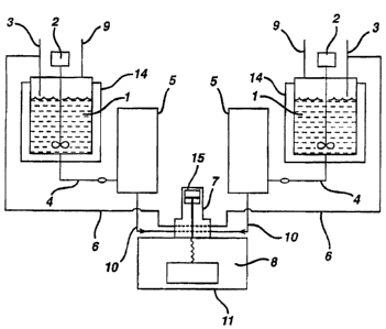
schematic of a typical RIM process is shown in Figures 1
and 2 for a two stream process. Typically, the RIM
process proceeds as follows:
Referring to Figure 1, the monomers (1) are
stored in separate reservoirs or tanks (14), usually
under nitrogen or dry air blankets (9). These tanks are
jacketed and equipped with stirrers (2) in order to
maintain the monomers at a specified temperature range.
The monomers are in the liquid state in these tanks.
A predetermined and precise amount of each
liquid component is drawn from each tank through an
inlet line (4) with a metering cylinder or pump (5) and
delivered to the mixing chamber, the mixhead (7), at
high pressure through connecting means (10). A
- 25 recirculation line (6) connects the mixhead with the
storage tank line (3) through which excess material can
be returned to the reservoir.
The high pressure is required to attain
material velocity and turbulence sufficiently high to
30 cause thorough mixing of the two monomers.
.' ,
l Before entering the mixhead, wherein the
monomers meet, they pass through small apertures in the
side wall of the mixing chamber. In a typical mixhead,
the mixing chamber is created by the pullback of a rod
(15), creating a cylindrical cavity. The orifices
impinge the high pressure fluid streams at 180 angle,
frequently in the rear portion of the cavity. The rod
is activated, at the conclusion of the impingement, and
moves forward to push the reacting fluid from the
chamber into a mold cavity (8), which is attached to the
mixhead (see Figure 2). The reactive material passes
through a gate (13) into the mold wherein the
polymerization is completed. Typically, to prevent
trapping of air inside the mold, the mold contains a
15 vent (12) which passes from the mold wall (11) to the
mold cavity (8).
The present inventors have found a means of
utilizing this RIM process for the manufacture of
contact lenses from IPN material. This methodology is
fast and efficient and is quite suitable for high speed
production. Moreover, the RIM process has the
capability to reduce or eliminate shrinkage related
defects in contact lenses. It permits the use of IPN's
for the preparation of hydrogels suitable for contact
lenses which have properties that are not achievable
either from acrylic polymers or urethane polymers
separately.
SUMMARY OF THE PRESENT INVENTION
Accordingly, the present invention is directed
30 to the process for preparing a contact lens comprising
g
1 (a) mixing a reactive mixture in a RIM machine
under conditions sufficient to initially form a mixture
of precursors for polyurea and polyacrylic networks
which upon curing forms an interpenetrating polymer
network, said reactive mixture comprising:
(i) an amine terminated chain extender
comprising a mixture of amines A and B, said amines
being present in about 20-60% by weight in said reactive
mixture,
10 wherein A is
)$0/\
~ IO ~ RIL
and B is
~2 ~ ( ~ R )f -
wherein f1 is an integer from 1-75;
R is an alkylene containing 3 carbon atoms and
each R is the same;
f is an integer between 1 and 150, inclusive;
R1o~ R1l, R12, R13 and R14 are independently
hydrogen or lower alkyl;
Z1 and Z2 are independently a chemical bond or
lower alkylene;
3o with A and B being present in relative weight
ratios ranging from 60/40 to about 100% A,
~:1'73~3
--10--
1 (ii) an organic di or polyisocyanate present
in sufficient quantities to react with said amine
terminated chain extender of (i),
(iii) an acrylic ester of the formula:
C~z _ _
~' ~ ~ O ~ 5 - ~,~ ~ L
O ~ ~
or
C~
R ~,--(R, ~ ~ R8) , ~V
wherein
m is an integer from 0 to 150;
R~ is hydrogen or lower alkyl;
Z3 and Zs are independently alkylene;
Z4 and Z6 are independently a chemical bond or
lower alkylene;
CH2
R4 is hydrogen, lower alkyl or -C-C-R5;
Rs is hydrogen or lower alkyl;
R6 and R~ are lower alkyl;
R7 is a lower alkylene, a chemical bond or -
CH2(OCH2CH2)q;
q is an integer between 0 and 200, inclusive;
and
p is an integer of 1 to 3;
,
said acrylic ester being present in about 10-50~ by
weight in said reactive mixture; and
(iv) a free radical initiator being present in
sufficient quantities to polymerize the acrylic ester of
(iii), forming therefrom a polyacrylic network;
wherein the ratio of polyurea to polyacrylic
ranges from about 60:40 to about 85:15;
(b) injecting said liquid interpenetrating
polymer network into a closed mold in fluid
commlln;cation with the RIM machine having a cavity
defining the shape of a contact lens under conditions
sufficient to gel and harden said liquid;
(c) removing the product of (b) from the mold;
(d) post-curing the product of (c) and
(e) immersing the product of (d) in a water or
an aqueous medium until equilibrium is reached to form a
contact lens in the form of a hydrogel.
BRIEF n~-SrRTPTION OF T~E DRAWINGS
Figure 1 is a typical schematic of the RIM
process.
Figure 2 is a schematic of a typical mold.
DET~TT-~n n~-Sr~TPTION OF T~E INVENTION
The interpenetrating polymer network prepared
by the present invention comprised of polyurea and
polyacrylic networks is described in co-pending
application having Serial Number 08/415,001, and
~ 1 7 ~
-12-
l entitled "Interpenetrating Polymer Network for Contact
Lens Product", the contents of which are incorporated
herein by reference. The IPN is completely homogeneous
and exhibits a single glass transition temperature.
The polyurea network is a network that is
formed from the spontaneous reaction of amines, i.e., an
amine terminated chain extender, with organic di- or
polyisocyanates in the presence of triamines.
The amines suitable for the present invention
are polymers having two or more terminal amino
functionalities or secondary amines or a combination of
a terminal amine and a secondary amine. The most
preferred amines are amino terminated polyethers.
Examples of the amines include poly(oxyethylene)
15 diamine, poly(oxypropylene) diamine, triethylene glycol
diamine, and the like.
The amine component is comprised of a mixture
of amines, a polyoxyethylene diamine and a
polyoxypropylene diamine. It has been found by the
present inventors that the balance of polyoxyethylene
diamine and polyoxypropylene diamine is very important
to the transparency and water absorption ability of the
IPN elastomers. The presence of poly(oxyethylene)
amines in the formulation is necessary to permit the
25 hydrogel to absorb water. As the content and molecular
weight of the polyoxyethylene amine increases, the
resulting hydrogels absorb more water. Unfortunately,
the transparency suffers as the poly(oxyethylene) amines
tend to crystallize. The presence of poly(oxypropylene)
30 amines in the formulation is necessary to obtain
transparent hydrogels.
. ,
f
~L 73~
-13-
1 The poly(oxyethylene) amines used in the
present invention have the formula:
5 ~ .~ J~
R ~ o ~ RIL
0
herein Rl3~ R14~ Rlo, Rl1, R12, f, Zl and Z are
as defined herein.
It is preferred that f is 30-70.
A preferred embodiment thereof has the
formula:
~ Z ~ O ~
_ ,~
The poly(oxypropylene) amine used herein
preferably is of the formula:
~2 ~ (O ~ R)
wherein R is an alkylene chain containing 3 carbon atoms
and each R is the same and f1 is an integer of 1-50.
The preferred R is isopropylene and the preferred values
30 of f, is 1-30 and f is 30-70.
. , i
f
~3~S
1 In the preferred embodiment of the present
invention, the mixture of amines preferably comprises a
poly(oxyethylene) diamine of the formula I:
H z ~ z
_ f
wherein f is an integer of 30-70 and a
poly(oxypropylene) diamine of the formula lB:
CH~
~z~-CH--CH~ ~o~CH C~ ~H~ IB
wherein f, is an integer of 1-30.
It is preferred that the amine be present in
about 20-60% by weight in the starting monomeric
mixture. The preferred relative weight ratio of IA and
IB range from about 60/40 to about 100% A, respectively.
It is to be noted that unless indicated to the
contrary, the percentages and ratios herein are by
weight.
The organic di or polyisocyanates used to form
the polyurea network of the present invention are
3O represented by the formula Q(NCO)t wherein t is
preferably 1-4 and Q is an hydrocarbyl group, i.e., an
~`
'` l r~
1 organic radical consisting solely of carbon atoms and
hydrogen atoms. Q may be aliphatic, alicyclic,
aromatic, or combination of any of these groups, such as
aliphatic-aromatic group, aliphatic-alicyclic group, and
the like. The Q group may be unsubstituted or
substituted with lower alkyl, hydroxy, lower alkoxy. It
is preferred that the isocyanate is aliphatic. In a
preferred embodiment, it is preferred that Q contains
from 3-26 carbon and more preferably from 4-20 carbon
atoms and most preferably from 6 to 14 carbon atoms. In
the above formula, t is an integer greater than 1 and
preferably 2-4. Representative examples of the
isocyanates include tetramethylene diisocyanate;
hexamethylene diisocyanate; trimethylhexamethylene
diisocyanate; dimer acid diisocyanate; isophorone
diisocyanate; diethylbenzene diisocyanate; decamethylene
1,10-diisocyanate; cyclohexylene 1,2-diisocyanate,
cyclohexylene 1,4-diisocyanate, 2,4- and 2-6 tolylene
diisocyanate; 4,4-diphenylmethane diisocyanate; 1,5-
20 naphthalene diisocyanate; dianisidine diisocyanate;toluidine diisocyanate; 4,4' methylene-
bis(cyclohexylisocyanate), neopentyltetraisocyanate, m-
xylylene diisocyanate, tetrahydronapthalene-1,5-
diisocyanate and bis-(4- isocyanatophenyl) methane; and
25 the like.
The most preferred isocyanate is 4,4'
methylene- bis(cyclohexylisocyanate). Other preferred
isocyanates are trimethyl hexamethylene diisocyanate and
isophorone diisocyanate.
3o The isocyanates utilized in the present
invention react with the amines to form the polyurea
9 ~
-16-
1 network. The isocyanates are present in such amounts as
to react with the amines present. In the preferred
embodiment the diisocyanate is present in 15-50% by
weight of the starting monomeric mixture, and preferably
in the amount of 25-40% by weight.
The reaction of the isocyanate with the amine
is spontaneous, and thus no catalyst is needed for the
polyurea formation. Moreover, the reaction is
exothermic. The heat generated from the amine-
isocyanate reaction can accelerate the free radicalinitiated polymerization of the acrylate, the other
network of the interpenetrating network polymer prepared
by the present invention.
The other network is comprised of an acrylic
ester. The acrylic esters suitable for the present
invention are polymerizable polyacrylate derivatives of
polyhydric alcohols.
The acrylic esters are the ester derivatives
of acrylic acid of the following formula:
o
CHz = C - C - OH
R3
wherein R3 is hydrogen or lower alkyl. It is to be
25 noted when R3 is methyl, the acid is methacrylic acid.
Monohydric alcohols and polyhydric alcohols
having a molecular weight of less than 7,000 daltons and
being amenable to esterification using the acrylic acids
described hereinabove are suitable for use in the
30 present invention. Preferred alcohols include
monomethoxypolyethylene glycol, ethoxyethylene glycol,
. , i
~ 1 7 3 i~
-17- --
l ethylene glycol, diethylene glycol, triethylene glycol,
poly(oxyethylene) glycol, poly(oxypropylene) glycol,
poly(oxypropylene)-triol, glycerol, trimethylol ethane,
trimethylol propane, 1,4-cyclohexane diol,
pentaerythritol and the like.
Since the polyhydric alcohols contain more
than one hydroxy group, more than one acrylic unit can
esterify to the polyhydric alcohols. Thus, acrylic
esters of the present invention include mono-,di-, and
polyacrylate derivatives of the alcohols described
hereinabove, especially methacrylate derivatives
thereof.
The acrylic esters useful in the present
invention are of formulae III or IV:
CHz
~ 3 ~ 0 ~ 5
O ~
C~
R~--(R~ ~~R8) IV
O P
3o
wherein
v~ ~
-18-
1 R3 is as defined hereinabove;
m is an integer from 0 to S0;
Z3 and Zs are independently lower alkylene;
Z4 and Z6 are independently a chemical bond or
lower alkylene;
6H2
Z4 is hydrogen, lower alkyl or - C - C - R5 ;
o
Rs is hydrogen or lower alkyl;
R6 and R~ are lower alkyl;
p is an integer of 1 to 3;
R7 is a lower alkylene a chemical bond or
CH2 ( OCH2 ) q; and
q is an integer of 0 to 200, inclusive.
As used herein, the term lower alkyl when used
alone or in combination with other groups refers to an
alkyl chain containing 1 - 6 carbon atoms. The alkyl
groups may be straight chained or branched. Examples
include methyl, ethyl, propyl, isopropyl, butyl, sec-
butyl, t-butyl, isobutyl, pentyl, isopentyl, neopentyl,
hexyl, and the like. It is preferred that the alkyl
group contains 1 - 3 carbon atoms.
As used herein, the term alkylene refers to a
25 hydrocarbyl group derived from an alkyl group by
dropping a hydrogen from the formula. The alkylene is
bonded to two other groups in the main chain. Examples
include -CH2- ~ -CH2-cH2-, -cH2-cH2-cH2-, -CH-CH2-,
3O and the like. It is preferred that the alkylene groups
contain 1 - 3 carbon atoms.
~ ~ ~i' 3 ~ 3~
--19-- .. .
1 It is most preferred that R3, R5 and R8 are
alkyl having 1-3 carbon atoms, especially methyl.
Preferred values of R6 and R8 are lower alkyl
having 1-3 carbon atoms. Preferred R6 is ethyl and
preferred R8 is methyl. It is preferred that R, is
methylene.
Preferred values of R, are hydrogen, lower
alkyl having 1-3 carbon atoms, and IlH2
-C - C - R5
o
especially methacrylate.
It is preferred that m is 0 to 30, and
especially 0 to 20.
Preferred values of Z4 and Z6 are independently
chemical bonds and alkylene groups having 1-3 carbon
atoms. It is preferred that Z3 and Z5 are independently
alkylene groups containing 1-3 carbon atoms. It is also
preferred that Z3 is the same as Z6~ and Z~ is the same
as Zs~
Preferred values of q are 0 to 100, more
preferably 0 to 50 and most preferably 0 to 25.
A preferred embodiment of Formula III has
formula III A:
C~L
Il ~ _ IIIA
R~ o~ O~
3o
~73~5
-20-
1 wherein m, R3, and R4 are as defined hereinabove. It is
preferred that R4 is hydrogen or lower alkyl, R3 is lower
alkyl, especially methyl and m is 0-20.
Another preferred acrylate monomer of Formula
III is the diacrylate of the formula:
Cl~ C~L
~R5 III B
_ _ n O
wherein Rg is hydrogen or lower alkyl and R5 is as
defined hereinabove, preferably methyl, and n is 0 to
30.
The acrylic esters are present in about 10 to
about 50% by weight in the starting monomer mixture, and
more preferably from about 15% to about 35% by weight.
It is preferred that the acrylic ester
consists of a mixture of acrylic monomers. The first
acrylic monomer is comprised of an acrylate of Formula
IIIA, while the second acrylic monomer comprises a
compound of Formula IIIB or IV, or mixtures thereof.
The first and second acrylic monomers are present in
relative weight ratios ranging from about 80/20 to about
95/5, respectively.
Examples of the acrylic monomers are
methacrylates which include hydroxyethyl methyacrylate
(HEMA) of the formula:
C~L
3 ~C J~--~~C~
-21- -
1Another preferred monomethacrylate is poly
(ethylene glycol) monomethacrylate having the formula:
CU2
5~3C J ~ ~ - O ~ oH
O ~
wherein m is an integer from 0 to 20.
lOAnother preferred monomethacrylate is a poly
(propylene glycol) monomethacrylate having the formula:
U~c ~f ~ /m
wherein m is an integer from 0 to 20.
A preferred dimethacrylate is poly (ethylene
glycol) dimethacrylate, having the formula:
C~L .-- -- ~U2
~,C~` o~~~~C~,
25O ~ -n O
wherein n is an integer from 0 to 20.
Another preferred dimethacrylate is poly
3o (propylene glycol) dimethacrylate having the formula:
~ r6~ 3 ~ ~ 5
-22- -
.
CUL C~3 \ C~z
~3CJ~~~--~
5~ C~3 ~ /n O
wherein n is integer from 0 to 20.
A preferred trimethacrylate is trimethylol
propane trimethacrylate having the formula:
C-~t - cuzL
\~\ C~ \
15O~ CU~
~ O ~ 3
To form the acrylic network, the acrylic
esters described hereinabove are reacted with a a free
radical initiator under polymerization conditions. Free
radical polymerization initiators of the type commonly
used in polymerizing ethylene compounds are suitable for
use in the present invention. They include such
representative initiators as benzoyl peroxide, t-butyl
25 hydroperoxide, t-butylperoxide, azo-bis
(isobutyronitrile), 2, S dimethyl-2, 5-di(2-ethyl
hexanoylperoxy) hexane, l,l-di(t-butylperoxy) - 3,3,5-
trimethylcyclohexane, di-t-butyl-diperoxyphthalate,
peroxides, hydroperoxides, mixtures of peroxides and
30 hydroperoxides (Lupersol DDM-9), l,l'-azobis-(l-
cyclohexanecarbonitrile), 2,2'-Azobis [2-(2-imidazolin-
h ~
..
-23-
1 2-yl)propane] dihydrochloride, 2,2'-Azobis (2,4-
dimethylvaleronitrile) 2,2' Azobis (4-methoxy-2, 4-
dimethylvaleronitrile), and the like.
The free radical initiators are present in
amounts ranging from greater than 0% to about 2% by
weight of the reaction mixture, and preferably from
0.01% to about 1%, and more preferably from 0.02% to
about 0.5%, and most preferably from 0.03~ to about 0.1%
of the mixture.
In addition, a triamine is present in the
monomeric mix. The triamines are cross-linkers in the
polyurea-acrylic IPNs. They also are used as
compatibilizers in the polyamine mixture, especially if
the RIM machine is not equipped with a mixing device.
15 To ensure that the mixture of the polyoxyethylene
diamine and the polyoxypropylene diamine remain
homogeneous, it is preferred that the diamine mixture is
constantly stirred. If the IPN is prepared in the
absence of a stirring device, such as in some Mini-Rims,
20 then a cross-linker, i.e., the triamine, is added to
ensure the homogenity. The triamines are present in
amounts ranging from about 30 to about 50% of the total
amine equivalents. It is preferred that the triamines
be present in amounts ranging from 1% to about 20% by
25 weight and more preferably from about 3-5% by weight.
Examples of triamines include diethyltriamine, poly-
(oxypropylene) triamine and the like.
These reactive components, the polyamines, the
isocyanates, the acrylic esters, the free radical
initiator, the triamines are intimately mixed together
initially in a typical reaction injection molding
, 3 ~ ~
..
-24-
1 apparatus. The reservoirs and thus the streams of the
reactant components are set up so that interfering side
reactions, such as those leading to discolorations,
precipitation and polymerization are eliminated.
At a minimum in the RIM process, at least two
streams of reactive components are delivered to the
mixhead from each reservoir containing the reactive
components. In this embodiment containing two streams
of components, a mixture of the polyamines is stored in
one of the reservoirs, as a li~uid. If the triamine
cross-linking agent is present, it is also stored in
this first reservoir, and together, both the polyamines
and triamines are delivered to the mixhead as a first
stream. A second reservoir contains a mixture
comprising the acrylic esters, the isocyanate and the
free radical initiator which mixture is delivered to the
mixhead as a second stream of components. The materials
in the reservoir should be maintained at temperatures
that insure stability of the materials as well as
20 maintenance of their fluidity. Thus, the reservoirs may
be maintained at or near room temperature or be slightly
heated. In a preferred embodiment of the two stream
mixture, it is preferred that the first reservoir is
slightly heated to temperatures of about 75-100C, and
25 more preferably 80C, while the second stream is
maintained at room temperature. A precise and
predetermined amount of liquid, in accordance with the
amounts described hereinabove, is drawn from each tank
with a metering cylinder or pump and is delivered to the
30 mixhead compartment.
-25-
,
1 Of course, the RIM apparatus may be set up
with more than two reservoirs and thus more than two
streams of material can be delivered to the mixhead.
Although as a theoretical matter, an infinite number of
streams of reactive components are possible, as a
practical matter, there should be no more than 8 streams
and more preferably no more than 5 streams. Upon
investigation, the amines appear to react with the other
non-amino components. Thus, the amines should be stored
in their own individual reservoirs or may be stored
together in one reservoir. The other components, i.e.,
the acrylate, the isocyanate and the free radical
initiator may be stored together or in individual
reservoirs. Thus, an embodiment of the present
inventions is a three stream system which comprises the
amines as one stream, the acrylic esters as one stream
and the free radical initiator and isocyanate as the
third stream, while an embodiment of a four stream
system comprises the amines as two separate streams, the
acrylic ester as a third stream and the isocyanate mix
with the free radical initiator as the fourth stream.
It is important in the RIM process that the quantity of
material to be dispensed from each stream be of similar
quantity.
Regardless of the number of reservoirs, a
predetermined amount of each component is removed from
each reservoir and placed into the "stream" and
delivered to the mixhead compartment, wherein the
various streams meet. The various streams are impinged
30 at the mixhead compartment at pressures sufficient to
insure intimate contact and mixture of the reactive
-26-
l components. Typically, they are mixed by impingement at
the mixhead at pressures ranging from about 400 to about
3000 psi, and more preferably from 1500 to about 3000
psi.
It is at the mixhead compartment wherein
polymerization to form the IPNs of the present invention
initially occurs. However, the polymerization is
completed in the contact lens mold assembly, which is
connected to the RIM by a runner channel which passes
through a sprue into the lens mold assembly. The
opening of the sprue is controlled by a gate, which
opens and closes.
The polymerization is generally carried out at
temperatures from about room temperature to about 145C.
It is generally preferred to initiate the polymerization
at relatively low temperatures such from about 45C to
80C and then increase the temperature to about 110 to
130C.
Usually, the polymerization is conducted under
an inert nitrogen atmosphere in order to exclude the
oxygen from the atmosphere which has the deteriorating
effects on the formation of polymers of the present
invention.
The contact lens mold assembly is in fluid
25 communication with the mixhead and as indicated
hereinabove, is connected to the RIM by connecting means
which passes through a sprue into the lens mold
assembly. The mold assembly (hereinafter used
interchangeably with "mold") that is used is one that is
typically used in preparing contact lens. In a
preferred embodiment, the mold assembly comprises two
ï 3 ~ ~3 5
-27-
1 mold halves useful in the production of a contact lens
(i.e., a lens having ready to wear dimensions or a lens
needing to be swelled (hydrated) to its final ready to
wear dimension). Each mold half has a central curved
section defining a concave surface, a convex surface and
having the reduced dimensions (i.e., for an unswelled
lens, 12.7mm in diameter versus 14.0-14.4m for a swelled
lens) of the front or back curve, respectively of a
contact lens produced in the mold assembly, said mold
assembly having an annular flange integral with and
surrounding said circular circumferential edge and
extending therefrom in a plane normal to the axis of
said concave surface. When preparing the contact lens,
the two mold halves are held together by connecting
15 means, such as a clamp, spring or bolt to form a mold
assembly, said mold assembly comprising a front mold
half and a back mold half in contact therewith, thereby
defining and enclosing a cavity therebetween. It is the
concave surface of the front mold half which has the
curvature of the front curve of the contact lens to be
produced in said mold assembly and is sufficiently
smooth so that the surface of a contact lens formed by
the polymerization of the IPN in contact with said
surface is optically acceptable. It is the convex
25 surface of the back mold half which has the curvature of
the bac~ curve of the contact lens to be produced in
said mold assembly and is sufficiently smooth so that
the surface of the contact lens formed by the
polymerization of the IPN in contact with said surface
30 is optically acceptable.
3 ~
-28- -
1 The mold material is made of glass, stainless
steel, aluminum or other material commonly employed as
molds for contact lenses; it is preferred that the mold
material be aluminum or stainless steel; especially
polished stainless steel.
As described hereinabove, the mold assembly
has a central cavity in the shape of contact lens. The
cavity may have variable thickness as reguired to
provide the correct dioptric power. The variable
thickness may be calculated using optical formulas
familiar to those skilled in the art. The central
thickness of the cavity ranges from about 0.00039 to
0.0118 inches.
It also contains a central sprue, which
opening connects the mold to the RIM machine and through
which a runner channel connecting the RIM machine and
the mold assembly passes. The mold assembly also
contains a plurality of vent apertures, positioned at
various points on the surface of the mold assembly and
extending through the cavity. As described hereinbelow,
the vent serves to release excess reacting liquid and to
permit the advancing flow of liquid polymerizing
material to expel ambient atmosphere from the mold.
In a preferred embodiment of the present
invention, the mold assembly has a central sprue and a
symmetrical mold cavity of thickness of about 0.00039 to
0.0118 inches and more preferably about 0.0018 to about
0.0039 inches. The mold contains vent lines, located at
each of the four mold edges.
3o
~ 3
-29- -~
1 In another embodiment, the mold cavity
possesses a dual thickness cavity, wherein the cavity
thickness varies form 0.004 inches to 0.032 inches.
In still another embodiment, the mold assembly
consists of a mold cavity machined into one surface of
the mold opposite to the sprue. It contains vent lines
within a few inches, such as 4-6 inches, of the sprue.
Such vents in the mold permit the air to escape from the
cavity before the material can harden, thereby
eliminating any entrapment of air in the lens.
It will be clear to those skilled in the art
that other modifications in the mold assembly and mold
can be utilized, and these other modifications are
within the scope of the present invention.
As indicated hereinabove, the polymerization
is initiated at the mixhead compartment. The pressure
of injection forces the resulting liquid product, a low
viscosity reacting liquid, through the runner system
across the mold cavity until eventually the mold is
filled with the initially polymerized product.
Polymerization continues in the mold, where it is
completed and the solid interpenetrating polymer network
is formed.
Without wishing to be bound, it is believed
25 that the location of the vents affects the ability of
the present process to reduce or eliminate shrinkage
related defects. More specifically, the first injected
material will gel at a point in the mold after the
cavity, i.e., in the vents. When the material gels, it
30 will no longer flow. This creates a back pressure in
the cavity. As the material in the cavity reacts, its
~i7~
-30-
1 volume decreases, thereby reducing the pressure in the
cavity. Additional material is forced into the cavity
filling the voids, thereby, reducing shrinkage related
defects.
It is also believed that there is an
additional mechanism taking place. Without wishing to
be bound, it is believed that this mechanism is active
in the RIM process. Because reaction begins at the
moment of injection, a substantial fraction of the
material has reacted before it reaches the cavity.
Therefore, only a small amount of residual shrinkage
occurs in the cavity.
The RIM process also reduces shrinkage related
edge defects. Without wishing to be bound, it is
believed that the edges of the ocular lens may be formed
in a positive manner by the closing of the optical
cavity by an annular moveable gate. The timing of the
closing of the gate may allow edge formation after a
suhstantial portion of the shrinkage has occurred,
thereby reducing shrinkage related edge defects.
After the polymerization process is completed,
the two halves of the mold are separated during a
demolding step. The mold is opened by prying means,
either manually or utilizing an instrument, and the IPN
film is removed. External mold release agents,
especially water-soluble mold release agents known in
the art, may be utilized. Examples include such mold
release agents as Frekote or Hysol Ac 4368, which may be
applied to the surface of the mold to facilitate
30 demolding. Alternatively, the inner surface of the mold
may be lined with polyethylene. The polyethylene film is
~173~5
.
-31-
1 easily removed from the mold surface following injection
of the molded elastomers. To help facilitate the
release even further, the mold containing the
polyethylene film is slightly heated to temperatures of
50-70C.
Another demolding process utilizes water,
wherein it is incorporated as an inert diluent into the
acrylic monomer stream at an effective concentration for
demolding to occur at temperatures between 50C-70C
inclusive. It is preferred that the water be present at
a concentration of about 3 to about 7 weight percent and
more preferably about 5 weight percent.
The demolded IPN film may be post-cured by
heating the film (lens) at temperatures ranging from
15 about 60C to about 125C, and more preferably from
about 75C to about 110C and most preferably at 100C
to complete the polymerization.
Finally, the shaped IPN film is immersed in
water or an aqueous medium, such as saline solution,
20 until equilibrium is achieved. When swollen in the
water or aqueous medium, the polymeric materials are in
the form of hydrogels which are particularly suitable
for use in making extended wear contact lenses. The
water content of the hydrogel is greater than or about
25 30% by weight (water content is measured as weight of
water based on weight of hydrogel).
The process of the invention makes possible
the preparation of high quality contact lenses by a
novel, simple economical procedure which avoids
3O difficulties encountered in prior art procedures. The
RIM process has the capability to reduce and eliminate
~73~
-32-
1 shrinkage related defects in the contact lens. It also
is fast and efficient and economical. As described
above, a low viscosity liquid is injected into the mold.
Thus, a lower pressure molding machine is suitable for
the operation. Also, less expensive molds are required
because of the lower pressure requirements. The use of
smaller machines and less expensive molds result in
lower costs. The present process also allows the use of
IPN's for the preparation of hydrogels suitable for
contact lens of the highest qualities and which is not
achievable alone by its constituent parts, the acrylic
polymers or urethane polymers separately.
The contact lens produced by this process has
outstanding physical properties. It has high tensile
and shear strength, and exhibits excellent mechanical
properties. It has high wettability and high
permeability to oxygen. The contact lens produced by
this process permits visible light transmittance
therethrough. The contact lens produced by this method
is homogenous which is confirmed by the single glass
transition temperature exhibited by the contact lens
material of the present invention.
The following examples will serve to
illustrate the principles and scope of the present
invention.
In the following examples, various
abbreviations are utilized. The table below contains
the abbreviations to which reference is made in the
examples.
3o
h 1 i 3 ;~ ~ 5
--33-- - -
OODB CHeMICAL NAME ~OL. ~T.
Jeffamine ED-900 Poly(oxyethylene) diamine 1179
Jeffamine ED-2000 Poly(oxyethylene) diamine 2277
Jeffamine D-2000 Poly~oxy~opylene) diamine 2000
Jeffamine T-403 Poly(o~yp~op~lene) ~i r i ne 440
Jeffamine EDR148 TrLethylene glycol dir i nP 148
DETA Diethylene triamine 103
Desmodur W 4,4'-Methylene-bis-cyclohexyl- 262
isocyanate, Hl2MDI
HEMA Hydroxyethyl methacrylate 103
PEGMA Polyethylene glycol 306
monomethacrylate
TEGDMA Triethylene glycol dimethacrylate 286
PEG (600)DMA Poly (ethylene glycol-600) 700
dimethacrylate
L-256 Lupersol-256
BPO Benzoyl peroxide 242
3o
3 ~ ~
34--
EXAMPLE 1
A blend was made of 589. 5 parts ED-900, 400
parts D-2000, 155.4 parts EDR-148 and 34.3 parts DETA.
This blend was called Stream 1. A second blend was made
5 of 589.5 parts Hl2MDI, 560.1 parts HEMA, 29.48 parts
TEGDMA and 11.9 parts L-256. This blend was called
Stream 2. The streams were placed in the material
reservoirs of a two stream laboratory scale RIM machine.
Stream 1 was heated to about 80C to maintain fluidity
of the materials. Stream 2 was maintained at room
temperature to insure stability of the materials. The
streams were mixed by impingement at a pressure of 2500
psi. and injected into a two piece aluminum mold. The
mixing ratio was 1.010 parts Stream 1 for each part of
Stream 2. The injection time was 0.20 seconds. These
conditions produced about 20 gm. of polymer in which
both networks were separate and simultaneously produced.
The mold consisted of two aluminum plates.
One of the plates was machined such that it had two
compartments. One compartment was designed to produce a
film 100 microns thick. The other compartment was
designed to produce a film 800 microns thick. The mold
was held together by bolts. The mold was heated to
100C in an external oven. When the mold reached 100C,
it was attached to the RIM machine. The material was
post-cured in the mold for 10 minutes following the
injection molding operation.
The mold was opened manually and the
elastomeric film was removed from the mold. The
30 demolded film was post-cured for one hour in an oven at
- h~ ï3r3
-35-
1 100C. The film was converted to a hydrogel by
immersion in a buffered saline solution.
The material produced was a clear IPN hydrogel
of 75~ (weight) urea component and 25% (weight)
methacrylic portion. Following hydration, the material
had the following properties:
Water content 34%
Modulus 262 psi
Tensile strength 300 psi
Elongation at break 238%
This material is suitable for use as a contact lens.
3o
;~
. , i
3~5
-36-
1 EXAMPLES II to V
A series of IPN elastomers were prepared using
the methods of Example I. The formulations and
properties are shown in Table II.
TABLE II
EXAMPLE ¦ II ¦ III ¦ IV ¦ V
Stream 1
ED-900 589.5 589.5589.5 471.6
ED-2000 - - - 227.9
D-2000 200 - 400 400
EDR-148 155.4 155.4229.4
DETA 34-3 34-3
Stream 2
H~2MDI 563.3 537.1 589.5 1133.8
HEMA 483.6 412.68 566.9
PEGMA - - - 454.0
TEGDMA 25.4 21.7 29.8 23.9
L-256 10.2 8.7 11.9 9.6
UREA/ACRYLIC RATI0 75/25 75/25 75/25 75/25
STREAM l/STREAM 2 0.90 0.76 1.02 1.37
Water content 37.5 47.1 33.1 60.8
Modulu- (psi) 218 87 NA 133
Tensile strength (psi) 263 101 110 81
25 Elongation at break ~96) 206 130 169 101
Appearance clear opaquehazy clear
The materials of Example II and Example V are suitable
for contact lens use.
3o
2:~73~
-
-37-
1 EXAMPLE VI
A blend was made of 471.6 parts ED-900, 228
parts ED-2000, 400 parts D-2000 and 34.3 parts DETA.
This blend was called Stream 1. A second blend was made
of 314.4 parts Hl2MDI, 454.0 parts HEMA, 23.91 parts
TEGDMA and 9.6 parts L-256. This blend was called
Stream 2. The streams were placed in the material
reservoirs of a two stream laboratory scale RIM machine.
Stream 1 was heated to about 80C to maintain fluidity
of the materials. Stream 2 was maintained at room
temperature to insure stability of the materials. The
streams were mixed by impingement at a pressure of 900
psi and injected into a two piece aluminum mold. The
mixing ratio was 1.37 parts Stream 1 for each part of
Stream 2. The injection time was 0.25 seconds. These
conditions produced about 25 gm. of polymer in which
both networks are separate and simultaneously produced.
The mold used for this example was described
in Example 1.
The mold was opened manually within one minute
of injection and the elastomeric film was removed from
the mold. The demolded film was post cured for about 40
minutes in an oven at 100C. The film was converted to
a hydrogel by immersion in a buffered saline solution.
The material produced was a clear IPN hydrogel
of 75% (weight) urea component and 25% (weight)
methacrylic portion. Following hydration the material
had the following properties:
3o
.; , i
~ ~7 ~. O 3 ~
-
-38-
1 Water content 50%
Modulus 93 psi
Tensile strength 91 psi
Elongation at break 239%
This material is suitable for use as a contact lens.
3o
>,
.~ , i
~ it-~3~3~
-39-
1 EXAMPLES VII TO IX
A series of IPN elastomers were prepared using
the methods of Example VI. The formulations and
properties are shown in Table III.
TABLE III
EXAMPLE ¦VII ¦ VI~I ¦ IX
Stream 1
ED-900 353.7 471.6 471.6
ED-2000 227.9 455.8 455.8
D-2000 400 200 200
DETA 34.3 34 3 34 3
Stream 2
H~MDI 288.2 314.4 314.5
15 HEMA 408 463 463
TEGDMA 21.5 24.3 24.3
L-256 8.6 19.4 9.8
UREA/ACRYLIC RATIO 75/25 75/25 75/25
STREAM l/STREAM 2 1.35 1.37 1.39
20 Water content 40.1 43.1 42.2
Moduluq (pqi) - 254 245
Tensile Strength (p9i) 141 292 221
Elongation at brea~ (%) 260 165 221
Appearance clear clear clear
The materials of Examples VII, VIII and IX are suitable
for contact lens use.
3o
~73~
-40-
1 EXAMPLE X
A Hi-Tech three system RIM machine was used
for this example. The machine was fitted with an Edge-
Sweets four component mixhead. The mixing was by
impingement.
The chemical system consisted of eight
separate chemicals. The materials were blended as
follows:
Stream 1
870.9 gm Jeffamine ED-900 Poly(oxyethylene) dir ine MW 1179
420.9 gm Jeffamine ED-2000 Poly(oxyethylene) di~mine MW 2277
738.7 gm Jeffamine D-2000 Poly(o~y~Lopylene) ~i~ ine MW 2000
63.5 gm DETA Diethylene Triamine
(Jeffamine is a trademark of the Texaco Chemical
Company~
stream 2
3502 gm HEMA Hydroxyethyl Methacrylate
72.4 gm TMPTMA Trimethylolpropanetrimethacrylate
Stream 3
3140 gm H2i~i~I 4,4'-methylene bis (cyclohexyl
isocyanate)
96.6 gm Benzoyl peroxide
The process conditions were:
stream Pressure Orifice Flow Rate Viscosity
1 2700 psi 0.75mm 99.3gm/sec52cps
2 lsoo psi 1.25mm 42.30gm/~ec6cps
3 1900 psi 0.50mm 28.4gm/sec24cps
Stream 1 was split and injected in two
separate ports. The ports were chosen to be 90apart.
This gave direct impingement of one-half the amine and
3 the isocyanate streams.
~7~(~9~
-41-
1 The inject~on time was set at 0.03 sec. and a
shot weight of 13.6 gm obtained.
The injection head of the RIM machine was
affixed to a hardened steel mold. The mold had a
channel 2mm wide and 4mm deep leading to a contact lens
shaped cavity. The injection of the formulation into
the mold produced a contact lens.
3o
A
3 ~ ~ ~
-42-
1 EXAMPLES XI, XII, XIII
Examples XI, XII, XIII were duplicates of
Example X except that the flow rate of Stream 2 was
changed to change the ratio of urea to acrylic fractions
of the IPN's. The flow rates of Stream 1 and Stream 3
were adjusted to obtain a constant shot size. The
orifice size was controlled to maintain the pressures of
Example X.
Example XI XII XIII
Stream 1 Flow rate 104.0 78.3 92.8
(gm/~ec)
Stream 2 Flow rate 33.2 66.7 50.8
(gm/~ec)
Stream 3 Flow rate 29.7 22.4 26.5
(gm/~ec)
UREA/ACRYLIC RATIO 80/20 60/40 70/30
When these formulations were injected into a
heated mold with a contact lens shaped cavity with an
annular gate, a contact lens was formed.
3o
3~5
.
--4 3--
EXAMPLES XIV, XV, XVI
Examples XIV, XV, XVI, were duplicates of
Example XI, XII, and XIII except that the flat plate
mold of Example I was used.
Example XlV XV XVI
Stream 1 Flow rate 120.2 78.3 92.8
(gm/sec)
O Stream 2 Flow rate 38.4 66.7 50.8
(gm/sec)
Stream 3 Flow rate 34.4 22.4 26.5
(gm/sec)
UREA/ACRYLIC RATIO 80J20 60/40 70/30
The resulting materials are useful as contact
lenses.
3o
,
., ,. i
21~i33~
. .
-44-
1 The above preferred embodiments and examples
are given to illustrate the scope and spirit of the
present invention. These embodiments and examples will
make apparent to those skilled in the art other
embodiments and examples. These other embodiments and
examples are within the contemplation of the present
invention. Therefore, the present invention should be
limited only by the appended claims.
3o
,