Note: Descriptions are shown in the official language in which they were submitted.
2173197
DOCKET: 1678
r~ N~n~
8URGICAL ~ .' APPARATU8
Technical Field
This application relates to a surgical cutting
instrument, and more particularly to a surgical cutting
instrument having a chamber for storing the cut tissue
portions.
Backqround of Related Art
Surgical instruments for cutting body tissue are
well known. One type of instrument has a pair of scissors
type jaws in which either both jaws move or one jaw moves
relative to the other fixed jaw in a scissors like fashion,
i.e. at an angle to the longitll~; nA 1 axis of the
instrument. An example of this scissors type instrument is
disclosed in U.S. Patent No. 4,994,024 to Falk. Another
type of cutting instrument, especially useful in orthopedic
procedures for cutting hard tissue or bone, has a cutting
blade which is slidable longitudinally in either a distal
or proximal direction to sever the body portion. Examples
of this type of instrument are disclosed in U.S. Patent No.
5,106,364 to Hayafuji et al., U.S. Patent No. 4,850,354 to
McGurk-Burleson et al., U.S. Patent No. 5,226,910 to
Kajiyama et al., and U.S. Patent NO. 4,282,884 to Boebel.
It is also recognized that as these cutting
instruments dissect the body tissue, it is advantageous to
remove the tissue portions as they are dissected or to
store the dissected tissue portions in the instrument.
This is especially the case in endoscopic surgical
procedures. Endoscopic (minimally invasive) surgical
procedures are performed under visualization through either
2173197
- small access ports or directly through small incisions in
the body. Therefore, if the dissected body tissue is not
removed as it is dissected, the instrument needs to be
withdrawn from the surgical site each time a tissue portion
is cut, the tissue portion needs to be manually removed
from the instrument, and then the instrument needs to be
reinserted to the surgical site. These steps need to be
repeated until the entire tissue section is removed. This
repeated re-insertion of the instrument can be very time
consuming, and therefore more expensive, especially in
endoscopic procedures, because the surgery is being
performed at a remote surgical site. The repeated
insertion can also cause complications in endoscopic
procedures where access to the surgical site is difficult
such as in endoscopic discectomy.
As noted above, the advantages attendant removing
or storing the dissected body tissue portions are well
known. One way of continuously removing the tissue portion
as it is dissected is by utilizing suction. One example of
the use of suction is disclosed in U.S. Patent No.
4,589,414 to Yoshida et al. In Yoshida, a cutting member
slides longitudinally in a distal direction to cut body
tissue positioned in the opening in the instrument and the
cut tissue is withdrawn through a suction channel in the
inner tube. U.S. Patent No. 5,007,917 to Evans discloses a
rotatable cutting blade for cutting tissue and a suction
tube for removing the tissue. The aforementioned patent to
Falk discloses a vacuum extraction channel for use with a
scissors type cutting instrument.
U.S. Patent No. 4,282,884 to Boebel, identified
above, has a storage chamber for the cut tissue. The punch
assembly is slid in a proximal direction, and the punched
out tissue portion is pressed into a tubular receiver
member and stored therein. At the end of the procedure,
the tissue portions can be removed from the receiver
member.
The need exists for an improved cutting
instrument for storing dissected tissue portions for
2173197
removal at the end of the procedure. Such instrument would
advantageously be configured to force the tissue sections
into the storage chamber to prevent clogging and allow for
-maximum use of the space in the chamber. The instrument
would also advantageously enable easy access and removal of
the tissue sections at the end of the procedure.
SU~ARY
A surgical apparatus for cutting and storing
sections of body tissue is provided comprising a housing
having a handle assembly, an elongated outer tube ext~n~ing
from the handle assembly, and a cutting tube positioned
within the outer tube and movable in response to actuation
of the handle assembly between a retracted position and a
distal position to cut body tissue. The cutting tube has a
chamber formed therein for storing the cut tissue sections.
An anvil may be positioned at a distal end of the outer
tube for forcing each cut tissue section proximally into
the chamber of the cutting tube as the cutting tube is
advanced to cut the body tissue. The outer tube preferably
has a window at a distal end to receive the body tissue and
the anvil is positioned distally of the window.
A plug or end cap assembly may be mounted at the
proximal end of the cutting tube and is removable therefrom
after the cutting tube is removed from the outer tube to
access the cut tissue sections.
The plug assembly preferably includes a plug and
a ret~ining member having a pair of ears extending into a
pair of notches in the cutting tube such that pulling on
the plug when the cutting tube is positioned within the
outer tube cams the ears further into engagement with the
notches to prevent removal of the plug.
The handle assembly preferably includes a trigger
movable from a first position to a second position to
advance the cutting tube and further movable to a release
position to enable release of the cutting tube. A release
lever may be provided which is engagable with the trigger
and movable from a first engaged position to a release
2173197
position to enable the trigger to move to its release
position to enable removal of the cutting tube from the
outer tube.
In a preferred embodiment, a rotating knob
rotates the elongated body portion i.e., the outer tube and
cutting tube, about its longitll~;n~l axis. A locking
member may also be provided which is engagable with the
rotating knob to prevent rotation thereof.
BRIEF DESCRIPTION OF THE DRAWINGS:
Various embodiments are described herein with
reference to the drawings, wherein:
Fig. 1 is a perspective view showing the surgical
cutting apparatus with the cutting tube in the retracted
position;
Fig. lA is an enlarged cross-sectional view taken
along lines lA-lA of Fig. 1 showing the engagement of the
locking button with the rotation knob to prevent rotation
of the outer tube;
Fig. 2 is a perspective view of the apparatus of
Fig. 1 showing the locking button in the release position
and rotation of the outer tube;
Fig. 2A is an enlarged cross-sectional view taken
along lines 2A-2A of Fig. 2 illustrating the locking button
in the release position disengaged from the rotation knob;
Fig. 3 is an exploded perspective view of the
apparatus of Fig. l;
Fig. 3A is an exploded perspective view of an
alternate embodiment of the mec-h~nicm for locking the
rotation knob;
Fig. 4 is a cross-sectional view taken along
lines 4-4 of Fig. 1 showing the trigger in the initial
position and the cutting tube in the retracted position;
Fig. 4A is a cross-sectional view taken along
lines 4A-4A of Fig. 1 showing the cutting tube in the
retracted position;
2173197
Fig. 4B is an enlarged perspective view of the
distal end of the apparatus of Fig. 1 showing the cutting
tube retracted inside the outer tube;
Fig. 5 is an enlarged side view in partial cross-
section of a portion of the plug assembly;
Fig. 5A is an enlarged exploded perspective viewof the plug assembly;
Fig. 6 is a cross-sectional view similar to Fig.
4 showing the trigger in the proximal position and the
cutting tube in the advanced (distal) position to cut body
tissue;
Fig. 6A is a cross-sectional view similar to Fig.
4A showing the cutting tube in the advanced position;
Fig. 6B which is on the same sheet of drawings as
Fig. 4B, is an enlarged perspective view of the distal end
of the apparatus of Fig. 1 showing the cutting tube in the
advanced position to cut body tissue;
Fig. 7 is an enlarged cross-sectional view
corresponding to the position of the trigger and cutting
tube in Fig. 6;
Fig. 7A is an enlarged cross-sectional view
corresponding to the position of the trigger and cutting
tube when the trigger is moved to the release position;
Fig. 8 is a cross-sectional view similar to Fig.
4 showing the release lever in the release position, the
trigger in the distal release position and the plug
assembly being pulled rearwardly to remove the cutting
tube;
Fig. 9 is a side view in partial cross-section
illustrating grasping of the plug to remove the cutting
tube and plug assembly from the outer tube;
Fig. 10 is a side view in partial cross-section
illustrating grasping of the plug retainer to remove the
plug assembly from the cutting tube;
Fig. 11 is a side view illustrating removal of
the plug assembly from the cutting tube;
2173197
-
Fig. 12 is a side view showing the direction of
insertion of the plunger into the cutting tube to remove
the tissue sections contained therein; and
Fig. 13 is a side view showing the plunger
inserted into the cutting tube to force the tissue sections
out of the distal end.
DETAILED DESCRIPTION OF PREFERRED EMBODIMENTS:
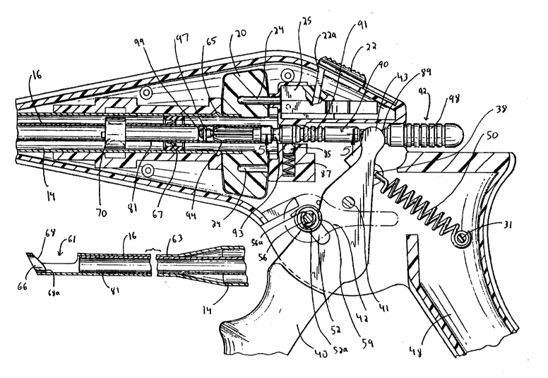
Referring now to the drawings and in particular
to Figs. 1 and lA, the surgical apparatus, designated
generally by reference numeral 10, is illustrated for
cutting body tissue. The apparatus has an elongated outer
tube or endoscopic portion 14 exten~;ng from housing or
handle assembly 12. Outer tube 14 is dimensioned and
configured for either insertion through a trocar cannula or
through a small incision in the body tissue. Slidably
positioned within outer tube 14 is an elongated hollow
inner cutting tube 16. Cutting tube 16 is advanced
distally upon actuation of handle assembly 12 to cut body
tissue positioned in window 61 of outer tube 14. An anvil
66, positioned at a distal end of the outer tube 14, forces
the severed body tissue portion rearwardly inside the
cutting tube 16. In this manner, the apparatus can be
inserted inside the body and the cutting tube 16 repeatedly
advanced to cut body tissue with the anvil 66 forcing the
cut tissue sections proximally inside the cutting tube to
enable storage of a plurality of tissue portions. The
cutting tube 16 can subsequently be easily separated from
the apparatus to access and remove the individual tissue
sections stored therein. This is achieved by removal of
the plug assembly, which includes a plug 92 and a plug
retainer 90, from the proximal end of cutting tube 16 in
the manner described below.
A release lever 42 is mounted on the handle
assembly 12 and cooperates with the trigger 40 to enable
movement of the trigger 40 to a release position so the
cutting tube 16 can be removed from the apparatus. The
release lever 42 is shown in Fig. 1 in the engaged
2173197
(blocking) position. Also shown in Figure 1 is rotation
knob 20 for rotating the outer tube 14 (and inner cutting
tube 16) about its longitll~in~l axis. A locking button 22
is engagable with the rotation knob 20 to lock the knob 20
and prevent rotation of the tubes 14, 16. The locking
button 22 and the release lever 42 are discussed in detail
below.
Turning now to the individual components of the
apparatus 10, and first to the handle assembly 12 as
illustrated in Figs. 1 and 3, handle assembly 12 is
composed of two housing halves 12a, 12b welded together or
attached by other known methods. Trigger 40 is pivotably
mounted to housing halves 12a, 12b via mounting pin 41
extending through opening 46. Trigger 40 is movable
between three positions. In the first (initial) position
shown in Fig. 4, the cutting tube 16 is in the retracted
position. In the second position as shown in Fig. 6,
trigger 40 is moved towards stationary grip 48 to advance
the cutting tube 16 distally. In the third position,
trigger 40 is moved to a distal release position shown in
Fig. 8 which enables the cutting tube 16 to be withdrawn
from the outer tube 14 in the manner described below.
In the initial position of trigger 40, spaced
apart projecting fingers 43 engage rod portion 89 of the
plug assembly, which is mounted to the cutting tube 16,
such that proximal (counterclockwise) movement of trigger
40 in the direction of the arrow of Fig. 6, slides cutting
tube 16 distally to cut the tissue positioned in window 61
(Fig. 6A).
Trigger 40 is normally biased to the third
position by extension spring 50; however it is prevented
from moving to this position by lever mounting shank 56
when release lever 42 is in the blocking position.
Therefore, when release lever 42 is in its normal blocking
position of Fig. 4, trigger 40 is essentially biased by
extension spring 50 to the first position. When release
lever 42 is pivoted to its release position of Fig. 8,
trigger 40 is no longer blocked and can spring forward to
21 73I97
its third position. As shown in Fig. 4, one end of
extension spring 50 is mounted on post 31 of stationary
grip 48 and the other end extends through aperture 38 in
trigger 40. Stop 45 limits the pivotal movement of trigger
40.
The release lever 42 blocks movement of trigger
40 due to mounting shank 56. Mounting shank 56 extends
through opening 33 in handle housing half 12a. Torsion
spring 59 biases lever 42 to the trigger blocking position
shown in Figs. 4 and 6. In this blocking position, trigger
is prevented from moving to its distal position by
mounting shank 56 because trigger notch 52 of trigger 40
abuts curved surface 56b of shank 56. This prevents the
removal of cutting tube 16 from outer tube 14 since
projecting fingers 43 remain engaged in rod portion 89 of
the plug assembly. When release lever 42 is pivoted to its
upward release position as shown in Fig. 8, trigger notch
52 can bypass mounting shank 56 due to the alignment of
flat 56a of mounting shank 56 with surface 52a of notch 52.
Consequently, trigger 40 springs forward to the release
position so that projecting fingers 43 are out of
engagement with the plug assembly to allow removal of the
cutting tube 16.
Turning now the outer tube 14 and with reference
to Figs. 1, 3 and 4, outer tube 14 has an open distal end
60 to mount anvil (tissue engaging member) 66, a window 61
to receive the body tissue to be cut, and a proximal end
portion 62 positioned within longitll~in~l recess 36 formed
by housing halves 12a, 12b. Lip 65 helps retain outer tube
14 in handle assembly 12. Central bore 64 of outer tube 16
is dimensioned to slidably receive cutting tube 16. A
cylindrically shaped seal 67 is positioned inside the outer
tube 14 and surrounds the cutting tube 16 to restrict the
egress of gas through the gap between the outer tube 14 and
cutting tube 16 if the body cavity is insufflated during
the procedure. Clearly, other types of seals to restrict
gas flow are also contemplated.
21 73I97
.
g
The outside diameter of the outer tube 14 is
preferably about 10 mm and preferably is tapered as shown
at portion 63 to an outside diameter of about 5 mm,
although other dimensions are clearly contemplated. Anvil
66 is mounted at distal end 60 of outer tube 14 via
dovetail fitting 66a (Fig. 4B) and has an angled surface 68
corresponding to the angled distal tip 75 of outer tube 12
(see Figs. 4A and 4B). The angled distal tip 75
facilitates manipulation and use of the apparatus as it can
more readily be hooked behind the target tissue. Angled
surface 68 of anvil 66 also has a straight portion 68a
which helps force the cut tissue sections proximally into
cutting tube 16 when the cutting tube 16 is advanced.
Angled surface 68 preferably forms an angle with respect to
the central longitudinal axis of outer tube 14 ranging from
approximately 90 degrees to about 140 degrees, and
preferably an angle R of 130 degrees. Alternatively,
other angles, such as a 90 angle can be utilized.
An orientation plate 70 is positioned within
outer tube 12 and extends through slots 72 to sit within
cavity 37 of handle assembly 12. D-shaped central opening
74 is dimensioned to receive cutting tube 16 therethrough.
Cutting tube 16, as shown in Figs. 3, 4, 4A and
4B has an open proximal end 80 and an open distal end 82.
The distal end 82 is shown having a circumferential
straight cutting edge, however alternately an angled edge
can be provided either integrally formed with the cutting
tube 16 or a separate element attached thereto. A
plurality of cutting teeth can also alternatively be
provided. The cutting tube 16 has an axial bore 86
extending the length thereof which forms a chamber for
storing the individual tissue portions as they are cut.
Anvil 66 forces the cut tissue sections rearwardly into
axial bore 86 to create space in the cutting tube 16 for
receiving the next cut tissue section when cutting tube 16
is once again advanced to cut tissue.
Cutting tube 16 has a flattened bottom surface 81
which sits on the flat bottom surface of D-shaped opening
21731~7
~ 74 of orientation plate 70. This prevents lateral movement
and rotation of the cutting tube as well as aligns the
cutting tube 16 inside outer tube 14.
Referring to Figs. 3, 4, 5 and SA, plug assembly
(end cap assembly) is mounted on the proximal end 80 of
cutting tube 16 and includes a plug 92 and a plug retainer
90 for preventing removal of plug 92. Plug retainer 90 is
seated in the proximal portion of axial bore 86, is spring
biased distally by compression spring 101 mounted on
tubular portion 117 of plug 92, and has a pair of spaced
apart ears 94 seated in a pair of notches 96 formed in the
cutting tube 16. Ears 94 are supported by shank 103 which
has an outer diameter almost equal to the inner diameter of
the cutting tube 16 to enable frictional engagement of
shank 103 and cutting tube 16 to stabilize the cutting tube
16. The proximal end of cutting tube 16 abuts surface 107
of cylindrical portion 113 of plug retainer 90. Proximal
extensions 116 are seated within recesses 118 formed in a
head portion 112 of plug 92.
Plug 92 has a knurled gripping surface 98 at its
proximal end and a cam nose 99 at its distal end. O-ring
97 is seated in a circumferential recess of cam nose 99 to
provide a seal to prevent the egress of insufflation gas
through the cutting tube 16 if the apparatus is used in a
procedure performed under insufflation. Other seals can
also be utilized. In the initial position, notches 111 of
ears 94 rest on camming surface 105 of camming nose 99 and
the ears 94 extend through notches 96 of cutting tube 16 to
connect the plug assembly to the cutting tube 16. This is
best shown in Fig. 4. If the plug 92 is gripped by its
knurled surface 98 and pulled proximally, cam nose 99 will
be pulled proximally between ears 94 to enable camming
surface 105 to cam the ears 94 further outwardly into
locking engagement with notches 96 of cutting tube 16 as
shown in Fig. 8 and 9. This enables the cutting tube 16 to
be removed. Note that this locking engagement prevents
removal of plug 92 from cutting tube 16 if knurled surface
98 is pulled. Thus, the ears also function to provide a
-_ 2173197
11
locking device to prevent inadvertent disengagement of the
plug assembly from the cutting tube 16.
The plug assembly can be removed from cutting
tube 16 to access the tissue stored therein only when
knurled gripping surface 91 of the plug retainer 90 can be
grasped. This occurs only when the release lever 42 has
been rotated to its release position to disengage the
projecting fingers 43 of trigger 40 from rod portion 89,
and the cutting tube 16 is withdrawn from the outer tube 14
as shown in Fig. 10. Only when this occurs can knurled
surface 91 be accessed. When plug retainer 90 is pulled
proximally in the direction of the arrow, the ears 94 can
slide out of notches 96 as camming release surfaces 108 are
forced inwardly by the wall 115 of cutting tube 16 adjacent
the notches 96 and plug retainer 90 (and attached plug 92)
can be removed from the outer tube 14 as shown in Fig. 11.
The tissue sections T can then be removed and organized for
pathology.
As best shown in Fig. 7, recess 93 in the plug
assembly is configured to receive detent sphere 85 when the
trigger 40 is in the release position. Sphere 85 is seated
within recess 83 in housing half 12b and is spring biased
by compression spring 87 to snap into engagement with
recess 93 in plug retainer 90 to prevent the cutting tube
16 from slipping out of outer tube 14 when the trigger 40
is in the release position (see Fig 7A). This engagement
also provides a tactile feel to the user that the cutting
tube 16 is released for withdrawal from outer tube 14 as
well as when the cutting tube 16 has been properly re-
inserted into the outer tube 14 of the apparatus.
Turning now to the rotation knob 40 and withreference to Figs. 1 and 3, as mentioned above, rotation
knob 20 extends through cutout 34 in housing halves 12a,
12b and is mounted to outer tube 14 to rotate outer tube 14
about its longitll~inAl axis. Rotation of outer tube 14
causes rotation of cutting tube 16 due to orientation plate
70 which rotates with outer tube 14. Leg 22a of rotation
locking button 22 is seated within recess 23 of mounting
2173197
12
block 25, slidably mounted on handle assembly 12, and
spring biased to the locking position by spring 30.
Locking button 22 is shown in Figs. 1 and lA in the locking
position. In this locking position, the pair of locking
fingers 24 of mounting block 25 engage a pair of reces-~es
26 in rotation knob 20 to thereby prevent rotation of knob
20. When it is desired to rotate outer tube 14 to change
the orientation of the window 61, locking button 22 is slid
proximally in the direction of the arrows of Figs. 2 and
2A. This slides mounting block 25 proximally to release
the locking fingers 24 from recesses 26 and allow free
rotation of rotation knob 20. When locking button 22 is
released by the user, it springs back into the locking
position under the biasing force of spring 30.
An alternate embodiment of a rotation knob
locking mechanism is shown in Fig. 3A. Locking button 122
has a mounting leg 123 seated within recess 126 in locking
plate 124. Locking plate 124 has a single integral
extension 125 which engages a single recess in the rotation
knob to prevent rotation.
In operation, with reference initially to Figs.
4, 4A and 4B, trigger 40 is initially spaced from
stationary grip 48 with projecting fingers 43 engaging rod
portion 89 of plug 92. As shown, cutting tube 16 is in the
proximal (retracted) position and release lever 42 is in
the blocking position parallel to the longitudinal axis of
the tubes 14, 16.
The apparatus is inserted into the body, either
through a cannula or directly through a small incision, and
the outer tube 14 is placed adjacent the surgical site such
that the tissue to be severed is seated within window 61.
If the user needs to re-orient the window 61, locking
button 22 is slid proximally to disengage locking fingers
24 from the recesses 26 in the rotation knob 20. Locking
button 22 is held by the user in this proximal position and
the rotation knob is turned to rotate outer tube 14 (and
window 61) to the desired position. Once the tissue is
properly seated, trigger 40 is actuated by squeezing it
2173197
13
towards stationary grip 48 to advance cutting tube 16
distally towards anvil 66 as shown in Figs. 6, 6A and 6B.
The cutting edge of the cutting tube 16 passes through the
window 61 to pierce and ~issect the body tissue seated
therein. As the cutting tube 16 passes over anvil 66,
angled surface 68 and straight surface 68a enter the hollow
interior of the cutting tube 16, and force the dissected
tissue proximally into the cutting tube 16. After
dissection, trigger 40 is released, returning cutting tube
16 to the proximal position of Fig. 4A. Note that plug 92
cannot be removed from the cutting tube 16 due to the
engagement of ears 94 with the notches 96 of cutting tube
16.
The user can then once again squeeze trigger 40
to advance cutting tube 16 to dissect another portion of
the body tissue positioned in window 61. As the cutting
tube 16 advances to its distalmost position, anvil 66 once
again forces the dissected tissue rearwardly (proximally)
into cutting tube 16. The cutting tube 16 can be
repeatedly advanced and retracted in this manner to ~ ct
the entire desired portion of body tissue, with the anvil
66 advantageously forcing the body tissue sections
proximally to provide room for the next body tissue
portion. Fig. 9 illustrates a plurality of body tissue
sections T positioned within cutting tube 16.
Note that when trigger 40 and cutting tube 16 are
in the position of Figs 4 and 4A, the cutting tube 16
cannot be removed from outer tube 14. If the user grasps
gripping surface 98 of plug 92 in an attempt to remove
cutting tube 16, projecting fingers 43 of trigger 40 will
block removal of the cutting tube 16. Also in the position
of Figs. 4 and 4A, the plug 92 cannot be removed from the
cutting tube 16 because ears 94 engage notches 96 of
cutting tube 16 and if the user pulls on gripping surface
98, the camming nose 99 of plug 92 will cam the ears
further into engagement with notches 96.
After use, to remove the tissue from the chamber
86 of cutting tube 16, release lever 42 is rotated
2173I97
-
14
counterclockwise to the position of Fig. 8 so that flat 56a
of mounting shank 56 is in alignment with surface 52a of
trigger notch 52. Consequently, notch 52 rides over
mounting shank 56 to allow trigger 40 to spring forward to
its distal release position under the force of extension
spring 50. In this distal release position, the projecting
fingers 43 are disengaged from notch 89 in the plug 92.
Thus, when the user grasps gripping surface 98 of plug 92
and pulls proximally, the entire cutting tube 16 is
withdrawn from the outer tube 14 through the opening in
proximal end 62 as the ears 94 of plug retainer 92 engage
notches 96 in cutting tube 16.
After the cutting tube 16 has been removed as
shown in Fig. 9, to access the tissue portions, gripping
surface 91 of plug retainer 90 is grasped and pulled
proximally (Fig. 10). This removes the plug 92 and plug
retainer 90 from cutting tube 16 since the ears 94 are
cammed closed by wall 115 adjacent notches 96 so they can
slide out of notches 96. Fig. 11 illustrates the plug
assembly separated from the cutting tube 16. The tissue
sections T can then be removed from cutting tube 16 and
arranged in a manner similar to their configuration prior
to dissection to assist in examination and testing of the
tissue. Figs. 12 and 13 illustrate one method of removing
the tissue sections T in which plunger 100 is inserted
through the open proximal end 80 of cutting tube 16 to
force the tissue sections out of the open distal end 82.
For subsequent use of the instrument, cutting
tube 16 is inserted through the opening in proximal end 62
of outer tube 14 until the user feels the engagement of
detent sphere 85 with recess 93 as in Fig. 7A. Trigger 40
is then squeezed towards stationary grip 48, causing
release lever 42 to rotate clockwise over center, under the
force of torsion spring 59, to its original position of
Fig. 4 enabling projecting fingers 43 to engage rod portion
89 of plug 92. The cutting tube 16 can then be actuated by
squeezing trigger 40 in the manner described below for
reuse.
2173197
The apparatus can be entirely disposable and can
be discarded after use. It can also be partially
disposable with some parts discarded e.g. the cutting tube
and plug assembly, and the remaining parts, e.g. the handle
assembly, reused. Alternatively, the apparatus can be
composed of suitable materials to enable re-sterilization
of the instrument parts for subsequent reassembly and
reuse. The apparatus 10 can be packaged in a kit with
several cutting tubes (and plug assemblies).
The instrument 10 can be used to dissect tissue
in a variety of surgical procedures. For example, in
endoscopic discectomy procedures, the instrument can be
inserted into the disc space to quickly dissect portions of
the disc. The cutting tube can then be removed in the
manner described above and the tissue sections removed and
analyzed. The instrument can also be used as a ronguer for
cutting and storing sections of bones in other surgical
procedures.
It will be understood that various modifications
may be made to the embodiments disclosed therein. For
example, a cutting tube having teeth or having other
cutting configurations such as a beveled edge can be
utilized. Moreover, the instrument can be either
disposable or reusable. Therefore, the above described
should not be construed as limiting, but merely as
exemplifications of preferred embodiments. Those skilled
in the art will envision other modifications within the
scope and spirit of the claims appended hereto.