Language selection

Search

Patent 2173198 Summary

Third-party information liability

Some of the information on this Web page has been provided by external sources. The Government of Canada is not responsible for the accuracy, reliability or currency of the information supplied by external sources. Users wishing to rely upon this information should consult directly with the source of the information. Content provided by external sources is not subject to official languages, privacy and accessibility requirements.

Claims and Abstract availability

Any discrepancies in the text and image of the Claims and Abstract are due to differing posting times. Text of the Claims and Abstract are posted:

  • At the time the application is open to public inspection;
  • At the time of issue of the patent (grant).
(12) Patent: (11) CA 2173198
(54) English Title: INDICATOR LIGHT FOR AN APPLIANCE
(54) French Title: VOYANT POUR ELECTROMENAGER
Status: Deemed expired
Bibliographic Data
(51) International Patent Classification (IPC):
  • F24C 15/00 (2006.01)
  • F24C 3/12 (2006.01)
  • F24C 5/16 (2006.01)
  • F24C 7/08 (2006.01)
(72) Inventors :
  • BALES, MICHAEL (United States of America)
  • PICKERING, MARK A. (United States of America)
(73) Owners :
  • MAYTAG CORPORATION (United States of America)
(71) Applicants :
  • MAYTAG CORPORATION (United States of America)
(74) Agent: FINLAYSON & SINGLEHURST
(74) Associate agent:
(45) Issued: 2004-04-27
(22) Filed Date: 1996-04-01
(41) Open to Public Inspection: 1997-02-26
Examination requested: 1999-06-14
Availability of licence: N/A
(25) Language of filing: English

Patent Cooperation Treaty (PCT): No

(30) Application Priority Data:
Application No. Country/Territory Date
08/519,199 United States of America 1995-08-25

Abstracts

English Abstract

An indicator for an appliance includes a light bar formed of molded plastic material. The bar is interconnected to the control elements of the appliance so the periphery of the bar lights whenever any element of the appliance is active. The bar is designed so the periphery of the light bar is exposed along the exterior edge of the appliance.


French Abstract

Un voyant pour appareil électroménager comprend une barre lumineuse conçue en matière plastique moulée. La barre est interconnectée aux éléments de commande de l'appareil électroménager de manière que le contour de la barre s'allume dès qu'un élément de l'appareil est activé. La barre est conçue de manière que le contour de la barre lumineuse soit exposé le long du bord extérieur de l'appareil.

Claims

Note: Claims are shown in the official language in which they were submitted.


The embodiments of the invention in which an
exclusive property or privilege is claimed are defined
as follows:

1. A cooking element activation indicator for a
cooking appliance comprising:
a control housing mounted to a cooking appliance;
an indicator light bar having a peripheral edge
extending in more than one plane and mounted to
the control housing;
a plurality of cooking elements mounted to the cooking
appliance and operatively connected to user
activated controls, the controls mounted in the
control housing;
a light source within said indicator light bar;
an electrical circuit for activating said light source
to emit light whenever a cooking element of the
cooking appliance is activated by the user
activated controls, light from said light source
illuminating the edge of said indicator light bar
and indicating that a cooking element is
activated.

2. The activation indicator of claim 1 and wherein
the indicator light bar being integrally mounted to the
control housing.

5


3. An appliance activation indicator comprising:
a plurality of cooking elements mounted in a cooking
appliance;
a control housing mounted in the appliance and having a
peripheral edge;
a control for controlling the cooking elements, the
control mounted in the control housing;
an indicator light bar having a periphery edge
extending in more than one plane and being
electrically connected to the control for
selective activation or deactivation coinciding
with activation and deactivation of the cooking
elements, the indicator light bar being mounted in
the control housing;
a light source for emitting light within the indicator
light bar;
the light emitted from the light source being directed
to the periphery edge of the indicator light bar;
the indicator light bar being mounted to the cooking
appliance so that the periphery edge of the
indicator light bar is visible;
the periphery edge of the indicator light bar
conforming to the peripheral edge of the control
housing;
the control activating the light source upon activation
of any of the cooking elements.


6

Description

Note: Descriptions are shown in the official language in which they were submitted.


2~~31~$
INDICATOR LIGHT FOR AN APPLIANCE
BACKGROUND OF THE INVENTION
The present invention relates to an indicator
light for an appliance. The indicator light is
particularly useful for a cooking appliance, but can
also be used for other home appliances such as
dishwashers, washers, dryers and microwave ovens.
It is common in the industry to provide an
indicator light on cooking appliances that is
illuminated during operation of any of the cooking
elements. This is done, for example, by placing a
light source such as a light emitting diode on the
front or top of the appliance. This light source is
then interconnected to each of the control elements so
that activation of any of the surface cooking elements
also activates this light. Another approach is that of
backlighting the control knobs so an indication is
provided as to which of the elements is active.
Placing an indicator light on the front of the
appliance is not considered to provide an aesthetically
pleasing design. Additionally, a light placed in the
front or top of the appliance cannot always be seen
from all angles. This is frequently important because
a consumer may move about the kitchen. Additionally,
it is common for more than one person to be in the
kitchen. It is therefore important to have an
indicator that is generally visible throughout the
kitchen. While the backlighting of the control knobs
provides a more aesthetically pleasing indication, it
suffers from the inability to be seen from all angles.
These approaches, while adequate, do not provide a
complete solution to the need.
1

CA 02173198 1999-08-06
Therefore, it is an aspect of the present invention to
provide an indicator light for an appliance that is easily
visible from many angles.
A further aspect of the invention is to provide an
indicator light for an appliance that is aesthetically
pleasing.
sU~SARY of THE INVENTION
The foregoing aspects are achieved by an indicator
light for an appliance comprising a light bar that conforms to
the contour of the appliance. The light bar is made from a
plastic material, the outer periphery of which is exposed
around the control panel of the appliance and which emits
light when any element of the appliance is active.
More particularly the invention in one broad aspect
provides a cooking element activation indicator for a cooking
appliance comprising a control housing mounted to a cooking
appliance and an indicator light bar having a peripheral edge
extending in more than one plane and mounted to the control
housing. A plurality of cooking elements are mounted to the
cooking appliance and operatively connected to user activated
controls, the controls mounted in the control housing. There
is a light source within the indicator light bar and an
electrical circuit is provided for activating the light source
to emit light whenever a cooking element of the cooking
appliance is activated by the user activated controls, light
from the light source illuminating the edge of the indicator
light bar and indicating that a cooking element is activated.
BRIEF DESCRIPTION OF THE DRAPiINC~S
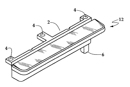
Figure 1 is an isometric view of a light bar assembly.
Figure 2 is side view of the light bar assembly.
Figure 3 is a bottom view of the appliance control
housing.
2

CA 02173198 1999-08-06
Figure 4 is a plan view of a cooktop incorporating a
light bar.
Figure 5 is a logic circuit diagram of the connections to
the light bar.
DETAILED DESCRIPTION OF T8E PREFERRED EN80DI1~SNT
Referring to Figures 1 - 4, a cooktop 50 is shown, including
cooking elements 52 and control elements 56,58,60,62 included in a
control housing 54. A light bar 10 is included in the control
housing 54 and will be described in detail below. The light bar 10
is mounted into the control housing 54 so that the lighted
periphery 12 of the light bar 10 extends around the
2A


front edge of the control housing 54. The light bar
10, shown in Figures 1 and 2, is formed of molded
plastic. Incandescent lamps 13 are housed in the light
bar 10. The light is directed to the periphery 12 of
the light bar 10 via a reflecting bar 11 within the
light bar 10. When the incandescent lamps 13 are
illuminated the light from the lamps is directed
towards the top of the light bar 10. The top of the
light bar 10 includes a reflecting bar 11. The
reflecting bar 11 is formed to reflect light impinging
upon it towards the periphery 12 of the light bar 10.
Thus, light from the lamps 13 is redirected upon
hitting the reflecting bar 11 to illuminate the
periphery 12 of the light bar 10.
The molded plastic may be colored to accentuate
the light. For example, in the present design the
light is used as an indication of activation of a
cooking element; the plastic is appropriately red. When
the lamps 13 are activated the periphery 12 of the
light bar 10 is illuminated and appears as a line of
red light. This reddish color is generally recognized
by users as an activation indication.
The light bar 10 further includes fastener tabs 4,
for fastening the light bar 10 to the control housing
54. An electrical connecter 6 is provided on the
bottom of the light bar 10 to provide power to the
lamps 13. The control housing 54 includes locations 22
for each of the control elements 56,58,60,62. An
electrical interconnection is provided so that upon
activation of any of the heating surface control
elements 56,58,60,62 electrical power is provided to
activate the lamps 13 in the light bar 10. This can be
done either via a hard-wired electrical circuit
connection or under the control of a microprocessor
control if available. As shown in Figure 5, if any of
3

CA 02173198 1999-08-06
several control elements is activated, power is
interconnected to the lamps 13. These signals are connected in
a logical "OR~~ so activation of any element illuminates the
light bar 10. The light bar is attached to the control housing
54 via screws or other fasteners (not shown) through the
fastener tabs 4.
The control housing 54 is mounted to a cooktop 50. The
outer periphery 12 of the light bar 10 is exposed along the
front of the cooktop 50. A facia 70 is attached to the top of
the control housing 54, covering all but the outer periphery
of the light bar 10. In this way, the light 10 becomes
integral to the control housing 54.
Upon activation of any of the control elements
56,58,60,62 power is supplied to the lamps 13 of the light bar
as described previously. The outer periphery 12 is then
illuminated, giving an aesthetically pleasing indication of
activation. Because the light bar periphery 12 extends around
the front and sides of the control housing 54, the indication
light is visible from either side and the front of the
cooktop. Thus, the outer periphery 12 of the light bar 10
extends in more than one plane. This allows a user to
identify activation of a heating element from a wide range of
angles and distances from the appliance.
In the drawings and specification there has been set
forth a preferred embodiment of the invention, and although
specific terms are employed, these are used in a generic and
descriptive sense only and not for purposes of limitation.
Changes in the form and the proportion of parts as well as in
the substitution of equivalents are contemplated as
circumstances may suggest or render expedient without
departing from the spirit or scope of the invention as further
defined in the following claims.
4

Representative Drawing
A single figure which represents the drawing illustrating the invention.
Administrative Status

For a clearer understanding of the status of the application/patent presented on this page, the site Disclaimer , as well as the definitions for Patent , Administrative Status , Maintenance Fee  and Payment History  should be consulted.

Administrative Status

Title Date
Forecasted Issue Date 2004-04-27
(22) Filed 1996-04-01
(41) Open to Public Inspection 1997-02-26
Examination Requested 1999-06-14
(45) Issued 2004-04-27
Deemed Expired 2014-04-02

Abandonment History

There is no abandonment history.

Payment History

Fee Type Anniversary Year Due Date Amount Paid Paid Date
Application Fee $0.00 1996-04-01
Registration of a document - section 124 $0.00 1996-06-27
Maintenance Fee - Application - New Act 2 1998-04-01 $100.00 1998-03-31
Maintenance Fee - Application - New Act 3 1999-04-01 $100.00 1999-02-03
Request for Examination $400.00 1999-06-14
Maintenance Fee - Application - New Act 4 2000-04-03 $100.00 1999-12-15
Maintenance Fee - Application - New Act 5 2001-04-02 $150.00 2000-12-06
Maintenance Fee - Application - New Act 6 2002-04-01 $150.00 2001-12-13
Maintenance Fee - Application - New Act 7 2003-04-01 $150.00 2002-12-11
Maintenance Fee - Application - New Act 8 2004-04-01 $150.00 2003-11-19
Final Fee $300.00 2004-02-02
Maintenance Fee - Patent - New Act 9 2005-04-01 $200.00 2004-11-19
Maintenance Fee - Patent - New Act 10 2006-04-03 $250.00 2005-12-06
Maintenance Fee - Patent - New Act 11 2007-04-02 $250.00 2007-03-19
Maintenance Fee - Patent - New Act 12 2008-04-01 $250.00 2008-03-17
Maintenance Fee - Patent - New Act 13 2009-04-01 $250.00 2009-03-18
Maintenance Fee - Patent - New Act 14 2010-04-01 $250.00 2010-03-23
Maintenance Fee - Patent - New Act 15 2011-04-01 $450.00 2011-03-09
Maintenance Fee - Patent - New Act 16 2012-04-02 $450.00 2012-03-14
Owners on Record

Note: Records showing the ownership history in alphabetical order.

Current Owners on Record
MAYTAG CORPORATION
Past Owners on Record
BALES, MICHAEL
PICKERING, MARK A.
Past Owners that do not appear in the "Owners on Record" listing will appear in other documentation within the application.
Documents

To view selected files, please enter reCAPTCHA code :


To view images, click a link in the Document Description column. To download the documents, select one or more checkboxes in the first column and then click the "Download Selected in PDF format (Zip Archive)" or the "Download Selected as Single PDF" button.

List of published and non-published patent-specific documents on the CPD .

If you have any difficulty accessing content, you can call the Client Service Centre at 1-866-997-1936 or send them an e-mail at CIPO Client Service Centre.


Document
Description 
Date
(yyyy-mm-dd) 
Number of pages   Size of Image (KB) 
Abstract 1996-07-10 1 11
Representative Drawing 1998-03-27 1 38
Representative Drawing 2002-09-26 1 10
Description 1996-07-10 4 164
Claims 1996-07-10 2 42
Drawings 1996-07-10 2 62
Cover Page 1996-07-10 1 16
Description 1999-08-06 5 201
Claims 1999-08-06 2 61
Drawings 1999-08-06 2 69
Cover Page 2004-03-25 1 34
Correspondence 2004-02-02 1 30
Assignment 1996-04-01 7 242
Prosecution-Amendment 1999-06-14 1 30
Prosecution-Amendment 1999-08-06 9 301