Note: Descriptions are shown in the official language in which they were submitted.
WO95/15258 2 17 3 3 ~ 4 PCT~S94/02346
DIAMOND COATED TOOLS AND PROCESS FOR MAKING
Technical Field
The present invention relates to a tool
having a strongly adherent diamond coating deposited
thereupon and to a process for making this product. It
is especially concerned with diamond coated cutting
tools for chip forming ma~-h;n;ng and a process for
making them.
B~C1~G~
In recent years, chemical vapor deposition
(CVD) diamond coatings have been applied to a variety
of substrate-material cutting tools intended for the
same applications as single point, brazed-on
pol~y~Lalline diamond (PCD) tipped tools (see
"Advanced Cutting Tool Materials," K~nn~metal Inc.
(1988), Pages 1, 2, 77-86, 94-98, 101 and 102). While
CVD diamond coated tools provide the machin;st with
multiple cutting edges on inserts with or without
chipbreaker structures, their inconsistent machining
results, due to poor coating adhesion, has resulted in
a failure of the CVD diamond coated tools to be
competitive with PCD tools in most commercial
applications.
~arious approaches have been made to the
formation of diamond coating layers on various surfaces
by CVD methods (e.g., hot filament, DC plasma jet and
microwave plasma) in which gases such as methane (CH4)
are thermally decomposed. However, ~i~ond coating
layers formed by low pressure vapor-phase synthesis
methods generally have a low adhesive bond strength to
W095/~5~8 PCT~S94/02346
~1733~4
^ -2-
the substrate. Accordingly, what is desired is a
coated substrate in which the adherence of the coating
to the substrate is sufficient to retain the coating on
the substrate for the time that it takes for the
coating to gradually wear out by abrasion during
mach;n; ng of a workpiece material. Early or premature
flaking of the coating prior to the wearing out of the
coating causes unpredictable and inconsistent tool
lifetimes, which is unacceptable to most users of PCD
tipped tools. In addition, the diamond coating
thiCk~CC should be thick enough so that each cutting
edge provides at least forty percent of the wear life
of PCD tools in order to be competitive with those
tools.
One approach to this problem is disclosed in
U.S. Patent No. 5,068,148, which issued on
November 26, 1991. The '148 reference discloses a
method for producing a diamond coated tool member
wherein a cemented carbide substrate is chemically
etched to remove cobalt existing in the outermost
portion of the substrate. Such etch; ng steps may
generate internal interconnecting porosity which
dimi n; cheS the toughness and wear resistance of the
cutting tool insert, but absent chemical e~c-h;ng, tool
performance may dimi ni ch due to coating delamination
caused by poor preparation of the substrate surface
(e.g., too much cobalt left on the surface). The '148
reference calls for heat-treating a ground substrate at
a temperature between 1000C-1600C for 30 to 90
minutes in a vacuum or in a non-oxidizing atmosphere
before chemical et~h;~. If the heat treating
temperature ~c~ 1600C, the hard grains of the
substrate become bulky, and the surface of the
substrate becomes extraordinarily rough, so that the
substrate cannot be used for manufacturing a tool
member.
~ W095/15258 217 3 3 5 ~ PCT~S94/02346
In another approach, disclosed in European
Patent Application No. 0 518 587, the surfaces of a
cemented tungsten carbide substrate are also etched for
the purpose of improving diamond coating adherence.
It is the inventors' belief, after
examination of diamond coated cemented carbide tools
presently ~eing commercially marketed, that where an
etch; ng step is used to improve diamond adhesion (to 60
to 100 kg in the Rockwell A indentation adhesion test),
etchi~g has preferentially removed significant amounts
of cobalt from the surface and from just beneath the
surface. This results in interconnected porosity just
h~ne~th the substrate surface, creating a weakened
structure which undermines the ability of the diamond
coating to remain attached to the tool during mach;n;~g
operations, and which results in flaking of the
coating, especially during interrupted mach; n; ~g
operations.
U.S. Patent No. 5,204,167, which issued on
April 20, 1993, discloses a diamond coated sintered
body in which the average size of recrystallized
tungsten carbide in the surface layer is finer as
compared with that existing in the inner portions of
the substrate. The '167 reference teaches that
increased adhesion between the diamond film and the
substrate is because graphite generated at an initial
stage of diamond deposition is used for recarburization
of a surface decarburized layer of the substrate, so
that graphite formed at the interface between the
surface layer and the film is decreased.
Such approaches leave unsolved the challenge
of providing a high bond strength between the coating
and the substrate.
Current practice in the design of
conventional, PCD cutting tools calls for the tool to
have a sharp cutting edge for both turning and milling
applications on non-ferrous and non-metallic
Wos5/1s258 ` ~ ~ ; PcT~S94102346 ~
2 17 3 3 ~ ~ -4-
workpieces. The use of sharp edges provides lower
cutting tool forces during ma~h;ning and workpiece
surface fin; ~h~C having the required characteristics,
e.g., low surface roughnecs.
Diamond coated cutting tool inserts should
ideally provide the same workpiece surface
characteristics to be commercially competitive with
conventional PCD tools. Another one of the factors
currently limiting the acceptance of diamond coated
tools has been the difficulty of providing acceptable
workpiece surface f~n;~hec, especially in fin; ch; n~
operations. Conventional PCD tools often contain a
metallic binder, such as cobalt, which holds the
diamond particles together. When properly ground, the
PCD provides a substantially smooth cutting surface and
imparts a substantially smooth surface to the
workpiece. In contrast, diamond coatings do not
contain a binder phase. They typically have a rough,
- faceted surface on a microscopic scale. Such
microscopic ro1l~hn~cs leads to rough workpiece f;n;~h~c
in cutting operations. Under prior approaches, the
purer (or more perfect) the diamond coating, i.e., more
sp3 and less sp2 (graphitic) bonded component, the more
highly faceted the coating becomes. Such coatings can
be made smoother by increasing the amount of graphitic
component, but wear resistance, and tool lifetime,
decrease as a result. Although chemical polishing with
reactive materials and co~ounds or me~h~nical
polishing with diamond grit may be used to produce a
smooth diamond surface, the road r~;n~ open for
improved approaches.
Accordingly, it would be desirable to provide
a high purity ~;~cn~ coating on a cutting tool
substrate that will be highly adherent in use, and will
preferably achieve workpiece surface finishes
comparable to those provided by conventional PCD tools.
-
WO95/15258 217 33 5 ~ PCT~S94/02346
.,
-5-
Until the present invention, there remained
an unsolved need for simple, yet effective techniques
for consistently providing a highly adherent diamond
coating and for providing a smooth surface of a high
purity, highly faceted diamond coating on a three-
dimensional shape, e.g., a cutting tool insert.
~UMNARY OF ~HB lNv~ ON
The product according to the present
invention is directed to a diamond coated tool,
preferably a cutting tool for chip forming machi n ing of
materials.
The tool has a cermet substrate, to which a
diamond coating is adherently bonded. The cermet
substrate has hard grains bonded together by a metallic
binder. At the substrate surface, there are hard
grains that are large. These large, hard grains
provide the substrate with an irregular surface. The
diamond coating has a strong adhesion to the irregular
substrate surface. Where the tool is a cutting tool
for chip forming machining of a material, the substrate
has a flank surface and a rake surface and a cutting
edge formed at the juncture of the rake and flank
surfaces. The diamond coating is adherently bonded to
each of these surfaces. The substrat~, in accordance
with the present invention, is also preferably
characterized by an absence of interconnected porosity
in the substrate regions adjacent to the irregular
substrate surfaces to which the diamond coating is
bonded.
In a preferred embodiment of the present
product, the cermet substrate is a tungsten carbide
h~5~ (i.eO, > 50 w/o WC) cemented carbide and said
hard grains include tungsten carbide grains.
Preferably, the metallic binder forms about
0.2 to 20 w/o of the tungsten carbide based cemented
carbide and the metallic binder is selected from the
W O 95/lS2S8 2 ~ 7 3 3 ~ 4~ PC~rrUS94/02346
.~ . . ~ . ".
--6--
-
group of cobalt, cobalt alloys, iron, iron alloys,
nickel and nickel alloys.
In a more preferred embodiment, the metallic
binder is cobalt, or a cobalt alloy, and cobalt forms
about 0.5 to about 7 weight percent, and most
preferably, about 1.0 to abou~ 7 weight percent of the
Lu~y~- Ien carbide based cemented carbide.
Preferably, the average adhesion strength of
the diamond coating to the substrate surface is at
least 45 kg, and more preferably, at least 60 kg, and
most preferably, at least 80 kg in Rockwell A
indentation tests.
The diamond coating on the rake face of
cutting tools preferably has an average thickness of
about 5 to about lOO~m, with about 22 to about 50 being
preferable for tools to be used in continuous and
interrupted finish turning of aluminum alloys such as
A380 and A390 to obtain acceptable tool lives at a
reasonable manufacturing cost.
In a preferred option, especially for finish
marhi n; ng applications, the diamond coating adherently
bonded to the rake face is substantially left in its
as-deposited rough surface condition, preferably,
having a surface ro~ghn~cs, Ra~ of greater than
35 micro;nchPs, while the diamond coating adherently
bonded to the flank surface is made smoother.
The product according to the present
invention is preferably made by a process, also in
accordance with the present invention, which comprises
the steps of:
1. Sintering a cermet substrate for a time,
at a temperature and in an atmosphere to produce grain
growth on the substrate surfaces sufficient to provide
the substrate rake surface with a surface roughness,
Ra~ of greater than 25 microinches, while reducing the
roncentration of metallic binder on that surface.
Preferably, the surface roughness, Ra~ produced in the
WO95115258 ~17 33 5 4 PCT~S94/02346
--7--
sintering step, is greater than 30 micro;nr~Pc, and
more preferably, at least 40 microi ~Ch~C. The
atmosphere used, preferably, is nitrogen, at a partial
pressure of about 0.3 to about 50 torr, preferably,
about 0.3 to 5 torr, more preferably, about 0.3 to 2.0
torr, and most preferably, about 0.3 to 0.7 torr.
2. These surfaces are then diamond coated
by adherently depositing, by vapor deposition, a
diamond coating thereon. Preferably, the substrate
temperature during the diamond deposition process is
between 700C and 875C, and is more preferably, about
750C to about 850C.
This process is controlled to produce an
average adhesion strength between the diamond coating
and the substrate of greater than 45 kg, preferably, at
least 60 kg, and more preferably, at least 80 kg, as
determined by the Rockwell A indentation t~hn ique.
Preferably, following the sintering step, the
surfaces of the substrate to be coated are scratched
with diamond to create diamond nucleation sites in
preparation for diamond coating.
In another preferred embodiment of the
present invention, the step of smoothing the surface
roughness of the diamond on the flank face of the tool
is perfor~ed, preferably, by buffing the flank face.
In still a further preferred ~ho~; ment of
the present invention, the cermet substrate prior to
the sintering step described above is at least
~ubstantially fully densified (i.e., has been
previously sintered~ and has a surface which is in a
ground condition.
These and other aspects of the present
invention will become more apparent upon review of the
detailed description of the invention in conjunction
with the drawings, which are briefly described below.
, 2 ~ 7 3 3 ~ ~ PCT/US94/02346
--8--
,R~T~F D~CRIPTION OF THE DRAWING8
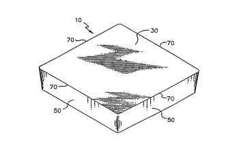
FIGURE LA shows an embodiment of a cutting
tool substrate in accordance with the present
invention.
FIGURE lB shows a partial cross section
through the cutting tool substrate of Figure lA
perpendicular to a cutting edge after it has been
coated in accordance with the present invention.
FIGURES 2-ll are Cc~n~i~g electron microscopy
(SEM) photomi~.uyLaphs which depict secondary electron
images (SEI) of a cutting tool at various stages in a
preferred embodiment of the process and product of the
present invention. (All figures are at 2000x
magnification, except for Figure 10, which is at
1000x.)
FIGURE 12 illustrates an optional buffing
step using a rotating brush impregnated with diamond
grit.
n~TAI~ED DB8CRIPTION OF TR~ l~.v~ ON
In accordance with the present invention,
Figure lA shows a preferred embodiment of an in~Ahle
cutting tool substrate to be coated with diamond in
accordance with the present invention. The tool
substrate has a rake surface 30 and flank surface 50.
At the juncture of the rake surface 30 and the flank
surface 50 is a cutting edge 70. The cutting edge 70
may be in either a sharp, honed, chamfered, or
chamfered and hon~ condition, dep~;ng on application
requirements. The hone may be any of the styles or
cizes of hones used in the cutting tool industry.
Preferably, the cutting edge has a radius hone,
preferably, of about .0005 to .0015 inch. The cutting
tool substrate may also be made in any of the st~n~rd
shapes and sizes (for example, SNGN-422 and TPGN-322
(see ANSI B212.4-1986)). Inserts may also have various
chipbreaker structures (not shown) on their rake face
as well to facilitate breakage and removal of chips.
~ W095/lS258 217 3 35 4 PCT~S94/02346
_9_
Where chipbreaker structures are to be coated, some or
all of these structures may be in an as-molded
condition (i.e., ullyrOulld).
In accordance with the present invention,
Figure lB shows a partial cross section through the
coated cutting tool 80 which is composed of the cermet
substrate 10, shown in Figure lA, with a diamond
coating 90 adherently bonded to its rake surface 30,
flank surfaces 50 and cutting edges 70. The bottom
surface of the substrate 10 may or may not be coated
with diamond.
The substrate used in the present invention
is a cermet having hard grains and a metallic binder
holding said hard grains together. The cermet
composition may be any of those used in the prior art
for cutting tool applications and include titanium
carbonitride based and ~u~y~Len carbide based
compositions. The metallic binder utilized in these
compositions include cobalt, cobalt alloys, nickel,
nickel alloys, iron and iron alloys.
Preferably, a Lu~lyxLen carbide based (>50 w/o
WC) cemented carbide is utilized for the substrate.
Such a composition should have about 0.5 to about
20 w/o, preferably, 1.0 to 7 w/o, metallic binder of
cobalt or a cobalt alloy. Such a composition would
contain hard ~lly~en carbide grains and may also
contain other hard grains, including carbides, nitrides
and carbonitrides of other elements, solid solution
carbides and solid solution carbonitrides of tungsten
and other elements. Such elements may include Ti, Hf,
Zr, Ta, Nb, V, Mo and Cr. In a preferred embodiment,
the presence of Ti, Hf, Zr, Ta, Nb, V, Mo and Cr is
limited to less than 1 w/o, and more preferably, less
than 0.6 w/o total, such that the c~nted carbide
substrate consists essentially of tungsten carbide and
cobalt or a cobalt alloy (such as a Co-W alloy).
WO95/15258 PCT~S94/02346 ~
21733~4
--10--
For example, applicants have found that the
present invention provides particularly good adhesion
results when two tungsten carbide based cemented
carbide compositions are used for the starting material
for the substrate, as follows:
Alloy A: W + C + 5.7 to 6.3 w/o Co, up to 0.1
w/o Ta, up to 0.1 w/o Ti, up to 0.1 w/o Nb,
0.3 to 0.5 w/o Cr, rem~in~Pr other
impurities, Rockwell A hardness 92.6 to 93.4,
coercive force, Hc, 250-320 oersteds,
magnetic saturation 83 to 95%, average WC
grain size 1-5~m and a porosity rating of
A04, B00, C00 or better, density 14.80 to
15.00 g/cc.
Alloy B: W + C + 2.3 to 2.9 w/o Co, up to 0.4
w/o ~a, up to 0.1 w/o Ti, up to 0.1 w/o Nb,
remainder other impurities, Rockwell A
hardness 92.8 to 93.6, coercive force, Hc,
290-440 oersteds, magnetic saturation
sufficient to avoid eta phase , average WC
grain size 1-6~m, porosity rating of Ao8,
Boo, C00 or better, density 15.10 to
15.50 g/cc.
Figure 2 shows a SEM photomi~Loylaph of an
Alloy B starting material substrate flank surface at
2000x. Figure 3 shows a SEM photomi~G~. aph of a
fracture cross section of the same material at 2000x.
Both photomicrographs show the substrate in an as-
sintered condition. It will be noted in the
photomi~roy~aphs that the average hard grain size (here
WC) at the surface of the substrate is approximately
the same as that in the interior.
While this material was fabricated by cold
pressing and vacuum (10-2 to 10-3 torr) sintering
~ chn; ques, it should be understood that any of
conventional te~hn;ques may be used to obtain the
starting material for the present invention, e.g., cold
WO95/15258 2 1 ~ 3 3 ~ l ~PÇT~S94/02346
--11--
pressing, cold pressing and sintering (vacuum, pressure
or hot isostatic pressing or any combination thereof)
or hot pressing. The surface of an as-vacuum sintered
Lu..y~Len carbide h~e~ cemented carbide substrate is
compo~ of Lu~ly~Len carbide hard grains b~ound together
by cobalt or a cobalt alloy. The cobalt is not only
between the LUll~ff Len carbide grains, but also covers
some of the L~l-y~Len carbide grains at the substrate
surface due to the wetting properties of Co and WC
under vacuum sintering conditions.
Typically, the as-sintered substrate is
wholly or partially ground (e.g., chipbreaker
structures on the rake surface may be left in an as-
molded condition) to provide exact dimensional control
of the substrate. Operations, such as grinding and
honing, (which may also be performed at this stage of
manufacture) act to smear the cobalt over the surfaces
of the substrate. An Alloy B ground rake surface is
~hown in Figure 4. Figure 5 shows a fracture cross
section through the as ~Loul-d Alloy B insert, in which
it will be noted that the grin~ has smoothed the
surface roughness of the substrate compared to that
shown in Figures 2 and 3.
Now in accordance with the present invention,
the substrate described above is now sintered (or
re-sintered) under time, temperature and atmospheric
conditions, to cause grain growth and binder depletion
from its surfaces. The time and temperature are
selected such that sufficient abnormal or exaggerated
grain growth occurs on the surface of the substrate to
produce a surface roughness, Ra~ of greater than 25
microin~h~C, preferably, greater than 30 micro;nçh~c,
and more preferably, at least 40 microinches.
Figures 6 and 7 illustrate the results of
this re-sintering step through photomioLo~Laphs (2000x)
of the surface morphology (Figure 6) and fracture cross
section (Figure 7) of a rake surface of a re-sintered
..
WO9S/15258 ; PCT~S94/02346 ~
217335~
~ -12-
Alloy B insert. Figures 6 and 7 show that the surface
~ay have a mixture of large and small grains. The
large grains shown at the surface, preferably include
grains having a major dimension with a size of at least
lO~m, and more preferably, at least 15~m to produce the
desired degree of surface ro~lghn~cc.
SEM energy dispersive line scan x-ray
analysis (EDS) of polished cross sections of Alloy B
substrates in the sintered and ground state, and in a
re-sintered state, have shown that cobalt is being
evaporated from the substrates during re-sintering.
Before re-sintering, EDS and optical metallography
showed that the as-sintered and ground substrates
(substrates included an as-molded chipbreaker structure
(nonground) e.g., CPGM-21.51) had a cobalt content of
about 2.7 to 2.8 w/o (about 2.9 w/o by x-ray
fluoreccence) throughout, with scattered pools of
cobalt throughout the samples, an A06 to A10 porosity
rating, and a typical tungsten carbide grain size of
about 1 to 6~m, with a few scattered grains throughout,
up to about lO~m.
After re-sintering, in accordance with the
present invention, cobalt content and cobalt pool size
was reduced, the porosity rating was improved, and the
L~ny~Len carbide grain size was increased. The
porosity rating was A02 to A06 (no interconnected
porosity was observed near the surface regions of the
samples, or anywhere else in the samples). The
tungsten carbide grain size was non-uniform and ranged
from about 1 to ll~m, with the larger grains and/or the
frequency of larger grains being higher at the surfaces
of the samples. Large grains, up to 16 to Z8 ~m in
size, were observed. In the CPGM-21.51 sample, large
grains were produced on as-molded surfaces as well as
ground surfaces. In a CPGN-422 sample, the cobalt
content was substantially uniformly reduced throughout,
to about 2 w/o (EDS and x-ray fluorescence). In a
WO95/15258 2 17 3 3 5 ~ PCT~S94/02346
-13-
CPGM-21.51 sample, the cobalt content was substantially
uniformly r~Al~c~ throughout, to about 0.5 w/o. In
both samples, the variability in cobalt content about
the mean was also reduced, indicating a reduction in
cobalt pool size (i.e., a more uniform distribution of
cobalt). The difference in the amount of cobalt
evaporation from the CPGN-422 and CPGM-21.51 samples
indicates that the amount of cobalt evaporation is also
a function of insert surface area to volume ratio. As
this ratio increases, the amount of cobalt evaporation
for a given re-sintering treatment should increase.
Re-sintering was performed at 2750F for
three hours in about 0.5 torr nitrogen atmosphere. The
times required to achieve the required surface
rollgh~esC will depend on the starting material and the
sintering conditions. As temperature increases,
sintering times should decrease. With Alloy B sintered
and ground substrates, the re-sintering times of 2 to 3
hours at I510-C (2750-F) have been found to be
sufficient to provide the needed surface roughness. In
Alloy A, longer sintering times have been found to be
nece.c.c;~ry .
If the desired surface roughness is not
proA~c~A after the first re-sintering treatment, the
substrate may be re-sintered again until the desired
surface ro~ghneCc is produced.
It is believed that the atmosphere during the
sintering (or re-sintering) treatment, in accordance
with the present invention, is also important to
obt~;n;ng good diamond coating adhesion to the
- substrate. It is believed that, if a nitrogen
atmosphere is utilized during this treatment, the
amount of cobalt on the resulting rough surface will be
minimized. The nitrogen partial pressure should be
controlled to allow cobalt evaporation from the
curface, while m;~;m;zing re-wetting of the surface by
additional cobalt from the bulk of the substrate and
WO95/152S8 1 PCT~S94/02346
2~733~
-14-
while preferably avoiding any noticable formation of a
nitride layer on the surface of the substrate.
The most beneficial nitrogen partial pressure
may, therefore, be a function of the substrate
composition. Nitrogen partial pressure may also be
~on~olled or varied during the re-sintering cycle(s)
to control the amount and rate of cobalt evaporation
from the bulk of the substrate.
It is believed that a 0.3 to 50 torr,
preferably, 0.3 to 5, and more preferably, 0.3 to
2 torr nitrogen atmosphere should be utilized.
Applicants' best results have been achieved with a
nitrogen atmosphere of 0.3 to 0.7 torr with the Alloy B
grade in their furnace. It is theorized that the
nitrogen atmosphere may allow cobalt on the exterior
surfaces of the grains on the substrate surface to
evaporate, while sufficient cobalt remains between the
surface L~n~Len carbide grains to keep them well
bonded to the rem~;n~er of the substrate. Cobalt
surface evaporation is accompanied by ~Ul.~ Y Len carbide
grain growth at the surface, resulting in surface
rol~gh~ning.
The rake and flank surfaces of the cutting
tool substrate may then be beneficially scratched by
any conventional means (e.g., diamond grit or diamond
paste) to create nucleation sites in preparation for
diamond coating.
Diamond coating of the substrates is then
accomplished by a vapor deposition techni que (e.g., hot
filament, DC plasma jet or microwave plasma). In the
application of the diamond coating, it is preferred
that the substrate temperature during coating be
maintained between 700 and 875-C. Below about 700-C,
too much graphite is formed in the diamond coating and
the wear resistance is thereby significantly reduced.
In addition, the rate of coating is also reduced.
Above about 875-C, too much cobalt diffuses from the
WO~5/lS258 2 1 7 3 3 5 ~ PCT~S94/02346
substrate during coating and the adhesion of the
diamond to the substrate is adversely affected. It has
been found to be more preferable to perform diamond
coating at about 750-C to about 850-C. At these
temperatures, the adverse conditions mentioned above
can be minimized and a reasonable coating rate can be
obt~ine~.
Figure 8 (2000x) depicts the surface
morphology of an as-deposited diamond coating on the
flank surface of a cutting tool in accordance with the
present invention. The rough faceted surface shown is
indicative of a high purity diamond coating having
minimal, if any, sp2 phase (graphite) and binder from
the substrate. This ~iA~ond coating was produced in a
CVD hot fllament system.
Figure 9 (2000x) illustrates a diamond
coating surface on a flank face of an insert after it
has been buffed. By comparing Figures 8 and 9, one can
readily see the smoothing effect that buffing has on
the surface morphology of the diamond coating. Buffing
is performed to eliminate the higher surface asperities
on the surface of the diamond coating on the flank
surface in order to improve the surface finish that
will be imparted to the workpiece being mach;ne~.
Preferably, sufficient buffing is performed such that
the surface roughness, Ra~ of the flank surface near
the corners of the insert is reduced by at least
10 microinches.
Turning next to Figures lo-ll, there are
respectively depicted fracture cross sections of a rake
surface of a diamond coated/re-sintered cutting tool
insert interface. Figure lo is taken at a
magnification factor of 1000, while the magnification
factor of Figure 11 is 2000. These figures show
mechAnical interlocking of the coating with the
irregular rake surface of the substrate created by the
large tungsten carbide surface grains. It is theorized
WO95/15258 2 1 7 3 3 5 ~ PCT~S94/02346
-16-
that the minimization of the cobalt on the surfaces of
the Lul,y~Len carbide grains ~hAnc~c direct nucleation
of the diamond on the Lu~ en carbide. Both e~h~nGe~
nucleation and me~h~n;cal interlocking improve the
adhesion of the diamond coating.
Adhesive strength of diamond coatings on
cermet inserts is a complex function of intrinsic and
extrinsic parameters. They include surface roughne
chemical compatibility of the surfaces, compatibility
of thermal ~YrAncion coefficients, surface preparation,
nucleation density and coating temperature. In
polycrystalline diamond coatings on carbide inserts,
adhesive strength is substantially re~l~ce~ by the
binder conc~ntration on the cermet surface. The
re-sintering step of the present invention is believed
to achieve the goal of creating sufficient binder
(e.g., cobalt) depletion to achieve good diamond to
substrate bonding, but not so much cobalt depletion so
as to significantly weaken the bonding of the surface
WC grains to the r~; n~ of the substrate. The need
for etching of the substrate surface to remove cobalt
therefrom, with its atten~nt formation of
interconnected porosity in the regions adjacent to the
substrate surface, has been avoided.
The efficacy of the disclosed process is
additionally illustrated by the following further
examples.
In another experiment, SPGN-422 style blanks
were pill-pressed at 30,000 psi out of a Alloy B grade
powder blend. The blanks were then sintered at 1496C
(2725F) for 30 minutes in a conventional vacuum
cemented carbide sintering cycle. They were then
ground to the SPGN-422 dimensions and reheated in a re-
sintering cycle as listed in Table I. The partial
pressure of the nitrogen atmosphere in which the re-
æintering step was performed was approximately 0.5 torr
at the load which was in a directly pumped gas
WO95/152S8 PCT~S94/02346
217335~
permeable graphite box through which about 2.5-3.0
~ liters/minute of nitrogen was contin~ ly flowing.
Nitrogen was first introduced at about 538C (1000F)
during heating to the re-sintering t~m~ ~ature and
main~;~e~ thereafter, until 1149C (2100F) was
r~Ache~ during cooling. At that time, the nitrogen was
r~placed by helium.
Following re-sintering, the surface roughness
of the reheated inserts was measured with a st~n~rd
Sheffield Proficorder Spectre unit. The measurements
were performed in two sites on the inserts. Then the
inserts were: (1) ultrasonically cleaned (sonicated in
a micro-clean solution in water, rinsed with water,
sonicated in acetone, and finally in methanol);
(2) diamond seeded (by either hand scratchi ng with
0.25~m diamond paste or by sonicating in a slurry of
0.5 to 3~m diamond powder in lOOml of acetone); and
(3) diamond-coated in a CVD hot filament system (in a
mixture of 1% methane and 99% hydrogen, at 10 torr
total gas pressure and at a substrate temperature of
about 775 to about 850C) to produce a diamond coating
thickness of about 5 to lO~m.
A~h~sion between the diamond coating and the
carbide surface was determined by an indentation
adhesion test using a Rockwell hardness tester with a
Rockwell A scale Brale cone shaped diamond indenter at
a selected load range: 15kg, 30kg, 45kg, 60kg and
lOOkg. The adhesive strength was defined as the
minimum load at which the coating debonded and/or
flaked. Measurements were performed at two sites on
the inserts.
Typical re-sintering conditions, the
resulting substrate surface roughness and the
corresponding adhesion values are summarized in
Table I. Substrate weight changes (losses) during
re-sintering confirm that cobalt is being evaporated
from the samples during re-sintering. The higher the
WO95/152S8 - - PCT~S94/02346 ~
2~33~
-18-
weight change ratio r the greater the cobalt loss. In
these examples, acceptable adhesion results were
achieved at weight ratios of 1.0030 to 1.0170, in
combination with surface rollghn~Cc~c of 27 to 61
5 microi nch~C . These weight change ratios indicate that,
in substrates having about 2.7 w/o cobalt before re-
sintering, after re-sintering, the cobalt content has
been re~llce~ to about 2.4 to 1.0 w/o. While it is
desirable to increase surface roughness to achieve
improved interlo~k;~g between the substrate surface and
the diamond coating, the weight change ratio should
preferably be as small as possible, commensurate with
ob~ining the desired level of surface roughness that
is ne~Cc~y to achieve good bonding with the coating.
In general, samples with higher substrate
surface roughness exhibit higher adhesive strength.
Samples sintered for only one hour at 1454C (2650F)
had insufficient surface rollghnesC, insufficient
coating to substrate adhesion, and had a much smaller
weight loss (i.e., cobalt loss) than the samples
sintered for longer times in accordance with the
present invention.
In another experiment, coated inserts
prepared in a similar manner to the previous experiment
were evaluated in a metalcutting test. In general,
samples with a higher substrate surface roughness
exhibited improved performance. In still further
examples, shown in Table II, additional samples of
æintered and ground Alloy B substrates and samples of
sintered and ground Alloy A substrates were re-sintered
as shown in Table II using a 0.5 torr nitrogen
atmosphere as before. The substrate weight change
ratio on samples 608A3 and 608A4 were, respectively,
1.0088 and 1.0069. The weight changes due to re-
sintering in the other samples listed in Table II werenot measured. As can be seen from the Table, the
Alloy A substrates were subjected to two re-sintering
WO95115258 217 3 3`5 ~ rcT~s94lo2346
19-
runs to obtain the desired surface rollghn~ccec and the
desired indentation adhesion values. It is believed
that longer re-sintering times are n~srcary to achieve
equivalent surface roughnesses and indentation adhesion
s values to those obtained in Alloy B due to the addition
of chromium (a grain growth inhibitor) and/or the
higher cobalt content of Alloy A. The diamond coatings
placed on these samples had a thickness of about 25~m
in the corners of the rake face (21 mg weight change is
approximately equivalent to a 25~m coating thickness on
a SPGN-422 style insert).
The inventors surprisingly found that diamond
coated cutting inserts in accordance with the present
invention, in turning of A380 and A390 type aluminum
alloys, exhibit wear lives of at least 40, and more
preferably, about 60% of PCD tipped tools, fail by
abrasive wear (not flaking) and have similar lifetimes
and failure modes in interrupted turning of these
materials, as well. This is the first time, to the
inventors' knowledge, that a diamond coated cutting
tool has been produced that will consistently resist
flaking in interrupted turning of these materials.
This allows consistent tool lives to be achieved and
predicted -a step that is nec~cs~ry if ~; A~O~ coated
tools are to be commercially competitive with PCD
tipped tools. The maçh;n;ng test results described
above were accomplished with diamond coating
thicknesses of about 25~m as measured on the rake face
near the corners of a an Alloy B type insert substrate.
WO 95/lS258 2 1 7 3 3 5 ll ` PCT/US94/02346
--20--
Z~ o
~ Z o o o
'~ O ~ ~ o ~ ~1 o
o
~a I o In o o o o
O W ~1 D
Z ~ ,
Z ~ 0 CO 0~ ~ t~ ) '
~ H O~
e4 clc~ H al
3 ~ ~
iZ d 3
r o oo ~ O ~i
00C~IIIIIII )
04 W Z It') t` ~` ~ O co
D W
1-l D' ~ D C~ .C
1 4 Z U~
O 3
~ ~ o o C`~ o
Z I U ~ o o o o o ,
_~ o o o O t-~
W
,4 ,,
0 1~ 1
U~
4 z o
H C
W Zo ~ O O O O O
E~ H H . O O
-~ H ~ H
a P~ ~ w ~ o o ~,
n
~- o ~ ~ o ~ ~ ~ ~ ~ ~
*
*
z;
~a
WO 95/lS258 2 1 7 3 ~ ~ ~ PCT/US94/02346
.
--21--
o
E~ O
r o o o
~z;~.~Cooooooooooo o
a a ~ ~ ~ ~ ~ ~ ~ ~ ~ ~ ~ ~
Z¢ ooooU~OOOOO ~
Z ~ 0
~¢ p ~ 0~~0 O ~ O~D Nt~ 1
H O ~t` ~ N 1~ ~ 1 C~
a c~ H . . . . . . . . . _
0 ~ N 00CO NIf
~ ~1 ~~IH N ~1_I N~1_I N ~1
P~ ~~ N
D` N N
O H ~ O00O m N O Z Z ~ ~5
HH HO O H1~O CO OIt7 O O O O U~ N ~ 3
X ~ V~
U ~
v -- i ~ u
c~ d
, J ~a ~ S,
~ n~
a ,
Z
~~ O O lO10N O O N 1~ COIt') 00 1~ ~ C ~ ~ ~o3
O HIn N W N U~ N C3 It~OD O OD N .1 ~l ~
a a ~ h
W ~ S-l W
w ,Q
H + + ~ ~ ~ F
PS Z ~ O
E O O O O O O O O O O O O O O m m _
F~ ~ H .0:1 CO Ol~ OD OD CO 0~ 00 Ct~ CO CO OD N 00 _I JJ
Z ~ z ~ a o
H -I ~ H ~ ~ ~ ~ ~ ~
04~Pl~OOOOOOOOOOOO~O~ 1w
tl~ C~ E l o H ~ / N _I H H _I _I H ~--1
Ii 11
o
z
W O
~¢ o o o o o o o o o o o o
WO95115258 2 17 3 3 ~ 4 ~ PCT~S94/02346
-22-
An optional, but preferred, buffing of the
flank surface of the present invention is achieved by
use of a rotating brush whose bristles are impregnated
with diamond grit (e.g., 400 mesh grit). Suitable
brushes may be purchased from Osborn Manufacturing/
Jason, Inc., of Cleveland, Ohio.
Turning now to Figure 12, if buffing is
desired, the brush bristles 100 impinge on the flank
surfaces 190 of the cutting tool 200. The tool 200 may
or may not rotate while in contact with the brush
bristles. As shown in Figure 12, this may be
accomplished by mounting the cutting insert 200 on a
rotating pedestal 210 such that the insert will rotate
about an axis which is perpendicular to the axis of
rotation of the brush bristles 100 and allow the
bristles 100 to sweep up and over each flank
surface 190 (position A). Alternatively, (not shown)
each insert flank side or corner may be buffed
sequentially by maint~i n; ~g the orientation of the
insert constant (non-rotating) while being buffed, and
then, when buffing is complete, ;n~;ng the insert to
the next corner to be buffed.
In another alternative (shown at position B
of Figure 12), the insert 200 may be inserted, upside
down, into the lower righthand quadrant of the
clockwise rotating brush. In this manner, the flank
surfaces 190 of the insert may be buffed without
producing a rounding of the coated cutting edge 220.
As an example, several diamond coated inserts
were buffed for 15 minutes using an 8 inch diameter
brush impregnated with 400 mesh diamond grit rotating
at a speed of 1000 rpm. The surface roughn~ss
parameters of the diamond coating were measured with a
Sheffield Proficorder Spectre instrument in the as-
deposited and the buffed conditions. Roughness dataare listed below in Table III and show that the flank
surface roughness parameters for the coatings are
WO95/15258 2 1 7 3 3 5 L~ PCT~S94/02346
-23-
significantly lowered by the buffing operation.
Whereas, Ra measures average roughnesc, Rtm measures
peak to valley maximums, and the latter is re~llc~ more
significantly by buffing.
TAB~E III
~r~ OF ~u~lNG ON 8~RFACE
~U~N~ PARAM~ ~K~ OF DT~MnFn-COATED INSER~8
8~RFACB ~U~;H~ P~M~.
IN8ER~ ~RFACE R~ Rtm
CODE CONDITION MICROINCH~8 MICRO~ n~
A As-Deposited 51 341
Buffed 3g 268
B As-Deposited 91 641
Buffed 58 333
C As-Deposited 40 277
Buffed 35 227
D As-Deposited 88 547
Buffed 59 330
E As-Deposited 44 300
Buffed 35 223
Attempts to use brushes impregnated with
silicon carbide particles were uns~lco~scful. Roughness
parameters were l-noh~n~ed after buffing. The disclosed
diamond buffing process may be accomplished in shorter
times by using more aggressive conditions, such as
coarser PCD particles in the bristles, higher
rotational speeds, etc.
Beneficial effects of the buffing operation
on metalcutting performance is further demonstrated by
the following experiments. One corner on each of three
SPGN-422 style diamond coated inserts was buffed as
described above (the inserts were not rotated during
the buffing operation). ~he diamond coating on the
r~;n;~g corners was left intact in the as-deposited
condition. For comparison, a conventional PCD tool was
used in the same metalcutting test. Metalcutting
conditions in this turning test were as follows:
WO95/15258 PCT~S94/02346 ~
` ' 2~ 7335~ -
-24-
workpiece material A390 aluminum (about 18% silicon),
speed 2500 surface feet per minute, feed 0.005 i~h~c
per revolution, depth of cut 0.025 inches. The tools
were used in sequence to make two-minute cuts until
each tool failed, i.e., a wear land of 0.010 inch
developed or the diamond coating was worn through to
the substrate. After each two-minute cut, the
workpiece surface roughness was measured with a
portable profilometer. (A Federal Products Corp.
Pocket Surf model EAS-2632, which uses a diamond
stylus to trace the microro~lghnecc of the surface.)
The results are summarized in Table IV and
list the range of workpiece roughnesses measured during
the test until tool failure. Workpiece surface
finichPc provided by the buffed, diamond-coated tools
are clearly superior and approximate the finish
provided by the PCD tool. These diamond coated tools
are suitable for finish-ma~hi~inq operations where
æurface rol~qhneC-ces generally less than 80 microi~chpc
are required. However; as noted in Table IV,
Tool Material C, buffing can be controlled to produce
workpiece surface roughnesses of less than
50 microinches, if required, the same as produced by
the PCD tool.
WO95/lS258 2 1~ 3 3 5 4 ~ PCT~S94/02346
-25-
TAB~ IV
~. OF ~u~l~G ON ~OK~rl~ ~ 8~RFACE
FINI8HB~ r~Ov~v BY DT~ONn-coAT~D TOOL8
RANG~ OF WOR~
5 TOOL ~RFAC~ ~OU~;HN~ R~
~PT~. CONDITION MICRO~
PCD Polished 30 -~ 44
A As-Deposited 51 -~ 108
Buffed 44 -~ 75
10 B As-Deposited 70 -~ 179
Buffed 38 -~ 73
C As-Deposited 55 -~ 83
Buffed 35 -~ 40
Table IV illustrates that the range of
workpiece rough~Cc before and after buffing was
re~llceA by 7-106 Ra.
In another experiment, an as-deposited,
diamond coated tool at failure (the coating was just
worn through to the substrate after 46 minutes of total
cutting time, with a wear zone measuring 0.0163 ;~Ch~c)
produced workpiece roughnesses (Ra) ranging between 184
and 221 micro; nches . The wear zone on this tool was
subjected to the buffing operation described above.
After this treatment, the tool produced workpiece
surface fi n; cheC (Ra) ranging between 60 and 67
microinches. Again, the buffing operation was
beneficial to tool performance.
The inventors have found that to impart a
smooth surface finish with a 400 mesh brush, the
buffing time may be of the order of only a few minutes.
If a coarser finish is acceptable (e.g., 120 mesh),
buffing time may be reduced. Buffing may also be done
in two or more steps, a first, fast, stage with a
coarse (e.g., 120 mesh) brush to remove the most
significant asperities, and then a second, slow, stage
to provide the final desired degree of surface
Wo95/lS258 ~ PCT~S94/02346
~1733~
-26-
smoo~hn~s to the diamond coated surfaces, with fine
brush (e.g, 400 mesh).
While the invention has been described in
detail with respect to the most preferred embodiment,
i.e., diamond coated indexable cutting inserts for use
in metalcutting applications, such as turning and
milling, it is not limited to only in~py~hle cutting
inserts for metalcutting.
The present invention may be applied to round
tools (such as drills and end mills) and other cutting
tools, which may be non~ ~Ahle. Cutting tools in
accordance with the present invention may also be used
to machine other materials in addition to aluminum and
its alloys, such as copper, zinc and brass alloys,
wood, particle board, nylons, acrylics, phenolic resin
materials, plastics, composites, green ceramics and
cermets, bone and teeth.
The present invention may also be used in
wear parts for such applications as TAB bonders for
electronic applications, and dies and punches.
The present invention may also be applied to
the Lully~Len carbide-cobalt cemented carbide tips used
in mining and construction tools, and earth and rock
drilling tools
While the best mode for carrying out the
invention has been described in detail, those familiar
with the art to which this invention relates will
recogni~e various alternative designs and embodiments
for practicing the invention as defined by the
following claims.