Note: Descriptions are shown in the official language in which they were submitted.
WO9S/09814 PCTIGB94/02177
21~3~73
UV APPARATUS FOR FLUID TREATMENT
This invention relates to fluid treatment and more
particularly but not solely to a system for sterilising water
or sewage.
It is well known that high-intensity ultra-violet (W)
light has germicidal properties which can be used to sterilise
water. W sterilisers are not widely used by water treatment
companies, because they do not effectively treat all of the
water. Often micro-organisms can pass through the steriliser
without being affected by the UV light. This can happen when
10 the micro-organisms are not exposed to high-intensity W light
for a sufficiently long period of time. It is not practical to
continuously monitor the treated water for live micro-
organisms, and thus there is no way of knowing whether the
system is working effectively.
We have now devised a fluid treatment system which
effectively treats the fluid being treated.
In accordance with this invention, as seen from a first
aspect, there is provided a fluid treatment system comprising
a treatment chamber having a source of radiation directed at
20 the fluid being treated, means for determining the intensity
of the radiation emitted by the source, means for determining
the length of time for which the fluid being treated is exposed
to the radiation in said chamber and means for determining the
dose rate of the radiation applied to the fluid being treated,
25 using the determined values of the intensity of the radiation
and the exposure time.
Thus, the determined dose rate can be compared with a
minimum acceptable dose rate in order to determine whether the
system is working effectively.
Preferably the determined value of the dose rate is
used to control a fluid flow valve, so that the fluid being
treated receives the correct dose of radiation.
Preferably the system comprises a microprocessor which
calculates the exposure time using a predetermined value of the
35 volume of the treatment chamber and a measurement of the fluid
flow rate.
WO95/0981~ ~ ~ 7 3 4 7 ~ PCTIGB94/02177
.,: ' '
Preferably means are provided for monitoring electrical
current drawn by the source of radiation in order to determine
whether the current is too high or too low.
Preferably means are provided for monitoring the run
5 time of the source of radiation, and for giving an indication
of the length time for which it has been operating, or for
giving an indication of the length of time remaining before its
period of operation exceeds its life expectancy.
Preferably the source of radiation comprises an ultra-
10 violet lamp arranged to output light which has germicidalproperties.
The germicidal effect of W light occurs at a
wavelength of 245-265 nM, and therefore it is important to
ensure that the light source maintains a high output within
15 this wavelength range, otherwise micro-organisms can pass
through the steriliser without being affected by the W light.
Some types of W lamps, such as low pressure mercury arc lamps
are highly sensitive to changes in their skin temperature, and
we have found that it is important to ensure that the lamp skin
20 temperature remains substantially constant so that the output
of the light source, in the wavelength range mentioned above,
remains high. Thus means are preferably provided to monitor the
surface temperature of the lamp and to actuate heating or
cooling means, in order to maintain the lamp substantially at
its optimum working temperature.
Preferably the system comprises an alarm which operates
when the system is found to be working outside its normal
operating parameters.
Preferably the system is arranged to connect further
30 treatment chambers into the fluid flow path when the minimum
acceptable dose rate is reached, or when the fluid flow rate
falls below a predetermined lower level.
Preferably the radiation monitoring means monitors the
output of the UV light at 245-265 nM, in order to determine
35 whether the steriliser is working effectively. However, most
types of photodetectors used for monitoring light output are
not sufficiently sensitive at the lower end of the W spectrum
without complicated and expensive optical filters to select the
germicidal wavelength. Solid state silicon photodiodes are a
2173~73
WO95/09814 PCT/GB94/02177
well known type of photodetector having a broad spectral
response covering the germicidal wavelengths, however these
photodiodes tend to loose their sensitivity gradually with age.
This so-called exposure ageing is particularly worse under
continual exposure to W radiation, and thus complicated
compensating electronic circuitry is required.
Other expensive and complicated laboratory type
photodetector apparatus are available which can be tuned to
accurately measure the intensity of particular wavelengths of
light. However, these apparatus are not suitable for industrial
applications owing to their high cost. Thus, in accordance with
this invention, as seen from a second aspect, there is provided
a photodetector apparatus comprising a photodiode and means for
applying a reverse bias to the photodiode and for monitoring
15 the magnitude of the reverse bias current flowing through the
photodiode, so as determine the value of light incident on the
photodiode.
Although photodiodes have a broad spectral response
band in their conventional forward bias mode of operation, we
20 have found that in the reverse bias mode they have a narrow
spectral response band. A spectral response to suit most needs
can be obtained by selectively choosing the type of photodiode.
Preferably the photodiode comprises a vacuum photodiode
preferably having a CsTe photosensitive cathode. CsTe vacuum
25 photodiodes used in the reverse bias mode have a spectral
response range of 185 nM to 327 nM, and thus are particularly
sensitive to Uv at germicidal wavelengths i.e. 245-265 nM.
Vacuum photodiodes do not suffer from exposure ageing
when operated in the reverse bias mode. They also have the
advantage of a linear output, which remains stable across a
wide range of temperatures.
Preferably the photodiode is connected to a circuit
having a high input impedance, which does not load the device.
Preferably the photodiode is mounted in a housing
35 comprising a transparent wall having a relatively adherence-
resistant material on its outer surface. The adherence-
resistant material prevents slime and other waste matter from
building up on the transparent wall when the apparatus is used
to measure the amount of light transmitted through a fluid.
W095/0981~ ~ ~ 7 t ~ , PCT/GB94/02177
Preferably the material comprises a fluorocarbon
polymer such as PTFE.
As stated above, low pressure mercury arc lamps are
highly sensiti~ve to changes in their skin temperature, and
consequently their light output in the range 245-265 nM is much
reduced if they depart from an optimum temperature. Therefore
the sterilising system will not work effectively if the fluid
being sterilised is at a temperature above or below this
optimum lamp temperature.
GB 2 175 779 discloses a water purifier comprising an
elongate W lamp disposed within a quartz glass sleeve. A
heating element is wound around the lamp in the air space
between the lamp and the sleeve. The heating element is
controlled by a thermistor which energises the element when the
15 temperature of the lamp falls below its optimum working
temperature. The arrangement of the heating element around the
lamp is difficult to assemble, furthermore it is difficult to
withdraw the lamp from the sleeve without damaging the heating
element. Also, the heating element shades some of the water
from the W light, therefore reducing the effectiveness of the
treatment. Thus, in accordance with this invention, as seen
from a third aspect, there is provided a fluid treatment
apparatus comprising a flow passage for the fluid to be
treated, a light source for directing light at the fluid in
said flow passage through a transparent wall of the flow
passage, means for directing a flow of air or other fluid over
the light source, a temperature sensing means associated with
the light source, and control means responsive to the
temperature sensing means to control the flow of air or other
fluid over the light source, so as to stabilise the temperature
of the light source.
Thus, by controlling the flow of the air or other fluid
in thermal contact with the light source, the temperature of
the light source is stabilised. This method of controlling the
flow is efficient and does not cause any shading of the fluid
being treated.
Preferably the means for directing a flow of air or
other fluid over the light source includes a heating means for
heating the air or other fluid. Preferably the control means
W095/09814 ~17 3 4 7 3 PCTIGB94/02177
controls the heating means in response to the temperature
sensing means. For example, a fan may direct a flow of air or
other fluid over the light source without energisation of the
heating means when the light source requires cooling, the
5 heating means being energised to warm the flow of air or other
fluid when the light source requires heating.
In particular, the air or other fluid may flow over the
light source without energisation of the heating means when the
temperature sensing means indicates a temperature above an
lO upper preset level, the heating means being energised when the
temperature sensing means indicates a temperature below a lower
preset level: when the sensed temperature is between these two
preset levels, preferably the flow of air or other fluid is
halted (i.e. both heating means and fan are de-energised).
Preferably the light source is disposed within a duct
through which the flow of air or other fluid passes.
Preferably the light source comprises a mercury arc W lamp.
Preferably the flow of air is circulated over the
light source.
Embodiments of this invention will now be described by
way of examples only, and with reference to the accompanying
drawings, in which:
FIGURE l is a block diagram of a water treatment
system;
FIGURE 2 is a sectional view through an ultra-violet
water treatment chamber of the system of Figure l;
FIGURE 3 is a sectional view along the line III-III of
Figure l, showing a photodetector head of the system in greater
detail;
FIGURE 4 is a graph showing the spectral response of
the photodiode of the photodetector head of Figure 3;
FIGURE 5 is a schematic diagram of a signal processing
circuit of the photodetector head of Figure 3;
~ FIGURE 6 is a graph of output voltage against radiation
intensity of the circuit of Figure 5; and
FIGURE 7 is a sectional view through an alternative
ultra-violet water treatment chamber for use in the system of
Figure l.
Referring to Figure l of the drawings, there is shown
WO95/09814 PCTIGB94/02177
~73473 6
a water treatment system which comprises an ultra-violet water
treatment chamber 10. Referring also to Figure 2 of the
drawings, the ultra-violet water treatment chamber 10 comprises
an elongate tubular duct 11 having inlet and outlet ports 12,13
5 mounted at its opposite ends. An elongate ultra-violet lamp 14
is mounted inside a quartz glass sleeve 15 which extends along
the axis of the duct 11. The sleeve 15 is sealed at its
opposite ends to the end walls of the duct 11. Box-shaped
compartments 16,17 are mounted to opposite ends of the duct 11,
and are arranged to receive the opposite open ends of the
quartz glass sleeve 15. A tube 18 co-extends with the duct 11
between the two compartments 16,17. The tube 18 may be provided
with cooling fins (not shown). A fan 19 is mounted at one end
of the tube 18 and a tubular cartridge heater 20 projects
axially into the tube 18 from its opposite end. A temperature
sensing element 21 is mounted inside the quartz glass sleeve
15 adjacent its one end, so that it is shaded from direct W
light which may deteriorate the element. A second temperature
sensing element 22 is mounted adjacent the electrical contact
20 terminal at one end of the lamp 14. A photodetector head 23 is
mounted on the external wall of the duct 11 and is directed
towards the lamp 14.
An electrically operated valve 24 is connected to the
inlet port 12, and a motorised fluid flow control valve 25 is
connected to the outlet port 13. A fluid flow measuring device
26 is connected in the outlet duct upstream of the flow valve
25. A current transformer 27 is arranged around an electrical
supply wire to the lamp 14.
A microprocessor 28 has inputs connected to the fluid
flow measuring device 26, photodetector head 23, temperature
sensing elements 21,22 and current transformer 27. Outputs from
the microprocessor 28 are connected to the valves 24,25 at the
inlet and outlet ports 12,13 to the chamber 10. A keypad 29 is
connected to the microprocessor 28 for inputting data. Dial-
35 type switches 30,31 are connected to the microprocessor 28 forsetting the minimum acceptable dose of radiation and flow rate
limits respectively. Alternatively these limits may be entered
using the keypad 29. A chart recorder 32 and a digital display
33 are connected to the microprocessor 28. An audible alarm 34
2~7347~
WO95/09814 PCTIGB94/02177
is also connected to an output of the microprocessor 28.
In use, water flows along the duct ll between the inlet
and outlet ports 12,13 of the chamber lO. The UV lamp 14 is
energised and emits UV light so that the water flowing through
5 the duct ll is exposed to uv light. The volume of the chamber
lO is pre-programmed into the microprocessor 28 e.g. using the
keypad 29. The flow rate of the water is measured by the device
26 and fed into the microprocessor 28, so that the length of
time which the water being treated is exposed to the W light
lO can be calculated from the following formula:
Exposure Time = Volume of the chamber = Seconds
Flow Rate
The photodetector head 23 monitors the intensity of the
W light at the wall of the duct. The output from the
15 photodetector head 23 is connected to the microprocessor 28 so
that the dose rate of the system can be calculated from the
following formula:
Dose Rate = UV Intensity x Exposure Time = mW Sec/CM2
The microprocessor 28 compares the instantaneous value
of the dose rate with the preset minimum acceptable dose rate.
If the dose rate is too low, then the microprocessor outputs
a signal to the motorised fluid flow control valve 25 in order
to reduce the water flow rate through the system, thereby
increasing the dose rate. Thus, a lethal dose of radiation is
always delivered. When the flow rate of the water reaches the
minimum preset value, the valve 24 operates to either shut down
the system or to connect further treatment chambers in parallel
with the supply. The digital display 33 gives a reading of the
prevailing dose rate of the system, together with an indication
- 30 of the time remaining until the operating time of the lamp 14
exceeds its recommended life expectancy. The operating time of
the lamp may be derived from the output of the photodetector
head 23.
The microprocessor also monitors the current drawn by
35 the lamp 14 using measurements taken from the current
WO95/09814 ~17 3 ~ 3 PCT/GB94/02177
transformer 27. The temperat~ure sensing elements 21,22 are
connected to the microprocessor 29, which compares the detected
temperatures with preset levels at which the fan and heater or
fan only are energised. The preset levels may be adjusted
according to the optimum working temperature of the lamp. In
the case of mercury arc lamps having an optimum working
temperature of 43C, the preset levels may be 41C and 45C
respectively.
In use, if the water being treated is cold, the air
surrounding the UV lamp 14 13 inside the quartz glass sleeve
14 is chilled by the water. Once the temperature inside the
sleeve falls below the lower preset level e.g. 41C, the fan
19 and heater 20 are energised to circulate warm air along the
quartz glass sleeve and over the surface of the lamp 14. The
air is returned through the tube 18 so that the same warm air
is continuously circulated.
If the temperature of the water is higher than the
upper preset level e.g. 45C, then the fan only is actuated to
circulate cold air over the surface of the lamp 14.
The fan or fan and heater continue to operate until the
temperature inside the quartz glass sleeve 15 is at a
temperature between the upper and lower preset levels. Thus the
UV lamp 14 operates continuously within +/- 2C of its optimum
working temperature. The audible alarm 34 outputs an alarm
signal when the lamp current is too high or too low, or when
the run time of the lamp has exceeded its life expectancy or
when the temperature of the lamp or of its end connector is too
high or too low. The limits for these operating parameters are
pre-programmed into the microprocessor 28 using the keypad 29.
The system is able to effectively treat all micro
organisms in the water by ensuring that the water always
receives greater than the minimum dose of UV light at
germicidal wavelengths that is required to kill them. The
photodetector head 23 is mounted at the furthest point away
from the lamp 14 so that the worst-case dose rate is used in
the calculations. Micro-organisms nearer the lamp 14 will
receive greater than the minimum specified dose.
It will be appreciated that the system is fully
automatic, thereby ensuring that a correct (lethal) dose of
~ ~173473
WO95/09814 PCT/GB94102177
radiation is always delivered to the microorganisms. Water
treatment companies can therefore have confidence that the
system is working effectively.
Referring to Figure 3 of the drawings, there is shown
in greater detail the photodetector head 23 fitted to the
outside of the duct ll of the ultra-violet water sterilisation
chamber lO, such that it receives light emitted from the lamp
14. The head 23 comprises a housing having a tubular portion
35 attached at one end to the duct ll. The tubular portion 35
is closed at one end by a window which comprises an optical
attenuator 36 having a layer 37 of PTFE on its outer surface.
The optical attenuator 36 has a step-down ratio in excess of
1500:l, and is manufactured by coating a disc of synthetic
fused silica with several fine coatings of an alloy of NiCr,
15 e.g. by sputtering or evaporation, until the desired step-down
ratio is achieved.
The housing further comprises a body portion 38 which
screw threads into the opposite end of the tubular portion 35.
A vacuum photodiode 39 having a CsTe cathode is mounted axially
in the body portion 38 behind the optical attenuator 36.
The outer end of the photodetector head comprises a
compartment 40 which contains an electronic circuit 41
connected to the vacuum photodiode 39. A connector 42 is
provided on the wall of the compartment for connecting the
25 circuit 41 to the microprocessor 28 and power supply circuits
of the treatment system.
In use, as water flows along the duct ll between the
inlet and outlet ports 12,13 of the chamber lO, the flow of
water creates a scrubbing action which cleans the surface of
30 the PTFE covered optical attenuator 36. Furthermore, the PTFE
layer 37 also prevents slime etc. from building up on the
attenuator 36.
Referring to Figure 4, there is shown a graph of the
spectral response of the vacuum photodiode 39 mounted inside
35 the photodetector head 23. The processing circuit 41 provides
the vacuum photodiode 39 with a reverse bias, so that only a
reverse leakage current flows between its electrodes. This
reverse leakage current flows when UV light having a wavelength
between 185-327 nM is incident in the photodiode. The W lamp
WO95/09814 ~ 7 ~ 4 ~ 3 PCT/GB94/02177
1.0
14 outputs light at 253.7 nM, whlch is close to the point of
maximum sensitivity of the reverse biassed photodiode.
Referring to Figure 5, the photodiode 39 is connected
in series with several high value resistors Rl,R2,R3 across the
5 supply, so as to form a potential divider circuit. A point P
on the potential divider is connected to the non-inverting
input of an operational amplifier ICl, which is configured as
a buffer amplifier. ICl comprises a CMOS device having a high
input impedance which does not load the photodiode 39, and
lO which provides impedance matching between the photodiode and
the output of the circuit 4l. The output of ICl is connected
to a potential divider circuit R4,R5, which steps down the
magnitude of its output voltage. A capacitor Cl connected
across resistor R5 smooths the signal at the junction of the
15 two resistors R4,R5, so as to form a DC level which varies in
magnitude depending upon the intensity of UV radiation at
wavelengths of between 185 - 327 nM.
A second operational amplifier IC2 is configured as a
non-inverting amplifier, the gain of which is adjusted by VRl
20 to give a DC voltage of 27 mV per mW/CM~ radiation intensity.
Referring to Figure 5, the output from the circuit 41 is
directly proportional to the UV radiation incident on the
photodiode 39, and thus complicated processing circuits are not
needed owing to the linear output.
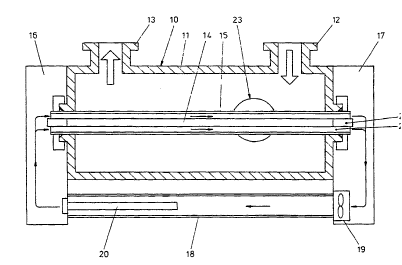
Referring to Figure 7, there is shown an alternative
ultra-violet water sterilisation chamber for use in water
treatment system of Figure l, and like parts are given like
reference numerals. A fan 43 is mounted in the compartment 16
to draw in air from outside the apparatus. A heating element
30 44 is mounted in front of the fan 43. The fan 43 and heating
element 44 are controlled by a temperature sensing element as
before, so as to direct cool or warm air along the quartz glass
sleeve 15, and thereby stabilise the air temperature inside the
quartz glass sleeve. The exhaust air is vented through a grille
45 in the compartment 17. In this way the skin temperature of
the lamp 14 is controlled to ensure maximum UV output in the
254 nM range.