Note: Descriptions are shown in the official language in which they were submitted.
- 2173$57
MAGNETIC MARKER AND PROCESS FOR MANUFACTURING
A ROLL HAVING A PLURALITY OF MAGNETIC MARKERS
ARRANGED TRANSVERSELY THEREON
FIELD OF THE INVENTION
This invention relates to a magnetic marker for use
in electronic article surveillance systems. In such systems,
an alternating magnetic field produced as an interrogatory
signal in a surveillance area evokes an article surveillance
signal from a magnetic marker affixed to articles that are
being passed through the surveillance area. This invention
also relates to a process for manufacturing a roll having a
plurality of such markers arranged transversely on the
surface of the roll.
BACKGROUND OF THE INVENTION
Electronic article surveillance systems have become
commonplace in recent years as an effective tool for retail
stores and libraries to protect against unpermitted Ler,.oval
of articles and books. For the identification of articles to
be protected, these systems rely on a detection signal issued
from a special marker affixed to said articles. There are
several kinds of detection signals, and the selection of a
suitable signal depends on the specific use. Methods of
detection are roughly divided into the following three
categories. The first approach utilizes a process which
comprises magnetizing a special soft magnetic material. The
-
21 73$51
second method makes use of an abrupt change in the impedance ~
of an LC resonant circuit at a specified frequency. The
third way concerns a signal transmission circuit that
radiates special electric waves. Among these, the first
method can supply markers at low cost and hence is
predomin~ntly used. While there are many versions of this
method, they share a common feature in that the abrupt change
which occurs in the magnetic properties of magnetic materials
upon magnetization is detected in terms of a voltage induced
in coils. Furthermore, the magnetic properties associated
with the detection include magnetostrictive vibrations, high
permeability characteristics and the squareness ratio of
hysteresis characteristics.
In the early stage of their development, magnetic
markers were of relatively large size in the form of ribbons
or wires. However, recently, in order to increase the number
of articles to which the markers can be affixed, namely to
have the markers affixed to smaller articles, there has been
a need to minimize the size of the markers. However, if an
attempt at size reduction is simply applied to ribbons or
wires, the effect of ~demagnetizing field", or the tendency
of a magnetic material to resist its own magnetization in the
direction of an applied magnetic field, increases to thereby
deteriorate the characteristics of the material as a magnetic
marker. Hence, it has been difficult to reduce the size of
-
2 1 7~S57
markers in a ribbon or wire form.
Under these circumstances, thin films of various
magnetic materials have been investigated in order to develop
compact markers. For example, JP-A-4-232594 (the term "JP-A"
as used herein means an ~unexamined published Japanese patent
application") corresponding to U.S. Patent No. 5,083,112
discloses a marker in the form of a multilayered thin film
comprising a plurality of magnetic thin films which are
interposed by nonmagnetic thin films. Each magnetic thin
film is separated from an adjacent magnetic thin film by a
nonmagnetic thin film. As a result, magnetostatic coupling
develops between adjacent magnetic thin films to sufficiently
reduce the demagnetizing field and allow for size reduction
of the marker. However, in order to fabricate the marker,
magnetic thin films must alternate with nonmagnetic thin
films, thus resulting in a complex structure. In addition,
the thickness of each nonmagnetic thin film must be
controlled with sufficient precision to assure that adjacent
magnetic thin films will be coupled magnetostatically.
However, this has often caused fluctuations in the magnetic
characteristics of the fabricated markers.
Unexamined published Japanese patent application No.
Hei. S-502962 which is based on a PCT application
(corresponding to U.S. Patent No. 5,455,563) discloses a
magnetic marker having a thin magnetic film in which the
-
~- 2 1 / 3 55 /
surface is modulated to thereby improve its magnetic
characteristics. According to this method, a sharp blade is
applied to a thin amorphous metal film on a polymer substrate
such that flaws are made at given spacings, to thereby
magnetically partition the thin metal film and to provide a
magnetic marker having satisfactory characteristics.
However, it is difficult to manufacture magnetic markers of
satisfactory characteristics in a consistent manner by
processing the surface of thin films by either mechanical or
chemical means. Moreover, the magnetic characteristics of
the marker are potentially deteriorated rather than improved.
JP-A-4-218905 (corresponding to U.S. Patent No.
5,181,020) discloses that a small thin-film magnetic marker
having satisfactory characteristics can be produced by
depositing particles on a substrate to form a thin film. The
substrate is spatially positioned relative to a target such
that the subject particles are incident at an angle with
respect to the substrate normal. In practice, magnetic
markers having satisfactory magnetic characteristics can be
obtained when thin magnetic films are fabricated on organic
polymer substrates by this method. However, the magnetic
characteristics fluctuate with the type of substrate that is
used.
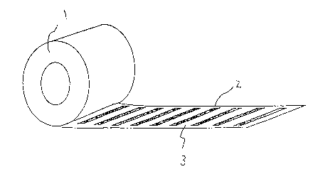
In most all cases in the prior art, markers are
successively affixed to articles by means of a dispensing
21 7~557
machine as they are peeled from the surface of a roll 1 as
shown in Fig. 2. Therein, the roll 1 has a piurality of
magnetic markers 2 arranged longitudinally on a film 3
furnished with a release paper. However, to realize faster
dispensing, there is a growing demand today for "transverse
markers", which are peeled from the surface of a roll 1 as
shown in Fig. 1. Roll 1 of Fig. l has a plurality of
magnetic markers 2 arranged transversely on a film 3
furnished with a release paper. Although the need is ever
increasing not only for transverse markers in a ribbon or
wire shape but also for those in a thin film shape, few
studies have been made to meet this need. Still less has
been described in the three prior patents discussed above.
The present inventors previously found that when an
organic polymer substrate in which the absolute value of the
difference in the degree of thermal shrinkage between
longitudinal and transverse directions ranged from 0.003 to
0.015 was used as a substrate for preparing magnetic thin
films, satisfactory uniaxial magnetic anisotropy could be
obtained. The present inventors filed JP-A-7-220971 which
describes an invention based on that finding. Magnetic
markers fabricated from such thin films display fairly good
magnetic characteristics. However, there was still a need
for further improvement.
SUMMARY OF THE INVENTION
2l 73557
The present invention has been accomplished in view
of the above circumstances. Thus, it is an object of the
present invention to provide a thin-film magnetic marker
having a simple structure and satisfactory magnetic
characteristics.
Another object of the present invention is to provide
a simple process for manufacturing a roll having a plurality
of such magnetic markers that are transversely arranged on
the surface of the roll.
In order to attain these objectives, the present
inventors continued their studies and found that magnetic
markers having satisfactory magnetic characteristics can be
obtained from appropriate combinations of a flexible organic
polymer substrate having an anisotropic thermal shrinking
property and a soft magnetic thin film having uniaxial
magnetic anisotropy. The present invention has been
accomplished on the basis of this finding.
The present inventors also found that when the
organic polymer substrate is set in such a way that the angle
formed between the direction in which the substrate has the
highest degree of thermal shrinkage and the direction of
travel of said substrate is not greater than a specified
value, and when the film-forming operation is carried out in
such a way that the thickness of the soft magnetic thin film
deposited per unit of a cathode as the result of a single
- 21 73551
pass of the organic polymer substrate over the cathode does
not exceed a specified value, a roll can easily be
manufactured having a plurality of magnetic markers with
satisfactory characteristics that are transversely arranged
on the surface of the substrate roll. The present invention
has also been accomplished on the basis of this finding.
Thus, a first aspect of the present invention relates
to a magnetic marker comprising a flexible, organic polymer
substrate and a soft magnetic thin film, characterized in
that the organic polymer substrate has an anisotropic thermal
shrinking property whereas the soft magnetic thin film has
uniaxial magnetic anisotropy. Furthermore, the angle formed
between the direction in which the organic polymer substrate
has the highest degree of thermal shrinkage and the direction
of the magnetic easy axis in the soft magnetic thin film is
in the range of from 50 to 90.
A second aspect of this invention relates to a
process for manufacturing a roll which has a plurality of
magnetic markers, each comprising an organic polymer
substrate and a soft magnetic thin film, formed transversely
on the surface of the roll by means of a combination of (i) a
roll coater method in which the organic polymer substrate
that is set on a lead-on roll is continuously fed through a
plurality of rolls as it is wound up by a take-up roll, and
(ii) a sputtering technique in which a target placed within a
- 21 73551
cathode is sputtered in a gaseous atmosphere to deposit a
thin film on the substrate. The process is further
characterized in that the organic polymer substrate is set
and transported for continuous travel in such a way that the
direction in which the organic polymer substrate has the
highest degree of thermal shrinkage is not greater than 40
with respect to the direction of travel. The process is also
characterized in that the thickness of the soft magnetic thin
film that is deposited per unit of the cathode as the result
of a single pass of the organic polymer substrate over the
cathode does not exceed 0.4 ~m.
The magnetic marker according to the first aspect of
this invention is a thin film of simple structure, yet
exhibits satisfactory magnetic characteristics. The
manufacturing process according to the second aspect of this
invention allows for continuous production of magnetic
markers having satisfactory magnetic characteristics.
Furthermore, the manufacturing process advantageously enables
easy manufacture of a roll having a plurality of such
magnetic markers arranged transversely on the surface of the
roll.
BRIEF DESCRIPTION OE THE DRAWINGS
Fig. 1 is a perspective view schematically showing a
roll having a plurality of magnetic markers arranged
transversely on the surface of the roll;
21 73~1
Fig. 2 is a perspective view schematically showing a
roll having a plurality of magnetic markers arranged
longitudinally on the surface of the roll;
Fig. 3 shows two magnetization curves (a) and (b) for
the magnetic easy and hard axes in the thin film prepared in
Example 1, respectively
Fig. 4 shows pulse voltage that were generated when
an a-c magnetic field was applied to the thin film prepared
in Example l;
Fig. 5 shows two magnetization curves (a) and (b) for
the magnetic easy and hard axes in the thin film prepared in
Example 2, respectively;
Fig. 6 shows pulse voltage that were generated when
an a-c magnetic field was applied to the thin film prepared
in Example 2;
Fig. 7 shows two magnetization curves (a) and (b) for
the magnetic easy and hard axes in the thin film prepared in
Comparative Example 1, respectively;
Fig. 8 shows two magnetization curves (a) and (b) for
the thin film of Example 4 in the transverse and longitudinal
directions of the substrate, respectively;
Fig. 9 shows pulse voltage that were generated when
an a-c magnetic field was applied to the thin film prepared
in Example 4;
Fig. 10 shows two magnetization curves (a) and (b)
2 1 73557
for the thin film of Comparative Example 2 in the
longitudinal and transverse directions, and
Fig. 11 shows two magnetization curves (a) and (b)
for the thin film of Comparative Example 3 in the
longitudinal and transverse directions of the substrate,
respectively.
DETAILED DESCRIPTION OF THE INVENTION
The present invention will now be described in detail
below.
The magnetic marker according to the first aspect of
the invention has a simple structure in that a soft magnetic
thin film is formed on a flexible, organic polymer substrate.
To attain the objects of this invention, the organic polymer
substrate necessarily has an anisotropic thermal shrinking
property, whereas the soft magnetic thin film desirably has
uniaxial magnetic anisotropy.
Also in this invention the two elements are spatially
positioned such that the angle formed between the direction
in which the organic polymer substrate has the highest degree
of thermal shrinkage and the magnetic easy axis in the soft
magnetic thin film ranges from 50 to 90, preferably from
60 to 90, more preferably from 75 to 90. If the angle
formed between the direction in which the organic polymer
substrate has the highest degree of thermal shrinkage and the
magnetic easy axis in the soft magnetic thin film is less
-- 10 --
~1 73S~/
than 50, satisfactory magnetic anisotropy cannot be imparted
to the soft magnetic thin film and the resulting magnetic
marker will have poor characteristics.
The angle ~ formed between the direction in which the
organic polymer substrate has the highest degree of thermal
shrinkage and the magnetic easy axis in the soft magnetic
thin film is 0 if the direction of r-ximum thermal shrinkage
is parallel to the magnetic easy axis. The angle ~ increases
as the relationship departs from a parallel orientation and
reaches 90 when the direction of maximum thermal shrinkage
is normal to the magnetic easy axis. Therefore, the state in
which the direction of m-ximum thermal shrinkage forms an
angle 9 with the magnetic easy axis is equivalent to the
state where they form an angle of 180 minus ~. For example,
the state where 0 is 40 is equivalent to the state where ~
is 140. Hence, the relative positional relationship between
the direction in which the organic polymer substrate has the
highest degree of thermal shrinkage and the magnetic easy
axis in the soft magnetic thin film is specified by an angle
~ of from 0 to 90, and the m~x;mum value that can be
assumed by ~ is 90.
When maximum and minimum values for the degree of
thermal shrinkage a that occurs in the organic polymer
substrate as a result of heat treatment at 150C for 15
minutes is expressed by aMAX and aMIN, respectively, the
21 73~57
difference between these two values may be taken as a figure `
of merit for the performance of the magnetic marker that uses
the organic polymer substrate. Preferably, the substrate has
a value of from 0.003 to 0.015 in terms of aMAX - aMIN
because the resulting magnetic marker has improved magnetic
characteristics. More preferably, the value of oMAX - aMIN
ranges from 0.006 to 0.01.
The degree of thermal shrinkage that occurs in the
organic polymer substrate can be varied by adjusting the
conditions of substrate preparation, and it can also be
varied by heat treating the substrate. Therefore, as long as
the difference between maximum and minimum values for the
degree of thermal shrinkage a that occurs in the organic
polymer substrate as a result of heat treatment at 150C for
15 min. ranges from 0.003 to 0.015, the substrate may be used
as prepared, or may be subsequently heated or otherwise
treated.
For measuring the degree of thermal shrinkage, the
method described in JIS C2318 may be employed except that the
heating time of a sample is changed to 15 min. Stated
specifically, five test pieces 20 mm wide and 150 mm long are
cut, and each is provided with two markings in the center at
a spacing of 100 mm. The test pieces are then left to stand
in a thermostated vessel at 150C for 15 min. and thereafter
the distance between the two markings is measured. The
- 12 -
- 21 73557
measurement is conducted for the five test pieces in a total
of 12 directions, both longitudinally and transversely, which
are varied on a pitch of 15. The degree of thermal
shrinkage is calculated by the following equation (1), and
the average is taken for the five samples to determine the
degree of thermal shrinkage o in each of the 12 stated
directions. From the data thus obtained, oMAX ( r X irum o)
and oMIN (minimum a) are selected to determine the direction
in which the organic polymer substrate has the highest degree
of thermal shrinkage.
Ll -L2
Ll ( 1 )
where L1 is the distance between the markings before heating
and L2 is the distance between the markings after heating.
The organic polymer substrate for use in the present
invention is not particularly limited as long as it is
flexible. Useful examples thereof include polyester films
such as polyethylene terephthalate ( PET), 2,6-polyethylene
naphthalate (PEN) and polyarylate (PAR), polyamide films such
as nylon 6, nylon 66 and nylon 12, polyphenylene sulfide
(PPS) films, unstretched amorphous resin films such as
polysulfone (PSF) and polyether sulfone (PES), as well as
polyimide (PI) films, polypropylene (pp) films and wholly
aromatic polyamide (APA) films. Among these, polyethylene
terephthalate (PET) films are preferably used for economic
reasons.
-
- 21 73557
The organic polymer substrate preferably has a
thickness of from 25 to 125 ~m, with the range of from 50 to
100 ~m being particularly preferred. Organic polymer
substrates thinner than 25 ~m are often difficult to handle.
If the thickness of the substrate exceeds 125 ~m, the
curvature that the substrate acquires during rolling is
difficult to eliminate even by detaching individual magnetic
markers from the surface of the roll. Therefore, substrates
thicker than 125 ~m are not suitable for use on magnetic
markers.
The soft magnetic thin film for use in the present
invention is not particularly limited as long as it has
uniaxial magnetic anisotropy. Preferably, the soft magnetic
thin film contains an amorphous phase which can acquire
uniaxial anisotropy with comparative ease, and more
preferably it contains at least 50% of such an amorphous
phase. From an economic viewpoint, Fe-based thin films are
desirable. Furthermore, while various compositions are known
to be capable of providing an Fe-based amorphous phase, as
exemplified by Fe-Si-B, Fe-P-B, Fe-P-C and Fe-Zr, thin films
containing C are particularly preferred from an economic
viewpoint. For example, Fe-C based thin films may be
prepared by reactive sputtering in a gaseous atmosphere
consisting of a mixture of an inert gas and an unsaturated
hydrocarbon gas, and the thus prepared Fe-C based thin films
- 14 -
-~ 21 73~7
allow for more economical fabrication of magnetic markers
having satisfactory magnetic characteristics. The target for
use in reactive sputtering is in no way limited to pure Fe or
Fe-C only, and commercial steel species that contain not only
Fe and C but also other elements, such as carbon tool steels,
alloy tool steels, high-speed steels and cast iron, may be
used after being worked to the shape of the target.
Furthermore, as long as the requirement for uniaxial
magnetic anisotropy is satisfied, a Co- or Ni-based thin film
that is prepared by reactive sputtering in a gaseous
atmosphere consisting of a mixture of an inert gas and an
unsaturated hydrocarbon gas may be used as the soft magnetic
thin film.
To acquire uniaxial magnetic anisotropy, a magnetic
field maybe applied to the soft magnetic thin film as it
grows during the process of thin-film formation, or the
conditions of film formation may be appropriately controlled.
Magnetic thin film preferably has a thickness of from
0.1 to 3 ~m, with the range of from 0.2 to 2 ~m being
particularly preferred. If the thickness of magnetic thin
film is below 0.1 ~m, it doesn~t exhibit an excellent soft
magnetic property. On the other hand, when the thickness of
magnetic thin film exceeds 3 ~m, it doesn~t exhibit an
excellent uniaxial anisotropy. Therefore, magnetic thin film
thinner than 0.1 ~m and thicker than 3 ~m are not suitable
- 15 -
- 21 73557
for use on magnetic markers.
The second aspect of the invention relates to a
process for manufacturing a roll having a plurality of the
above-described magnetic markers arranged transversely on the
surface thereof. The process will now be described below.
The roll shown in Fig. 1 which has a plurality of
magnetic markers according to the first aspect of this
invention arranged transversely on the surface of the roll
can be manufactured by combining a roll coater method with a
sputtering technique. The roll coater method is implemented
with a roll coater comprising three basic components, namely,
a lead-on roll, a take-up roll and a cylindrical main roll.
A continuous web of the organic polymer substrate which has
been set on the lead-on roll is continuously fed through a
plurality of rolls and successively wound up with the take-up
roll. A magnetic thin film is deposited on the substrate
while it is in contact with the surface of the main roll.
The sputtering technique is such that a target placed
within a cathode is sputtered in a gaseous atmosphere to
deposit a thin film on the substrate.
When fabricating the magnetic marker by a combination
of the roll coater method and the sputtering technique, the
organic polymer substrate is continuously transported. Also,
the substrate is set in such a way that the direction in
which the substrate has the highest degree of thermal
- 16 -
21 735~7
shrinkage forms an angle of not more than 40 with the
direction of travel of the substrate. Preferably, the
direction of maximum thermal shrinkage forms an angle of not
more than 20 with the direction of travel of the substrate,
and most preferably the subject angle is 0. If the angle
the direction of maximum thermal shrinkage forms with the
direction of substrate's travel exceeds 40, the magnetic
easy axis in the soft magnetic thin film is offset to a great
extent from the transverse direction of the substrate. As a
result, the magnetic markers arranged transversely on the
surface of a roll will not have the intended uniaxial
magnetic anisotropy, and hence will exhibit poor
characteristics.
The angle ~ formed between the direction in which the
organic polymer substrate has the highest degree of thermal
shrinkage and the direction of travel of the substrate is 0
if the direction of maximum thermal shrinkage is parallel to
the direction of travel of the substrate. The angle
increases as the relationship departs from a parallel
orientation and reaches 90 when the direction of m~ximum
thermal shrinkage is normal to the direction of travel of the
substrate. Therefore, the state in which the direction of
m~x; mum thermal shrinkage forms an angle ~ with the direction
of travel of the substrate is equivalent to the state where
they form an angle of 180 minus ~. For example, the state
-
21 73557
where 9 is 40 is equivalent to the state where ~ is 140.
Hence, the positional relationship between the direction in
which the organic polymer substrate has the highest degree of
thermal shrinkage and the direction of travel of the
substrate is specified by an angle ~ of from 0 to 90, and
the maxirllm value that can be assumed by ~ is 90.
When fabricating the magnetic marker by a combination
of the roll coater method and the sputtering technique, the
thickness of the soft magnetic thin film that is deposited
per unit of the cathode as the result of a single pass of the
organic polymer substrate over the cathode should not exceed
0.4 ~m. The preferred thickness is 0.2 ~m or below. If the
thickness of the soft magnetic thin film that is deposited
per unit of the cathode as the result of a single pass of the
organic polymer substrate over the cathode exceeds 0.4 ~m,
the resulting thin film not only has deteriorated soft
magnetic material characteristics but also does not exhibit
satisfactory uniaxial magnetic anisotropy.
A soft magnetic thin film thicker than 0.4 ~m may be
prepared by passing the organic polymer substrate several
times over the cathode while ensuring that a film no thicker
than 0.4 ~m forms per unit of the cathode as the result of a
single pass of the substrate over the cathode.
To implement the manufacturing process of the
invention, a continuous web of the organic polymer substrate
-
21 73~57
is first set on the lead-on roll from which it is delivered
and transported for continuous travel. A soft magnetic thin
film is deposited on the substrate while the substrate is in
contact with the surface of the cylindrical main roll. To
this end, one or more units of the cathode may be provided
under the main roll.
The sputtering apparatus used to fabricate the soft
magnetic thin film having uniaxial magnetic anisotropy in the
present invention is not particularly limited, and useful
examples are an r-f diode sputtering apparatus, a d-c
sputtering apparatus, a magnetron sputtering apparatus, a
triode sputtering apparatus and an ion-beam sputtering
apparatus, as well as a sputtering apparatus having opposed
targets. Among these, a magnetron sputtering apparatus is
advantageously used with those organic polymer films having
relatively low heat resistance since they permit faster
deposition rates of thin films while effectively retarding
elevation of the substrate temperature.
In magnetron sputtering, an electric field is applied
to the target as a cathode, and a magnetic field is applied
in a direction normal to the electric field so as to cause
the cyclotron movement of the charged particles in plasma.
This improve the sputtering yield, and the particles of the
sputtered target are deposited on the substrate.
The magnetic field that is applied to cause the
-- 19 --
- 21 735~7
cyclotron movement of the charged particles may be supplied
in the form of a leakage field from a permanent magnet or an
electromagnet that is placed beneath the target.
Alternatively, a yoke may be connected to the permanent
magnet or electromagnet such that a magnetic flux is directly
induced above the target surface to thereby enhance the
leakage field.
The conditions for preparing a soft magnetic thin
film in a gaseous atmosphere vary with the size of the
deposition chamber and the evacuating capacity of the vacuum
pump that is used. The ultimate vacuum to be reached within
the deposition chamber during thin film formation is
preferably 5x10⁻⁶ torr or below, more preferably lx10-6 torr
or below. A mixture of an inert gas and an unsaturated
hydrocarbon gas is preferably used as the gas that is
supplied to the vacuum chamber during thin film formation.
Examples of the inert gas include argon, helium and neon. A
commercially available unsaturated hydrocarbon gas is
acceptable, and examples thereof include acetylene, allene,
isobutylene, ethylene, 1,3-butadiene, 1-butene, propylene and
methyl acetylene. The inert gas is suitably set to a flow
rate of from 20 to 200 CCM, preferably from 40 to 170 CCM,
more preferably from 60 to 150 CCM. The unsaturated aromatic
hydrocarbon gas is suitably set to a flow rate of from 0.5 to
30 CCM, preferably from 2 to 25 CCM, more preferably from 5
- 20 -
2 1 7 3~51
to 20 CCM.
The following Examples and Comparative Examples are
provided for the purpose of further illustrating the present
invention, but are in no way to be taken as limiting.
EXAMPLE 1
A continuous thin Fe-C film was deposited in a
thickness of 0.4 ~m on a substrate by means of a d-c
magnetron sputtering apparatus. The substrate was a square
polyethylene terephthalate film (UNITIKA, LTD.) 100 ~m thick
and 100 mm long on each side. For film deposition, permanent
magnets were placed on both sides of the substrate such that
the magnets were substantially normal to the direction in
which the substrate had the highest degree of thermal
shrinkage. Iron (99.9% pure) was used as a target for
sputtering which was conducted in a gaseous mixture of Ar
(flow rate: 150 CCM) and C2H4 (15 CCM) at a sputtering gas
pressure of 1.5x10⁻³ torr with sputtering power supplied at 7
kW.
The magnetic easy axis in the deposited thin Fe-C
film formed an angle of 85 with the direction in which the
substrate (polyethylene terephthalate film) had the highest
degree of thermal shrinkage.
The cyclic magnetization characteristics of the thin
Fe-C film were measured with a magnetic hysteresis loop
tracer AC BH-lOOK (Riken Denshi Co., Ltd.) at a frequency of
- 21 73~S7
60 Hz. The results are shown in Fig. 3, which plots the
applied magnetic field on the horizontal axis and the degree
of magnetization on the vertical axis. Curve (a) shows the
magnetization that developed along the magnetic easy axis,
and curve (b) shows the magnetization along the magnetic hard
axis. As seen from Fig. 3, a loop of high squareness ratio
having a coercive force of 0.6 Oe was obtained along the
magnetic easy axis, whereas the magnetization changed
linearly with the applied field along the magnetic hard axis.
Thus, the thin Fe-C film acquired a very high degree of
uniaxial magnetic anisotropy.
The structure of the thin film was identified with an
X-ray diffractometer RAD-RB (Rigaku Denki Co., Ltd), and it
exhibited a halo pattern characteristic of amorphous
structures.
To evaluate its performance as a magnetic marker, the
thin film was cut to a rectangular shape 5 mm wide and 30 mm
long such that the magnetic easy axis was aligned in the
longitudinal direction, and a cyclic magnetic field of 1.5 Oe
was applied at 60 Hz. The resulting pulse voltage were
measured in terms of the voltage that was induced at a
detection coil wound about the thin film. The results are
shown in Fig. 4, which plots the sweep time on the horizontal
axis and the voltage on the vertical axis. As seen from Fig.
4, the magnetic marker prepared in Example 1 had a sharp
- 22 -
- 2173~7
pulse characteristic, thus indicating its superior magnetic
characteristics.
EXAMPLE 2
A continuous thin Fe-C film was deposited in a
thickness of 0.3 ~m on a substrate by means of a d-c
magnetron sputtering apparatus. The substrate was a square
polyethylene terephthalate film (UNITIKA, LTD.) that was 75
~m thick and 100 mm long on each side. The difference
between aMAX and aMIN was 0.007, with aMAX and oMIN being
m-x;mum and minirum values, respecti~ely, for the degree of
thermal shrinkage a that occurred as a result of heat
treatment at 150C for 15 min. A commercial alloy tool steel
(JIS designation: SKS 3) was used as a target for sputtering
which was conducted in a gaseous mixture of Ar (flow rate:
150 CCM) and C2H4 (15 CCM) at a sputtering gas pressure of
1.5x10⁻³ torr with sputtering power supplied at 7 kW.
The magnetic easy axis in the deposited thin Fe-C
film formed an angle of 75 with the direction in which the
substrate (polyethylene terephthalate film) had the highest
degree of thermal shrinkage.
The cyclic magnetic characteristics of the thin Fe-C
film were measured as in Example 1. The results are shown in
Fig. 5, which plots the applied magnetic field on the
horizontal axis and the degree of magnetization on the
vertical axis. Cur~e (a) shows the magnetization that
2 1 7 3557
developed along the magnetic easy axis, and curve (b) shows
the magnetization along the magnetic hard axis. As seen from
Fig. 5, a loop of high squareness ratio having a coercive
force of 0.6 Oe was obtained along the magnetic easy axis,
whereas the magnetization changed linearly with the applied
field along the magnetic hard axis. Thus, the thin Fe-C film
acquired a degree of uniaxial magnetic anisotropy that was as
high as that of the thin film prepared in Example 1.
The structure of the thin film was identified by the
same method as in Example 1, and it exhibited a halo pattern
characteristic of amorphous structures.
To evaluate its performance as a magnetic marker, the
thin film was cut to a rectangular shape 5 mm wide and 30 mm
long such that the magnetic easy axis was aligned in the
longitudinal direction. The pulse voltage that developed
upon field application as in Example 1 were measured in terms
of the voltage that was induced at a detection coil wound
about the thin film. The results are shown in Fig. 6, which
plots the sweep time on the horizontal axis and the voltage
on the vertical axis. As seen from Fig. 6, the magnetic
marker prepared in Example 2 also had a sharp pulse
characteristic, thus indicating its superior magnetic
characteristics.
EXAMPLE 3
A continuous thin Fe-Si-B-C film was deposited in a
- 24 -
2173~57
thickness of 0.4 ~m on a substrate by means of a d-c
magnetron sputtering apparatus. The substrate was a square
polyethylene terephthalate film (UNITIKA, LTD.) that was 100
~m thick and 100 mm long on each side. The difference
between aMAX and aMIN was 0.01, with aMAX and aMIN being
maximum and minimum values, respectively, for the degree of
thermal shrinkage a that occurred as a result of heat
treatment at 150C for 15 min. For film deposition,
permanent magnets were placed on both sides of the substrate
such that the magnets were substantially normal to the
direction in which the substrate had the highest degree of
thermal shrinkage. An alloy system Fe-Si-B was used as a
target for sputtering which was conducted in a gaseous
mixture of Ar (flow rate: 200 CCM) and C3H6 (10 CCM) at a
sputtering gas pressure of 2.0x10⁻³ torr with sputtering
power supplied at 8 kW.
The magnetic easy axis in the deposited thin Fe-Si-B-
C film formed an angle of 65 with the direction in which the
substrate (polyethylene terephthalate film) had the highest
degree of thermal shrinkage.
The cyclic magnetic characteristics of the thin Fe-
Si-B-C film were measured as in Example 1. A loop of high
squareness ratio having a coercive force of 0.3 Oe was
obtained along the magnetic easy axis, whereas the
magnetization changed linearly with the applied field along
- 2173557
the magnetic hard axis. Thus, the thin Fe-Si-B-C film
acquired a degree of uniaxial magnetic anisotropy that was as
high as that of the thin film prepared in Example 1.
The structure of the thin film was identified by the
same method as in Example 1, and it exhibited a halo pattern
characteristic of amorphous structures.
To evaluate its performance as a magnetic marker, the
thin film was cut to a rectangular shape 5 mm wide and 30 mm
long such that the magnetic easy axis was aligned in the
longitudinal direction. The pulse voltage that developed
upon field application as in Example 1 were measured in terms
of the voltage that was induced at a detection coil wound
about the thin film. The magnetic marker prepared in Example
3 also had a sharp pulse characteristic, thus indicating its
superior magnetic characteristics.
COMPARATIVE EXAMPLE 1
A continuous thin Fe-C film was deposited in a
thickness of 0.4 ~m on a polyethylene terephthalate film of
the same dimensions as in Example 1 using a d-c magnetron
sputtering apparatus. For film deposition, permanent magnets
were placed on both sides of the substrate such that the
magnets formed an angle of 30 with the direction in which
the substrate had the highest degree of thermal shrinkage.
The target and sputtering conditions were the same as in
Example 1.
~1 73$57
The magnetic easy axis in the deposited thin Fe-C
film formed an angle of 40 with the direction in which the
substrate (polyethylene terephthalate film) had the highest
degree of thermal shrinkage.
The cyclic magnetization characteristics of the thin
Fe-C film were measured as in Example 1. The results are
shown in Fig. 7, which plots the applied magnetic field on
the horizontal axis and the degree of magnetization on the
vertical axis. Curve (a) shows the magnetization that
developed along the magnetic easy axis, and curve (b) shows
the magnetization along the magnetic hard axis. The film
exhibited a soft magnetic characteristic (0.7 Oe) along the
magnetic easy axis but a loop of high squareness ratio was
not obtained. Moreover, the magnetization did not linearly
change with the applied field along the magnetic hard axis,
indicating that the film did not acquire satisfactory
uniaxial magnetic anisotropy.
To evaluate its performance as a magnetic marker, the
thin film was cut to a rectangular shape 5 mm wide and 30 mm
long such that the magnetic easy axis was aligned in the
longitudinal direction, and the pulse voltage that developed
upon field application as a Example 1 were measured in terms
of the voltage that was induced at a detection coil wound
about the thin film. A satisfactory pulsed voltage was not
obtained under the stated conditions. Hence, the magnetic
21 7 3$57
marker of Comparative Example 1 did not have satisfactory
magnetic characteristics.
EX~MPLE 4
A continuous Fe-C film 50 m long was deposited in a
thickness of 0.5 ~m on a polyethylene terephthalate substrate
film 75 ~m thick and 100 cm wide (UNITIRA, Ltd.) by a roll
coater method with a d-c magnetron sputtering apparatus. The
film was set on a lead-on roll such that the direction in
which the film had the highest degree of thermal shrinkage
formed an angle of 0 with (i.e., was parallel to) the
direction of its travel, and the film was continuously
transported over a cylindrical main roll. A single unit
cathode was placed beneath the main roll, and the thickness
of the Fe-C film that was deposited as the result of a single
pass of the substrate over the cathode was set at 0.05 ~m.
The substrate was passed over the cathode 10 times to provide
a final film thickness of 0.5 ~m. Iron (99.9% pure) was used
as a target for sputtering which was conducted in a gaseous
mixture of Ar (flow rate: 150 CCM) and C2H4 (20 CCM) at a
sputtering gas pressure of 1.8x10⁻³ torr with sputtering
power supplied at 8 kW.
The magnetic easy axis in the deposited thin Fe-C
film formed an angle of 85 with the direction of substrate
travel (i.e., the direction of its m~x;mum thermal
shrinkage).
- 28 -
-
21 73557
.
The cyclic magnetic characteristics of the thin Fe-C
film were measured as in Example 1. The results are shown in
Fig. 8, which plots the applied magnetic field on the
horizontal axis and the degree of magnetization on the
vertical axis. Curve (a) shows the magnetization that
developed in the transver8e direction of the substrate, and
curve (b) shows the magnetization in the longitudinal
direction. As seen from Fig. 8, the deposited film acquired
a magnetic easy axis in the transverse direction of the
substrate, to thereby produce a loop of high squareness ratio
having a coercive force of 0.5 Oe. On the other hand, the
magnetization in the longitudinal direction of the substrate
changed linearly with the applied field. Thus, the thin Fe-C
film acquired a very high degree of uniaxial magnetic
anisotropy.
The structure of the thin film was identified by the
same method as in Example 1, and it exhibited a halo pattern
characteristic of amorphous structures.
For the ultimate purpose of obtaining a plurality of
magnetic markers arranged transversely as shown in Fig. 1, a
sample 5 mm wide and 30 mm long was cut out of the continuous
thin Fe-C film such that the sample width (as measured in the
transverse direction) was oriented parallel to the
longitudinal direction of the thin film (i.e., the direction
of substrate travel). The pulse voltage that developed upon
21 73557
field application as in Example 1 were evaluated in terms of
the voltage that was induced at a detection coil wound about
the thin film. The results are shown in Fig. 9, which plots
the sweep time on the horizontal axis and the voltage on the
vertical axis. As seen from Fig. 9, the magnetic marker
prepared in Example 4 had a sharp pulse characteristic, thus
indicating its superior magnetic characteristics. In another
experiment, 10 samples were taken at spacings of 5 m along
the length of the thin film (parallel to the travel path of
the substrate) and evaluated for pulse characteristics by the
same method. Each sample had a sharp pulse characteristic
that was almost comparable to all the other samples. Thus, a
roll was manufactured having a plurality of magnetic markers
with superior magnetic characteristics arranged transversely
on the surface.
COMPARATIVE EXAMPLE 2
A continuous Fe-C film 50 m long was deposited in a
thickness of 0.5 ~m under the same conditions as in Example
4, except that the substrate was a polyethylene terephthalate
film (UNITIKA, LTD.) that was set on a lead-on roll such that
the direction in which it had the highest degree of thermal
shrinkage formed an angle of 60 with the direction of
travel.
The magnetic easy axis in the deposited thin Fe-C
film formed an angle of 20 with the direction of substrate
- 30 -
-
21 7 ~5'~ l
travel and an angle of 40 with the direction for the maximum
thermal shrinkage of the substrate.
The cyclic magnetic characteristics of the thin Fe-C
film were measured as in Example 1. The results are shown in
Fig. 10, which plots the applied magnetic field on the
horizontal axis and the degree of magnetization on the
vertical axis. Curve (a) shows the magnetization that
developed in the longitudinal direction of the substrate, and
curve (b) shows the magnetization in the transverse
direction. As seen from Fig. 10, the magnetization did not
change linearly with the applied field in either direction.
It was therefore clear that the thin Fe-C film prepared in
Comparative Example 2 did not acquire as high a degree of
uniaxial magnetic anisotropy as the sample prepared in
Example 4. It should also be mentioned that compared to the
longitudinal direction of the substrate, the thin film did
not have a magnetic easy axis in the transverse direction of
the substrate.
For the ultimate purpose of obtaining a plurality of
transversely arranged magnetic markers from the continuous
thin Fe-C film, a sample 5 mm wide and 30 mm long was cut
such that the sample width (as measured in the transverse
direction) was oriented parallel to the longitudinal
direction of the thin film (i.e., the direction of substrate
travel). The pulse voltage that developed upon field
- 31 -
21 7~557
application as in Example 1 were evaluated in terms of the
voltage that was induced at a detection coil wound about the
thin film. A pulsed voltage was not obtained under the
stated conditions.
COMPARATIVE EXAMPLE 3
A continuous Fe-C thin film 50 m long was deposited
in a thickness of 0.5 ~m by repeating the procedure of
Example 4, except that the thickness of the Fe-C thin film
that was deposited as the result of a single pass of the
substrate over the cathode was set at 0.5 ~m. The target and
the sputtering conditions were also the same as in Example 4.
The magnetic easy axis in the deposited thin Fe-C
film formed an angle of 40 with the direction of substrate
travel (i.e., the direction of its m-ximum thermal
shrinkage).
The cyclic magnetic characteristics of the thin Fe-C
film were measured as in Example 1. The results are shown in
Fig. 11, which plots the applied magnetic field on the
horizontal axis and the degree of magnetization on the
vertical axis. Curve (a) shows the magnetization that
developed in the longitudinal direction of the substrate, and
curve (b) shows the magnetization in the transverse
direction. As seen from Fig. 11, the magnetization did not
change linearly with the applied field in either direction.
It was therefore clear that the thin Fe-C film prepared in
- 32 -
-
21 7~57
Comparative Example 3 did not acquire as high a degree of
uniaxial magnetic anisotropy as the sample prepared in
Example 4. It should also be mentioned that the thin film
exhibited poor soft magnetic characteristics as evidenced by
a coercive force of 1.5 Oe in the Iongitudinal direction of
the substrate. Moreover, a loop of high squareness ratio was
not obtained.
The structure of the thin film was identified by the
same method as in Example 1, and it exhibited not only a halo
pattern characteristic of amorphous structures but also a
sharp peak characteristic of crystal structures.
For the ultimate purpose of obtaining a plurality of
transversely arranged magnetic markers from the continuous
thin Fe-C film, a sample 5 mm wide and 30 mm long was cut
such that the sample width (as measured in the transverse
direction) was oriented parallel to the longitudinal of the
thin film (i.e., the direction of substrate travel). The
pulse voltage that developed upon field application as in
Example 1 were evaluated in terms of the voltage that was
induced at a detection coil wound about the thin film. A
pulsed voltage was not obtained under the stated conditions.
While the invention has been described in detail and
with reference to specific embodiments thereof, it will be
apparent to one skilled in the art that various changes and
modifications can be made therein without departing from the
21 7~5~7
.
spirit and scope thereof.
- 34 -