Note: Descriptions are shown in the official language in which they were submitted.
2I'~3~2~
WO 95110724 PCT/US94I11222
MIZINa VALVE BAVINa A BALL VALVE CARTZtIDGE
AND A LOWER INSERT NE1LBEZt
TECHNICAL FIELD
The field of this invention relates to a mixer
valve for a faucet incorporating a movable valve element
housed in a cartridge and more particularly to a ball
valve element housed in a cartridge.
BACKGROUND OF THE DISCLOSURE
Single handle faucets, commonly referred to as
mixer valves, that control both hot and cold water flow
have seen vast consumer acceptance. These faucets are
commonly constructed such that a handle or knob is
movable in two distinct directions to adjust the mix of
hot and cold water and to adjust the volume or flow
rate.
The two basic types of mixer valves that have
seen widest commercial acceptance are plate valves and
ball valves. While ball valves offer a reliable compact
construction that is durable, plate valves offer a drive
mechanism that allows motion to the handle in two
desirable directions most universally accepted by
consumers. The desirable handle motion allows for an
orbiting motion of the handle about a fixed longitudinal
axis of the valve body and a rocking, i.e. pivoting,
motion about a movable horizontal axis relative to the
valve body. The horizontal axis is perpendicular to the
longitudinal axis of the valve body and is fixed with
respect to the handle such that it moves about the
housing as the handle rotates about the fixed
longitudinal axis. The one distinguishing
characteristic of this type of handle motion is that
when the handle is pivoted to an off position, the
desired mix ratio of hot and cold water can be
remembered by the location of the handle so that when
the faucet is turned back on, the same mix of hot and
cold water flows through the faucet.
217362
-2-
Recently, ball valves have been devised that allow
the handle to be operated in the same fashion as the
commercially accepted plate type mixer valve. Some of these
ball type mixer valves require the introduction of another
moving part in the form of a rotatable plate mounted above the
ball valve element. Furthermore, these ball valves have been
combined with plate devices which can be adjustably positioned
about a cover opening through which the handle controls the
ball valve to limit the total flow rate. Alternately or in
addition, these limiting devices limit the maximum ratio of
hot water to cold water and consequentially the maximum
temperature of the mixed water at the outlet.
Various disadvantages exist with the above mentioned
ball valve construction. In particular, the ball valve
element is mounted between elastomeric inlet port seals
positioned about the inlet ports of the valve body and a
sealing gasket that is mounted under the valve cover or cap.
The elastomeric port seals and gasket are all yielding and
render a floating characteristic to the ball valve element
between the valve body and cap. There is no positive lock ar
locator mechanism that securely positions the ball valve in
place. Because the ball valve can be moved in a translational
manner against the elastomeric elements, the operator when
operating the handle can also move the handle a small amount
in any direction including directions not contemplated in the
design of the mixing valve. This unwanted motion renders an
68085-598
-2a- 2 ~ 73628
undesirable spongy feel to the operation of the faucet and an
uncertainty to the operator as to the proper operation of the
faucet. Furthermore, the spongy feel of the
68086-598
WO 95110724 PCT/US94/11222
- 3 -
handle gives the impression that the handle is unstable
and not assembled properly.
The top sealing gasket provides three
functions. Firstly, it seals against leakage of water
about the ball. Secondly, its outer periphery seals
against the inner surface of the housing to prevent
leakage. Thirdly, the gasket resiliently positions the
ball downwardly against the inlet seals. As a
consequence, the gasket is an expensive component due to
its mass and shape. To obtain a smooth operation, the
elastomeric sealing gasket has a thin layer of
tetraflouroethylene that contacts the ball valve to
reduce wear as compared to direct contact of the
elastomeric material with the ball member.
In order to reduce the floating feel, a
regulation ring has been incorporated in many ball valve
mixing valves. The regulation ring is adjustably
screwed onto the valve cap. the regulation ring pushes
the sealing gasket downward against the ball valve
element which in turn is pressed against the inlet
seals. The downward placement of the sealing gasket and
ball valve element reduces the undesirable motion but
does not eliminate it. Furthermore, the combining of
the regulation ring with the known gasket increases the
cost and complexity of the mixing valve. The increased
pressure exerted in the sealing gasket wears the gasket
down. As wear and tear progresses, the regulation ring
must be repeatedly adjusted to restore pressure on the
gasket to both seal and provide the handle with an
operating resistance that maintains it in a stable
position against gravitational forces exerted on a
faucet handle.
WO 95/10724 PCTIUS94/11222
- 4 -
Another ball construction which mimics the
desirable handle motion of known plate valves is
disclosed in my PCT publication WO 92/22765 published on
December 23, 1992 which incorporates a horizontal pin
extending through the ball valve to position the ball in
the housing. This construction virtually eliminates the
floating or spongy feeling during operation of the ball
valve faucet.
Cartridges for the valve elements and seals
have also been commercially popular. Known cartridges
have housed the movable and fixed plate. The cartridge
can easily be removed and replaced with another in order
to effect an easy repair to the faucet. After the water
supply is.turned off, the faucet is merely opened and
the cartridge is easily replaced. This type of repair
can be accomplished without the need to call in skilled
labor.
Plate valves have often been incorporated into
a cartridge format. However, ball valves have not been
amenable to a cartridge construction. Firstly, the
floating nature of the traditional ball valve demanded
that any cartridge completely surround and capture the
ball valve, otherwise the ball valve simply falls out of
the bottom of the cartridge. Secondly, the compact
nature of the ball valve construction leaves little room
for the inclusion of a cartridge. The introduction of
traditional cartridges that house and capture the ball
into the faucet housing demands that the housing be made
taller to incorporate the added height needed for the
inclusion of the cartridge.
Furthermore, traditional cartridges inhibit
repair to worn elastomeric seals. The cartridge houses
~ ~ ~~6~
-5-
both the moving valve element and the fixed valve ports which
often include the elastomeric port seals. Most of the wear
and resulting leakage in a faucet is the result of the
repetitive motion of the moving valve element on the
elastomeric port seals. Because the seals are encased in the
cartridge, the entire cartridge is replaced including the
replacement of many good cartr~.dge components that still have
long useful lives. The desire to eliminate waste however is
offset by the need to simplify the repair operation.
Furthermore, many cartridges are permanently assembled and do
not permit dismantling.
Even for cartridges that can be dismantled, the
advantages of a cart ridge is lost if the cart ridge was
dismantled into all of its component parts. The movable valve
element falls out and is often not replaced in its correct
orientation. This misinstallation can easily occur for
symmetrical plate valves and ball valves which are inherently
symmetrical. It takes a knowledgeable and skilled person to
avoid mounting ceratin ball valves in a cartridge in its
incorrect orientation.
What is needed is a ball valve cartridge for a mixer
valve that houses the upper sealing elements that seal against
leakage to the exterior of the housing and seats a ball valve
element but allows access to the elastomeric port seals about
the inlet ports. What is also needed is a cartridge that
~.~
68086-598
-5a-
seats the movable ball valve element and allows the ball valve
to operationally engage a faucet insert that has two valve
inlets therethrough that is seated in the faucet body. What
is also needed is a ball valve cartridge assembly that can
68086-598
CA 02173628 2000-07-17
68086-598
6
be opened to provide access to the elastomeric seals while
retaining the ball valve in a mounted and installed condition
with the cartridge.
SUMMARY OF THE DISCLOSURE
The invention provides in a faucet mixer valve having
a movable valve element mounted in a housing body that defines
a cavity, said body having a plurality of inlet ports and an
outlet port in fluid communication with said cavity, said
movable valve element cooperating with said inlet ports to
control liquid flow in both flow rate and temperature mix
through said ports, said valve body having a control opening
therethrough, said valve element having a control stem
connected thereto and extending through said control opening,
the improvement characterized by: said body including a lower
base member having hot and cold supply passages and an outlet
passage, said body having a substantially cylindrical cavity
with a planar bottom; said body including an insert member
fitted in a lower section of said cavity of said lower base;
said insert member having respective inlet ports aligned for
fluid communication with said hot and cold supply passages in
said base member and having a respective outlet port in fluid
communication with said outlet passage; said insert member
having a recess in its upper end for operably receiving said
movable valve element to cooperate with said inlet ports; said
mixer valve being in cartridge form with a cartridge having a
housing member; said cartridge housing member having an upper
opening for allowing said control stem passing therethrough;
means for seating said movable valve element to said cartridge
housing member; said cartridge having a lower opening through
which said movable valve element protrudes into said recess in
said insert member to be cooperative to said inlet ports; said
cartridge housing having a seal seat about said upper opening;
and a sealing gasket seated in said seal seat about said upper
CA 02173628 2000-07-17
68086-598
7
opening in said cartridge housing and sealingly abuttable
against said movable valve element.
The movable valve element may be a ball valve
pivotably mounted in the valve receiving cavity of a housing.
The ball valve has at least a partially spherical surface and a
plurality of inlet openings in its surface. The openings
cooperate with the ports to control fluid flow through the
ports. The valve housing has a control opening. The ball
valve has a control stem passing through the control opening.
The ball valve is pivotably mounted to a cartridge
housing. The mixer valve has a cavity which is sized to house
the cartridge housing. The cartridge has a lower opening
through which said ball valve element protrudes to be
cooperative with the inlet ports such that the ball valve
element directly abuts elastomeric inlet port seals housed at
the downstream end of inlet ports.
In one embodiment of the invention, the faucet body
includes a lower base member, a cover assembly and a valve seat
insert received in the lower base member. The insert has the
inlet ports passing therethrough and seats the elastomeric port
seals at the downstream end. Preferably, the outlet port also
passes through the insert. The insert preferably is made from
moldable plastic. The insert is preferably equipped with a
retention device that retains the insert seated in the faucet
body.
In an alternate embodiment, the insert can be
removably fastened to the cartridge such that a conventional
looking cartridge assembly appearance is achieved. However,
when the insert is removed, the integrity of the movable valve
element being secured to the cartridge is maintained while
providing access to the eleastomeric port seals.
CA 02173628 2000-07-17
68086-598
7a
In this fashion, a valve element is incorporated into
a valve cartridge without necessitating an increase in the
overall height of the valve body. Furthermore, the seal that
prevents leakage about the movable valve element and cartridge
can have a minimal size and weight because the upper gasket
seal no longer has the double function of biasing and
positioning the movable valve element against the inlet port
seals.
WO 95110724 PCT/US94/11222
BRIEF DESCRIPTION OF THE DRAWINGS
Reference now is made to the accompanying
drawings in which:
Figure 1 is a side elevational and segmented
view of a mixer valve illustrating one embodiment of the
invention;
Figure 2 is an exploded perspective view of
the mixer valve shown in Figure 1;
Figure 3 is a partially cross-sectional view
of the cartridge member taken along line 3-3 shown in
Figure 1;
Figure 4 is a fragmentary cross-sectional view
of the taken along line 4-4 shown in Figure 2 further
illustrating the insert member:
Figure 5 is a bottom plan view of the
cartridge shown in Figure 2;
Figure 6 is a top plan view of the cartridge
housing shown in Figure 2;
Figure 7 is a cross-sectional view of the
gasket shown in Figure 1 in an unloaded condition; and
Figure 8 is a segmented view of an alternate
embodiment illustrating a cartridge assembly including
a modified insert attached to a modified cartridge.
DETAILED DESCRIPTION OF THE PREFERRED EMBODIMENT
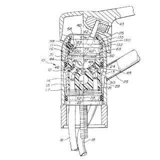
Referring to Figures 1, 2, and 4, a mixer
valve 10 includes a valve housing 12 that is formed from
a lower base member 14 and a cover assembly 16. The
base member 14 has a substantially cylindrical cavity 22
formed therein with two inlet passages 18 and 19 at a
flat bottom end 23 for cold and hot water and an outlet
~ 7:~~2~
passage 20 through a side cylindrical wall 21 for the passage
of mixed water from cavity 22.
A conventional tubular shell 17 is sealingly and
slidably mounted about the lower base member 14 and forms an
annular chamber 15 in fluid communication with the outlet
passage 20. A spout 25 is affixed to the shell and in fluid
communication with the annular chamber 15 through aperture 13
in shell 17. The cover assembly 16 includes a threaded member
31 that is screwed onto the base member 14. A cosmetic shell
11 is positioned over the member 31.
The lower base member 14 is fitted with an insert
member 44. Insert member 44 has respective inlet ports 45 and
46 that are aligned with inlet passages 18 and 19. The
upstream ends of inlet ports 45 and 46 are counter bored to
receive o-rings 47 at the upstream end. O-rings 47 seal up
against the end of passages 18 and 19 to provide a leak free
connection between passage 18 and port 45 and between passage
19 and port 46. The downstream ends of ports 45 and 46 are
counter-bored to form a seat for two biasing springs 48 which
bias tubular elastomeric sealing elements 49 against the ball
valve element 24. The holes therethrough have a diameter of
approximately 6.5 mm. The ports 45 and 46 have their
downstream ends positioned at approximately 40° up from the
bottom point 51 of concavely formed semi-spherical cavity 50.
Furthermore, the ports 45 and 46 are circumferentially
68086-598
2173628
positioned approximately 15° from the fore and aft plane as
measured from the vertical axis 28.
The outlet port 52 extends downwardly from the semi-
spherical recess 50 and through the side wall 55 of the insert
to be alignable with passage 20 of the base member 14. Top
wall 53 may have an upwardly extending lug or key 54.
The insert member 44 is made from easily molded
plastic material. The molding of plastic insert 44 provides
for an expeditious method to make the bent ports 45 and 46
inclined from their inlet ends to their downstream ends. Even
if the insert 44 is made from metal, the easy accessibility of
ports 45, 46, and 52 provide for greater design flexibility
and ease of manufacturing the ports 45, 46, and 52 as compared
to previous faucets when the ports 45, 46, and 52 are formed
directly in lower base member 14.
The semi-spherical valve recess 50 is sized to
receive a ball valve element 24 that is housed in a cartridae
26. The cover 16 affixes the cartridge 26 in the cavity 22.
The base member 14 has an upright collar flange 70 with a
keyed slot 71 that receives a key 72 of cartridge housing
member 56 to correctly orient the cartridge 26 in the mixer
valve 10. As shown in Figure 5, the cartridge has a hole 73
in its bottom edge 77 to receive key 54 of insert member 44
such that the insert member 44 is rotationally aligned in its
correct position.
68086-598
2 i 7 ~~2~3
-11-
The ball valve element 24 has a substantially
spherical valve surface 29 with cold inlet openings 30 and 32,
hot inlet openings 34 and 36, and outlet opening 38
therethrough. The shape of the surface 29 substantially
complements the concave contour of recess 50. The openings 30
and 32 cooperate with the cold inlet port 45, openings 34 and
36 cooperate with hot inlet port 46, and outlet opening 38
cooperates with outlet port 52 respectively to regulate the
mixture ratio of water and the flow rate, i.2. volume of total
water per unit time from the two inlet ports 45 and 47 to the
out let port 52 .
The cover assembly 16 has a control opening 40
therethrough. The cover 16 is positioned such that the
longitudinal axis 28 of the valve housing 12 passes through
the control opening 40. The cartridge housing member 56 has
an upper opening 58 aligned under opening 40.
A control stem 42 is fixedly connected to the ball
valve element 24. A control stem 42 extends through the
control opening 40. The control stem 42 is constructed to be
attached to a faucet handle 43 in a conventional fashion.
The ball valve element 24 is pivotably mounted to
the cartridge housing member 56. The housing member 56 may be
manufactured from known plastic material suitable for faucet
applications. The ball valve element 24 also has a
cylindrical pin 60 extending therethrough with its distal ends
62 extending to the exterior of ball valve surface 29. Holes
61 are sized to slidably receive the pin 60. The pin 60 is
68086-598
~ 11362
-lla-
positioned to intersect the center 66 of ball valve 24 and lie
perpendicular to control stem 42. The pin can be welded in
place to ball valve element 24 as described in more detail
later.
Each distal end 62 is positioned in a
circumferentially disposed slot 68 formed in the cartridge
housing 56. As shown in Figure 3, each slot 68 has a central
axis disposed in a plane 69 perpendicular to axis 28. Because
the ends 62 are cylindrical in shape, they have a circular
cross-section
68086-598
WO 95110724 ~~ ~ PCT/US94/11222
- 12 -
that allows them to pivot in slots 68 about an axis 75
that is perpendicular to axis 28.
The circumferential ends 74 of the slots 68
form stop shoulders 76 for the distal ends 62. The
slots 68 are vertically dimensioned to form only enough
clearance to allow sliding movement of the pin ends 62
in slot 68. Desirably no vertical spacing exists
between slot 68 and the ends 62.
The ball valve element 24 has a lower section
90 of the spherical valuing surface 29 protruding
through the large lower open end 92 of the cartridge
housing 56. The protruding section 90 is a significant
portion of the ball. Approximately just under half of
the spherical valuing surface 29 protrudes under the
cartridge lower opening 92 into cavity 50 of insert 44
as clearly shown in Figures 1,3, and 8. The valuing
surface 29 with the openings 30, 32, 34, and 36 operably
abuts the spring biased sealing elements 49 in insert
44.
The upper section 99 of ball element 24 is
housed within the interior chamber 101 of cartridge
housing 56 defined in part by interior depending
cylindrical wall 103. The interior chamber 101 is a
fluid communication with recess 50 of insert 44.
The annular gasket seat 94 is positioned about
the upper opening 58 and faces ball element 24 within
chamber 101. The gasket seat 94 is canted with its
inner periphery 95 positioned higher than its outer
periphery 96. A downwardly depending shoulder or collar
97 vertically depends at the inner .periphery. An
annular gasket seal ring 98 is mounted in the cartridge
housing 56 against the seat 94 such that it is placed
WO 95/10724 PCT/US94I11222
- 13 -
under a preload with its inner periphery 100 twisted to
be higher than its outer periphery 102. The gasket seal
ring 98 as shown in Figure 7 has four rounded peripheral
lip sections i.e. vertices 104, 106, 108, and 109. Each
vertex 104, 106, 108 and 109 is circumferentially spaced
approximately 90° from an adjacent vertex about central
annular axis 105 of the gasket. Vertices 104 and 108
oppositely positioned at approximately 180° and vertices
106 and 109 are similarly 180° spaced apart. One of the
vertices 104 positioned at a lower inner diameter
position on the gasket abuts the ball valve element 24
and provides a seal therebetween against leakage of
water. The respective upper inner and outer diameter
positioned vertices 106 and 108 abut the canted seat 94
with inner diameter vertex 106 being positioned higher
than outer diameter vertex 108 as shown in Figures 3 and
8. The gasket seal ring 98 is shown in Figure 7 in the
unloaded position with the vertices 106 and 108 being
horizontally aligned. The upper section 99 of ball
surface 29 that abuts gasket seal ring 98 is properly
polished to the appropriate smoothness to provide a
proper seal with the gasket.
The outer periphery 110 of the cartridge
housing 56 has an annular groove 111 which seats an O
ring 112. The O-ring 112 is sized to seal the cartridge
outer periphery 110 with the cavity 22 in lower base
member 14 of housing 12. Rocking of the control stem
along a plane containing the longitudinal axis 28 pivots
the ball valve element 24 about the pivot axis 75
3o independently of the rotated position of the ball valve
member about axis 28. Furthermore, the distal ends 62
may slide along slots 68 to allow the ball valve element
WO 95/10724 PCT/US94/11222
- 14 -
~,1~
24 to rotate about axis 28 when the control stem 42 is
swung about the longitudinal axis 28.
The rotation of the ball valve element 24
about axis 28 is lifted by the position of the stop
shoulders 76 that abut the distal ends 68. Mixer valves
having different applications may have different
rotation angles established by the circumferential
positioning of stop shoulders 76. The rotation of the
ball valve element 24 as illustrated adjusts the ratio
mix and thus the temperature of the discharged mixed
water.
Alternately, or in addition to the stop
shoulders 76, the rotation of the ball about axis 28 may
also be limited by radially extending edges 80, 82, 84,
and 86 of upper aperture 115 in guide template 120 that
fits within upper recess 122 about aperture 58 in
cartridge housing 56 as shown in Figure 6. Recess 122
is surrounded by an annular retaining collar 125. The
stem 43 when it abuts the edges 80-86 is prevented from
further movement beyond the respective edges. Edges 80
and 82 define the cold limit and edges 84 and 86 define
the hot limit. The edges 80-86 allow the ball to rotate
about vertical axis 28 for approximately 90°
The upper opening 58 also has circumferential
edges 88 and 89 that control the extent of rocking
motion about axis 75 of pin 60 from the off position to
the full on position respectively.
The cartridge is assembled with the gaskets 98
and 112 properly seated. Ball valve element 24 is then
positioned against gasket 98 and slightly pressed to
bias the gasket 98. The pin 60 is then passed through
the slots 68 and holes 61 in ball surface 29. The bias
217628
-15-
of the gasket 98 onto the ball 24 provides a frictional fit of
the pin ends 62 onto the lower surface 67 of each slot 68 that
prevents the pin 60 from falling out. Template 120 is then
placed in recess 122. The template 120 has an outer flame
123 that can be either press fitted or snap fitted in recess
I22. It is also foreseen that the template 120 may be molded
integrally with housing member 56. The assembled cartridge 26
is a self contained assembly that can be sold separately as a
repair replacement for late reinstallation into the faucet
mixer valve 10.
The assembled cartridge 26 is placed in cavity 22 of
the faucet body 14. The slot 72 properly positions the
cartridge 26 in the cavity and ledge 130 properly vertically
positions the cartridge 26 on a corresponding ledge 132 in
base member 14. Cover 16 is then threaded onto the upright
flange 70 with a spring loaded corrugated ring 135 interposed
between the cartridge 26 and cover 16 to downwardly bias the
cartridge 26 against ledge 132.
The minimum clearance between ends 62 of pin 60 and
slots 68 in the vertical direction prevents vertical
displacement of the ball valve element 24 with respect to the
valve housing 12 and cartridge housing 56. Consequently, the
control stem does not show any instability or render a spongy
feel to the operator when the ball is pivoted along its two
prescribed pivotable directions.
68086-598
~17~~2~3
-15a-
Insert member 44, once installed in lower base
member 14 is normally not required to be removed. When
repairs to or replacement of the elastomeric seals 49 are
needed, the handle 43, covers assembly 16 are
68086-598
WO 95/10724 PCT/US94/11222
- 16 -
removed and cartridge 26 is axially lifted out of the
lower base member to separate from insert 44 and to
expose the seals 49. The seals 49 and springs 48 can
then be removed and or replaced. After repairs or
replacement, the cartridge 26, cover assembly 16 and
handle 43 are then reinstalled.
Only those parts that are needed to be
replaced, normally only the elastomeric seal 49, are in
fact replaced while maintaining the advantages of ease
of assembly and re-assembly of a cartridge faucet
assembly. Insert member 44 may be optionally provided
with noise abatement devices therein. Insert member 44
may also have ports 45 and 46 convoluted and arranged to
reverse the hot and cold water supply when the hot and
cold water pipes are in a reverse location. This often
occurs when there is a so-called back to back
installation for two adjacent shower stalls or baths.
In an alternate embodiment, as shown in Figure
8, similar parts to parts described for the first
embodiment have the same numerals. Insert member 44 is
preattached to cartridge housing member 56 to form in
appearance a complete cartridge assembly 126. Prongs
154 extend upward from top end 53 and removably snap fit
into complementary shaped grooves 173 in cartridge
housing 56, to both correctly orient the insert member
44 with housing member 56 and to maintain the assembled
cartridge assembly 126. The entire cartridge assembly
126 may be preassembled and installed into cavity 22 of
lower base member as one would install a conventional
cartridge.
When repairs are needed, the entire cartridge
assembly 126 is removed from the lower base member 14.
217362
- 17 -
The prongs 154 can flex to disengage to allow insert 44
to be axially removed from the cartridge 26 and to
provide access to elastomeric seals 49 and springs 48.
However, unlike conventional cartridges, when
insert member 44 is removed from cartridge assembly 126,
cartridge 26 remains intact with the movable ball valve
element 24 remaining operationally mounted therein and
not falling out of the housing 56.
Once springs 48 and seals 49 are replaced, the
insert member 44 can then again be snap fitted onto
cartridge 26 to form cartridge assembly 126. Cartridge
assembly 126 is then remounted in cavity 22. Cover
assembly 16 and handle 43 are then reinstalled to
complete the repair.
In this embodiment, cartridge assembly 126 and
cartridge 26 may both be self contained assemblies that
can be sold as replacement parts for later installation
into the faucet mixer valve 10.
The need for a large resilient biasing
2o regulation ring intended to push down the ball 24
against the spring biased sealing elements 49 is
eliminated. Gasket seal ring 98 functions solely to
prevent leakage between the ball valve element 24 and
cartridge housing 56. The O-ring 112 functions solely
to prevent leakage between the cartridge housing 56 and
lower base member 14. The vertical position of the ball
valve element 24 is affixed within the cartridge housing
56 by the pin 60 and slots 68. Furthermore, any
adjustment ring 14o member that has previously been
needed to provide proper bias of the ball valve 24
against seal elements 49 becomes optional.
'v
68086-598
WO 95/10724 ~~ PCT/US94111222
- 18 -
Furthermore, the ball valve element 24 is
incorporated into an easily replaceable valve cartridge
26 without necessitating an increase in the overall
height of the valve housing 12 as compared to prior art
mixing valves incorporating ball valve elements.
Furthermore, the ball valve element 24 is
incorporated into an easily replaceable valve cartridge
26 without necessitating an increase in the overall
height of the valve housing 12 as compared to prior art
mixing valves incorporating ball valve elements.
Furthermore, the cartridge 26 is retrofittable
or usable in the standard base 14 that has been
previously been fitted with ball valves found in the
prior art if the ball valve has the properly designed
inlets and outlet. The cartridge 26 can also be used
with a lower insert member 44 that simplifies the
manufacture of lower base member 14. The cartridge 26
can accommodate preattachment to the insert member 44 to
form an easily installed cartridge assembly 126.
Variations and modifications are possible
without departing from the scope and spirit of the
present invention as defined by the appended claims.