Language selection

Search

Patent 2173795 Summary

Third-party information liability

Some of the information on this Web page has been provided by external sources. The Government of Canada is not responsible for the accuracy, reliability or currency of the information supplied by external sources. Users wishing to rely upon this information should consult directly with the source of the information. Content provided by external sources is not subject to official languages, privacy and accessibility requirements.

Claims and Abstract availability

Any discrepancies in the text and image of the Claims and Abstract are due to differing posting times. Text of the Claims and Abstract are posted:

  • At the time the application is open to public inspection;
  • At the time of issue of the patent (grant).
(12) Patent Application: (11) CA 2173795
(54) English Title: AIR BAG DOOR ARRANGEMENT
(54) French Title: PLAQUE-COUVERCLE SERVANT A OBTURER L'OUVERTURE AMENAGEE DANS UN TABLEAU DE BORD POUR UN SAC DE PROTECTION GONFLABLE
Status: Dead
Bibliographic Data
(51) International Patent Classification (IPC):
  • B60R 21/215 (2011.01)
(72) Inventors :
  • GRAY, JOHN (United States of America)
  • BATCHELDER, BRUCE (United States of America)
  • ROGERS, JIM (United States of America)
  • BOOTH, ROBERT (United States of America)
(73) Owners :
  • DAVIDSON TEXTRON INC. (United States of America)
(71) Applicants :
  • DAVIDSON TEXTRON INC. (United States of America)
(74) Agent: MACRAE & CO.
(74) Associate agent:
(45) Issued:
(22) Filed Date: 1996-04-10
(41) Open to Public Inspection: 1996-10-25
Examination requested: 2003-03-17
Availability of licence: N/A
(25) Language of filing: English

Patent Cooperation Treaty (PCT): No

(30) Application Priority Data:
Application No. Country/Territory Date
427,010 United States of America 1995-04-24

Abstracts

English Abstract


An air bag door arrangement is incorporated in
an instrument panel that has a substrate and an
uninterrupted covering for the substrate. The
substrate includes an air bag opening that is closed by
a door. The door has a hinged end that is clamped to
the substrate by a frame that is beneath the substrate,
a reinforcement bar that is above the substrate and a
plurality of fasteners that force the frame and
reinforcement bar toward each other. An air bag
canister is attached to the frame beneath the air bag
opening of the substrate and the frame is attached to
automotive body structure so that the substrate is
isolated from the reaction forces of the canister when
an air bag housed in the canister inflates and pushes
the door through the instrument panel covering.


Claims

Note: Claims are shown in the official language in which they were submitted.


- 9 -

The embodiments of the invention in which an
exclusive property or privilege is claimed are defined
as follows:
1. An air bag arrangement for a trim product
having a substrate that has an air bag opening
comprising,
a door that has an end that is attached to the
substrate by clamping the end beneath an edge portion of
the substrate that is next to the air bag opening,
the end being clamped to the substrate by a
member that is beneath the substrate, a reinforcement
bar that is above the edge portion of the substrate and
a plurality of fasteners that force the member and
reinforcement bar toward each other.
2. The air bag door arrangement as defined in
claim 1 wherein the member is a generally rectangular
frame.
3. The air bag arrangement as defined in
claim 2 wherein the frame includes a bar that has a
plurality of holes for receiving shanks of the fasteners
that are attached to the reinforcement bar.
4. The air bag door arrangement as defined in
claim 2 wherein the frame further includes means for
attaching an air bag canister beneath the air bag
opening of the substrate.
5. The air bag door arrangement as defined in
claim 2 wherein the frame further includes a bracket


- 10 -


that is secured to the bar of the frame and side
flanges, and an air bag canister that is attached to the
frame by the bracket and the side flanges.
6. The air bag arrangement as defined in
claim 4 wherein the frame includes means for
transferring a reaction force to automotive body
structure so that the substrate is isolated from the
reaction force of an inflating air bag housed in an air
bag canister attached to the frame.
7. The air bag arrangement as defined in
claim 4 wherein the frame further includes side
brackets for attaching the frame to automotive body
structure so that a reaction force imparted to a
canister attached to the frame by an inflating air bag
is transferred to the automotive body structure by the
frame and brackets and the substrate is isolated from
the reaction force of the inflating air bag.
8. The air bag arrangement as defined in
claim 1 wherein the air bag door is a metal door that
includes a crease that underlies an inturned lip of the
substrate and that defines a hinge line of the door when
it is pivoted open.
9. The air bag door arrangement as defined in
claim 8 wherein the metal door further includes a
second crease that is spaced from the aforementioned
crease toward a free end of the door.


- 11 -

10. The air bag door arrangement as defined
in claim 1 wherein the trim product has an uninterrupted
covering over the opening and the reinforcement bar is
between the substrate and the uninterrupted covering.
11. An air bag arrangement for a trim product
having a substrate that has an air bag opening and an
interrupted covering over the opening comprising,
a door that has an end that is attached to the
substrate by clamping the end beneath an edge portion of
the substrate that is next to the air bag opening,
the end being clamped to the substrate by a
member that is beneath the substrate, a reinforcement
bar that is above the edge portion of the substrate, and
a plurality of fasteners that force the member and
reinforcement bar toward each other,
the member including means for attaching an
air bag canister beneath the air bag opening of the
substrate, and
the member including further means for
transferring a reaction force to automotive body
structure so that the substrate is isolated from the
reaction force of an inflating air bag housed in the air
bag canister.
12. The air bag door arrangement as defined
in claim 10 wherein the member is a generally
rectangular frame that includes a bar that has a
plurality of holes for receiving shanks of the fasteners


- 12 -


that force the member and the reinforcement bar toward
each other.
13. The air bag door arrangement as defined
in claim 9 wherein the frame further includes a bracket
that is secured to the bar of the frame and side
flanges, and an air bag canister is attached to the
frame by the bracket and the side flanges.
14. The air bag arrangement as defined in
claim 11 wherein the frame includes side brackets for
attaching the frame to the automotive body structure so
that a reaction force imparted to the canister by an
inflating air bag is transferred to the automotive body
structure by the frame and brackets and the substrate
is isolated from the reaction force of the inflating air
bag.
15. The air bag arrangement as defined in
claim 11 wherein the trim product has a covering that
includes a portion over the opening for covering the
door.


Description

Note: Descriptions are shown in the official language in which they were submitted.


1 73 7~

P-678 - 1 -


AIR BAG DOOR ARRANGEMENT


BACRGROUND OF THE lNV~. ION
This invention relates to an air bag door
arrangement for an air bag canister that is located
behind an automotive trim product, such as an instrument
panel. The invention is applicable to separate door
arrangements but is particularly well suited for an
integral air bag door arrangement in which the covering
for the air bag door is an integral part of the covering
for the trim product.
U.S. Patent 5,280,947 granted to Robert Cooper
January 25, 1994 discloses an integral air bag door
arrangement that includes a sheet metal door assembly.
lS The sheet metal door assembly is attached to a substrate
and concealed by an outer uninterrupted cover for the
substrate which forms part of an automotive trim product
such as an instrument panel, console or steering wheel
pad.
In the Cooper arrangement, the sheet metal
door assembly has an H-shaped cut that provides two air
bag doors that are integrally attached to a rectangular
frame at opposite sides of the frame. This rectangular
frame and a structural support for an air bag canister

are attached to the substrate by fasteners such as
rivets, heat stakes, bolts or screws. These fasteners
are spaced along the rectangular frame of the sheet

~ 217379~

P-678 - 2 -


metal door assembly as shown in figure 1 of the Cooper
patent.
In the Cooper arrangement, the reaction force
of the air bag canister is applied to the substrate and
the integrally attached doors are bent around the
substrate when the air bag is deployed as shown in
figure 3 of the Cooper patent.


8UMMARY OF TH~ lNV ~ ON
The object of this invention is to provide an
air bag door arrangement in which the attachment of the
air bag door to the substrate is reinforced and/or the
substrate is isolated from the reaction force of the air
bag canister resulting from the air bag deployment.
A feature of the invention is that the
arrangement includes an air bag door that is attached to
the trim product substrate by fasteners that pass
through the substrate and fasten to a reinforcement bar
that is located on the covered side of the substrate.
Another feature of the invention is that the
arrangement includes an air bag door having an end that
is sandwiched between a frame and a trim product
substrate and attached to the substrate by fasteners
that clamp the end to the substrate by means of the

frame and a reinforcement bar that is located on the
covered side of the substrate.

- ~ 7 ~ 7 ~ 5

P-678 - 3 -


Still another feature of the invention is that
the arrangement includes an air bag door that is
attached to the substrate by a dual purpose frame that
supports an air bag canister and that is adapted to
isolate the substrate from the reaction force of the
canister produced by deployment of the air bag.
Still yet another feature of the invention is
that the arrangement includes an air bag door having an
end that is clamped to the substrate by a reinforcement
bar that is located on the covered side of the substrate
and a dual purpose frame that supports the air bag
canister and that is adapted to isolate the substrate
from the reaction force of the canister produced by
deployment of the air bag.

BRIBF DB8CRIPTION OF THB DRAWING8
The above and other objects, features and
advantages of the invention will become more apparent
from the following description taken in conjunction with
the accompanying drawings wherein like references refer
to like parts and wherein:
Figure 1 is a fragmentary perspective view of
an automobile interior showing an air bag door
arrangement in accordance with the invention;
Figure 2 is a section taken substantially
along the line 2-2 of figure 1 looking in the direction

of the arrows;

1 7 ~ 7 9 ~

P-678 - 4 -


Figure 3 is a section taken substantially
along the line 3-3 of figure 2 looking in the direction
of the arrows; and
Figure 4 is a bottom view of the dual purpose
frame of the invention taken substantially along the
line 4-4 of figure 2 looking in the direction of the
arrows.


D~5~3CRIPTION OF THIE lNV~;N l-lON
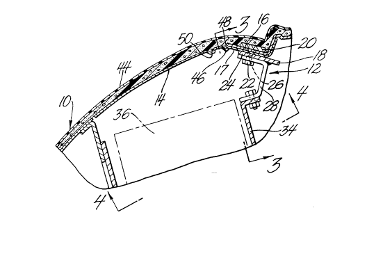
Referring now to the drawing, Figure
illustrates an interior of an automobile that includes
an instrument panel 10 that is equipped with an air bag
arrangement of the invention which is indicated
generally at 12.
The air bag arrangement 12 comprises a door 14
that is attached to a substrate 16 of the instrument
panel 10 to close an opening in the substrate 16 for
deployment of an air bag into the passenger compartment
of the automobile. The door 14 is customarily made of
aluminum or other light metal, but may be made of a
molded plastic material. The substrate 16 is generally
molded of a fiber reinforced structural plastic
material.
The door 14 has a hinged end 17 that is

attached to the substrate 16 by clamping the hinged end
beneath an edge portion of the substrate 16 that is next
to the air bag opening. The hinged end 17 is clamped to


:` 2 ~ 7 3 79 ~

P-678 - 5 -


the substrate by a frame 18 that is beneath the
substrate 16, a reinforcement bar 20 that is above the
edge portion of the substrate 16, that is on the covered
side of the substrate 16, and a plurality of fasteners
22, such as sheet metal screws that force the frame 18
and reinforcement bar 20 toward each other.
The frame 18 is generally rectangular as best
shown in figure 4. It includes a front bar 24 that has
a plurality of holes 26 for receiving the shanks of the
fasteners 22 that are attached to the reinforcement bar
20. The frame 18 further includes a front bracket 28
that is welded or otherwise suitably secured to the
front bar 20 and two side flanges 30. The bracket 28
and the two side flanges 30 each have two holes 32.
These six holes 32 are used to bolt or otherwise
suitably attach an air bag canister 34 beneath the air
bag opening of the substrate 16 as shown in figure 2.
The air bag canister 34 houses a deflated air
bag which is schematically shown at 36 and which
operates in a well known manner. Briefly, the air bag
is inflated by a gas generator (not shown) and deployed
in the passenger compartment through the air bag opening
when the automobile decelerates at a rate corresponding
to a front end collision.
Returning to figure 4, the frame 18 further
includes four side brackets 38. Two brackets are

attached to each side of the frame 18. These brackets

21737~

P-678 - 6 -


are used to attach the frame 18 to automotive body
structure such as a cross car beam, front of dash panel,
fire wall, or floor pan. The automobile structure is
schematically represented at 40 in figure 3. The frame
18 is attached to the automobile structure 40 by the
side brackets 38 and fasteners 42, such as nuts and bolt
shown in figure 3.
The instrument panel 12 includes a covering 44
that covers the substrate 16 and the door 14 so that the
covering of the door is an integral part of the covering
of the instrument panel 12. The covering 44 comprises
an outer skin and an underlying layer of foam, that are
customarily made of compatible thermoplastic materials,
such as polyvinylchloride and polyvinychloride foam or
polyurethane and polyurethane foam. The outer skin is
preferably weakened to provide tear lines for separating
the portion that covers the door 14 in a predictable
manner when the air bag is deployed. These tear lines
can be internal and invisible or external style lines.
The door 14 is attached to the substrate 16
before the door 14 and substrate 16 are covered by the
outer covering 44. The canister 34 may be attached to
the frame 18 either before or after the instrument panel
is covered. In fact the canister 34 may be attached to
the frame 18 after the instrument panel 10 is installed
in the automobile.

:: ~1737~

P-678 - 7 -


In any event, the installed instrument panel
10 and canister 34 work in a well known manner. When
the air bag 36 is deployed, the air bag 36 engages the
metal door 14 and pivots the metal door 14 outwardly
about the edge of the substrate 16. The metal door 14
preferably includes a crease 46 that underlies an
inturned lip 48 of the substrate 16. The crease 46
defines a primary hinge line of the door 14 which then
pivots about the inturned lip 48 to open. The metal
door 14 also preferably includes a second crease 50 that
is spaced from the primary hinge crease 46 toward the
free end of the door 14. This second crease provides a
secondary hinge line which allows the door 14 to flex
without bending at the hinge point during the initial
deployment of the air bag.
As the door 14 is pivoted outwardly by the
inflating air bag, the covering 44 is ruptured at the
front or free edge of the door 14 and then along the
sides of the door 14 forming a flap in the covering 44
that is opened along with the door 14 under the action
of the inflating air bag 36. The reaction force
imparted to the canister 34 by the inflating air bag 36
is transferred to the automotive body structure 40 by
the frame 18 and brackets 38. This isolates the
substrate 16 from the reaction force of the canister 34
produced by the inflation of air bag 34.


173~

P-678 - 8 -


This isolation and the reinforced attachment
each permit use of a thinner substrate while assuring
that the door 14 remains attached to the substrate when
the air bag 34 is deployed. On the other hand the
isolation in combination with the reinforced attachment
provides the best advantage.
The invention has been illustrated in
conjunction with an integral air bag door arrangement.
However, the invention can also be used in conjunction
with a separate door arrangement in which the covering
for the door is separate from the covering for the trim
product and applied to the door before it is attached to
the trim product. In other words, the invention has
been described in an illustrative manner, many
modifications and variations of the present invention in
light of the above teachings may be made. It is,
therefore, to be understood that, within the scope of
the appended claims, the invention may be practiced
otherwise than as specifically described.


Representative Drawing
A single figure which represents the drawing illustrating the invention.
Administrative Status

For a clearer understanding of the status of the application/patent presented on this page, the site Disclaimer , as well as the definitions for Patent , Administrative Status , Maintenance Fee  and Payment History  should be consulted.

Administrative Status

Title Date
Forecasted Issue Date Unavailable
(22) Filed 1996-04-10
(41) Open to Public Inspection 1996-10-25
Examination Requested 2003-03-17
Dead Application 2006-04-10

Abandonment History

Abandonment Date Reason Reinstatement Date
2004-04-13 FAILURE TO PAY APPLICATION MAINTENANCE FEE 2004-04-26
2005-04-11 FAILURE TO PAY APPLICATION MAINTENANCE FEE
2005-09-09 R30(2) - Failure to Respond

Payment History

Fee Type Anniversary Year Due Date Amount Paid Paid Date
Application Fee $0.00 1996-04-10
Registration of a document - section 124 $0.00 1996-07-04
Maintenance Fee - Application - New Act 2 1998-04-14 $100.00 1998-03-20
Maintenance Fee - Application - New Act 3 1999-04-12 $100.00 1999-04-08
Maintenance Fee - Application - New Act 4 2000-04-10 $100.00 2000-03-24
Maintenance Fee - Application - New Act 5 2001-04-10 $150.00 2001-03-23
Maintenance Fee - Application - New Act 6 2002-04-10 $150.00 2002-04-03
Request for Examination $400.00 2003-03-17
Maintenance Fee - Application - New Act 7 2003-04-10 $150.00 2003-03-21
Reinstatement: Failure to Pay Application Maintenance Fees $200.00 2004-04-26
Maintenance Fee - Application - New Act 8 2004-04-13 $200.00 2004-04-26
Owners on Record

Note: Records showing the ownership history in alphabetical order.

Current Owners on Record
DAVIDSON TEXTRON INC.
Past Owners on Record
BATCHELDER, BRUCE
BOOTH, ROBERT
GRAY, JOHN
ROGERS, JIM
Past Owners that do not appear in the "Owners on Record" listing will appear in other documentation within the application.
Documents

To view selected files, please enter reCAPTCHA code :


To view images, click a link in the Document Description column. To download the documents, select one or more checkboxes in the first column and then click the "Download Selected in PDF format (Zip Archive)" or the "Download Selected as Single PDF" button.

List of published and non-published patent-specific documents on the CPD .

If you have any difficulty accessing content, you can call the Client Service Centre at 1-866-997-1936 or send them an e-mail at CIPO Client Service Centre.


Document
Description 
Date
(yyyy-mm-dd) 
Number of pages   Size of Image (KB) 
Claims 1996-04-10 4 122
Description 1996-04-10 8 260
Cover Page 1996-04-10 1 16
Drawings 1996-04-10 2 65
Abstract 1996-04-10 1 22
Assignment 1996-04-10 8 347
Prosecution-Amendment 2003-03-17 1 54
Fees 2004-04-26 1 36
Prosecution-Amendment 2005-03-09 2 35